EP2595876B1 - Panneau de revêtement supportant la charge principale et élément de structure comportant au moins un panneau de revêtement supportant la charge principale - Google Patents
Panneau de revêtement supportant la charge principale et élément de structure comportant au moins un panneau de revêtement supportant la charge principale Download PDFInfo
- Publication number
- EP2595876B1 EP2595876B1 EP11741106.6A EP11741106A EP2595876B1 EP 2595876 B1 EP2595876 B1 EP 2595876B1 EP 11741106 A EP11741106 A EP 11741106A EP 2595876 B1 EP2595876 B1 EP 2595876B1
- Authority
- EP
- European Patent Office
- Prior art keywords
- reinforcing
- core layer
- reinforcement
- shell
- region
- Prior art date
- Legal status (The legal status is an assumption and is not a legal conclusion. Google has not performed a legal analysis and makes no representation as to the accuracy of the status listed.)
- Active
Links
Images




Classifications
-
- B—PERFORMING OPERATIONS; TRANSPORTING
- B64—AIRCRAFT; AVIATION; COSMONAUTICS
- B64C—AEROPLANES; HELICOPTERS
- B64C1/00—Fuselages; Constructional features common to fuselages, wings, stabilising surfaces or the like
- B64C1/06—Frames; Stringers; Longerons ; Fuselage sections
- B64C1/12—Construction or attachment of skin panels
-
- B—PERFORMING OPERATIONS; TRANSPORTING
- B29—WORKING OF PLASTICS; WORKING OF SUBSTANCES IN A PLASTIC STATE IN GENERAL
- B29D—PRODUCING PARTICULAR ARTICLES FROM PLASTICS OR FROM SUBSTANCES IN A PLASTIC STATE
- B29D99/00—Subject matter not provided for in other groups of this subclass
- B29D99/001—Producing wall or panel-like structures, e.g. for hulls, fuselages, or buildings
- B29D99/0021—Producing wall or panel-like structures, e.g. for hulls, fuselages, or buildings provided with plain or filled structures, e.g. cores, placed between two or more plates or sheets, e.g. in a matrix
-
- B—PERFORMING OPERATIONS; TRANSPORTING
- B32—LAYERED PRODUCTS
- B32B—LAYERED PRODUCTS, i.e. PRODUCTS BUILT-UP OF STRATA OF FLAT OR NON-FLAT, e.g. CELLULAR OR HONEYCOMB, FORM
- B32B3/00—Layered products comprising a layer with external or internal discontinuities or unevennesses, or a layer of non-planar shape; Layered products comprising a layer having particular features of form
- B32B3/02—Layered products comprising a layer with external or internal discontinuities or unevennesses, or a layer of non-planar shape; Layered products comprising a layer having particular features of form characterised by features of form at particular places, e.g. in edge regions
- B32B3/08—Layered products comprising a layer with external or internal discontinuities or unevennesses, or a layer of non-planar shape; Layered products comprising a layer having particular features of form characterised by features of form at particular places, e.g. in edge regions characterised by added members at particular parts
-
- B—PERFORMING OPERATIONS; TRANSPORTING
- B32—LAYERED PRODUCTS
- B32B—LAYERED PRODUCTS, i.e. PRODUCTS BUILT-UP OF STRATA OF FLAT OR NON-FLAT, e.g. CELLULAR OR HONEYCOMB, FORM
- B32B3/00—Layered products comprising a layer with external or internal discontinuities or unevennesses, or a layer of non-planar shape; Layered products comprising a layer having particular features of form
- B32B3/26—Layered products comprising a layer with external or internal discontinuities or unevennesses, or a layer of non-planar shape; Layered products comprising a layer having particular features of form characterised by a particular shape of the outline of the cross-section of a continuous layer; characterised by a layer with cavities or internal voids ; characterised by an apertured layer
- B32B3/28—Layered products comprising a layer with external or internal discontinuities or unevennesses, or a layer of non-planar shape; Layered products comprising a layer having particular features of form characterised by a particular shape of the outline of the cross-section of a continuous layer; characterised by a layer with cavities or internal voids ; characterised by an apertured layer characterised by a layer comprising a deformed thin sheet, i.e. the layer having its entire thickness deformed out of the plane, e.g. corrugated, crumpled
-
- B—PERFORMING OPERATIONS; TRANSPORTING
- B32—LAYERED PRODUCTS
- B32B—LAYERED PRODUCTS, i.e. PRODUCTS BUILT-UP OF STRATA OF FLAT OR NON-FLAT, e.g. CELLULAR OR HONEYCOMB, FORM
- B32B3/00—Layered products comprising a layer with external or internal discontinuities or unevennesses, or a layer of non-planar shape; Layered products comprising a layer having particular features of form
- B32B3/26—Layered products comprising a layer with external or internal discontinuities or unevennesses, or a layer of non-planar shape; Layered products comprising a layer having particular features of form characterised by a particular shape of the outline of the cross-section of a continuous layer; characterised by a layer with cavities or internal voids ; characterised by an apertured layer
- B32B3/30—Layered products comprising a layer with external or internal discontinuities or unevennesses, or a layer of non-planar shape; Layered products comprising a layer having particular features of form characterised by a particular shape of the outline of the cross-section of a continuous layer; characterised by a layer with cavities or internal voids ; characterised by an apertured layer characterised by a layer formed with recesses or projections, e.g. hollows, grooves, protuberances, ribs
-
- B—PERFORMING OPERATIONS; TRANSPORTING
- B32—LAYERED PRODUCTS
- B32B—LAYERED PRODUCTS, i.e. PRODUCTS BUILT-UP OF STRATA OF FLAT OR NON-FLAT, e.g. CELLULAR OR HONEYCOMB, FORM
- B32B5/00—Layered products characterised by the non- homogeneity or physical structure, i.e. comprising a fibrous, filamentary, particulate or foam layer; Layered products characterised by having a layer differing constitutionally or physically in different parts
- B32B5/18—Layered products characterised by the non- homogeneity or physical structure, i.e. comprising a fibrous, filamentary, particulate or foam layer; Layered products characterised by having a layer differing constitutionally or physically in different parts characterised by features of a layer of foamed material
-
- B—PERFORMING OPERATIONS; TRANSPORTING
- B32—LAYERED PRODUCTS
- B32B—LAYERED PRODUCTS, i.e. PRODUCTS BUILT-UP OF STRATA OF FLAT OR NON-FLAT, e.g. CELLULAR OR HONEYCOMB, FORM
- B32B7/00—Layered products characterised by the relation between layers; Layered products characterised by the relative orientation of features between layers, or by the relative values of a measurable parameter between layers, i.e. products comprising layers having different physical, chemical or physicochemical properties; Layered products characterised by the interconnection of layers
- B32B7/04—Interconnection of layers
-
- B—PERFORMING OPERATIONS; TRANSPORTING
- B64—AIRCRAFT; AVIATION; COSMONAUTICS
- B64C—AEROPLANES; HELICOPTERS
- B64C3/00—Wings
- B64C3/20—Integral or sandwich constructions
-
- B—PERFORMING OPERATIONS; TRANSPORTING
- B64—AIRCRAFT; AVIATION; COSMONAUTICS
- B64C—AEROPLANES; HELICOPTERS
- B64C3/00—Wings
- B64C3/26—Construction, shape, or attachment of separate skins, e.g. panels
-
- B—PERFORMING OPERATIONS; TRANSPORTING
- B64—AIRCRAFT; AVIATION; COSMONAUTICS
- B64D—EQUIPMENT FOR FITTING IN OR TO AIRCRAFT; FLIGHT SUITS; PARACHUTES; ARRANGEMENT OR MOUNTING OF POWER PLANTS OR PROPULSION TRANSMISSIONS IN AIRCRAFT
- B64D45/00—Aircraft indicators or protectors not otherwise provided for
-
- G—PHYSICS
- G01—MEASURING; TESTING
- G01N—INVESTIGATING OR ANALYSING MATERIALS BY DETERMINING THEIR CHEMICAL OR PHYSICAL PROPERTIES
- G01N19/00—Investigating materials by mechanical methods
- G01N19/08—Detecting presence of flaws or irregularities
-
- B—PERFORMING OPERATIONS; TRANSPORTING
- B32—LAYERED PRODUCTS
- B32B—LAYERED PRODUCTS, i.e. PRODUCTS BUILT-UP OF STRATA OF FLAT OR NON-FLAT, e.g. CELLULAR OR HONEYCOMB, FORM
- B32B2266/00—Composition of foam
- B32B2266/02—Organic
- B32B2266/0214—Materials belonging to B32B27/00
-
- B—PERFORMING OPERATIONS; TRANSPORTING
- B32—LAYERED PRODUCTS
- B32B—LAYERED PRODUCTS, i.e. PRODUCTS BUILT-UP OF STRATA OF FLAT OR NON-FLAT, e.g. CELLULAR OR HONEYCOMB, FORM
- B32B2266/00—Composition of foam
- B32B2266/04—Inorganic
-
- B—PERFORMING OPERATIONS; TRANSPORTING
- B32—LAYERED PRODUCTS
- B32B—LAYERED PRODUCTS, i.e. PRODUCTS BUILT-UP OF STRATA OF FLAT OR NON-FLAT, e.g. CELLULAR OR HONEYCOMB, FORM
- B32B2266/00—Composition of foam
- B32B2266/04—Inorganic
- B32B2266/045—Metal
-
- B—PERFORMING OPERATIONS; TRANSPORTING
- B32—LAYERED PRODUCTS
- B32B—LAYERED PRODUCTS, i.e. PRODUCTS BUILT-UP OF STRATA OF FLAT OR NON-FLAT, e.g. CELLULAR OR HONEYCOMB, FORM
- B32B2307/00—Properties of the layers or laminate
- B32B2307/10—Properties of the layers or laminate having particular acoustical properties
- B32B2307/102—Insulating
-
- B—PERFORMING OPERATIONS; TRANSPORTING
- B32—LAYERED PRODUCTS
- B32B—LAYERED PRODUCTS, i.e. PRODUCTS BUILT-UP OF STRATA OF FLAT OR NON-FLAT, e.g. CELLULAR OR HONEYCOMB, FORM
- B32B2307/00—Properties of the layers or laminate
- B32B2307/50—Properties of the layers or laminate having particular mechanical properties
- B32B2307/54—Yield strength; Tensile strength
-
- B—PERFORMING OPERATIONS; TRANSPORTING
- B32—LAYERED PRODUCTS
- B32B—LAYERED PRODUCTS, i.e. PRODUCTS BUILT-UP OF STRATA OF FLAT OR NON-FLAT, e.g. CELLULAR OR HONEYCOMB, FORM
- B32B2307/00—Properties of the layers or laminate
- B32B2307/50—Properties of the layers or laminate having particular mechanical properties
- B32B2307/582—Tearability
- B32B2307/5825—Tear resistant
-
- B—PERFORMING OPERATIONS; TRANSPORTING
- B32—LAYERED PRODUCTS
- B32B—LAYERED PRODUCTS, i.e. PRODUCTS BUILT-UP OF STRATA OF FLAT OR NON-FLAT, e.g. CELLULAR OR HONEYCOMB, FORM
- B32B2605/00—Vehicles
- B32B2605/18—Aircraft
-
- B—PERFORMING OPERATIONS; TRANSPORTING
- B32—LAYERED PRODUCTS
- B32B—LAYERED PRODUCTS, i.e. PRODUCTS BUILT-UP OF STRATA OF FLAT OR NON-FLAT, e.g. CELLULAR OR HONEYCOMB, FORM
- B32B2607/00—Walls, panels
-
- B—PERFORMING OPERATIONS; TRANSPORTING
- B32—LAYERED PRODUCTS
- B32B—LAYERED PRODUCTS, i.e. PRODUCTS BUILT-UP OF STRATA OF FLAT OR NON-FLAT, e.g. CELLULAR OR HONEYCOMB, FORM
- B32B3/00—Layered products comprising a layer with external or internal discontinuities or unevennesses, or a layer of non-planar shape; Layered products comprising a layer having particular features of form
- B32B3/02—Layered products comprising a layer with external or internal discontinuities or unevennesses, or a layer of non-planar shape; Layered products comprising a layer having particular features of form characterised by features of form at particular places, e.g. in edge regions
-
- B—PERFORMING OPERATIONS; TRANSPORTING
- B32—LAYERED PRODUCTS
- B32B—LAYERED PRODUCTS, i.e. PRODUCTS BUILT-UP OF STRATA OF FLAT OR NON-FLAT, e.g. CELLULAR OR HONEYCOMB, FORM
- B32B3/00—Layered products comprising a layer with external or internal discontinuities or unevennesses, or a layer of non-planar shape; Layered products comprising a layer having particular features of form
- B32B3/02—Layered products comprising a layer with external or internal discontinuities or unevennesses, or a layer of non-planar shape; Layered products comprising a layer having particular features of form characterised by features of form at particular places, e.g. in edge regions
- B32B3/06—Layered products comprising a layer with external or internal discontinuities or unevennesses, or a layer of non-planar shape; Layered products comprising a layer having particular features of form characterised by features of form at particular places, e.g. in edge regions for securing layers together; for attaching the product to another member, e.g. to a support, or to another product, e.g. groove/tongue, interlocking
-
- B—PERFORMING OPERATIONS; TRANSPORTING
- B64—AIRCRAFT; AVIATION; COSMONAUTICS
- B64D—EQUIPMENT FOR FITTING IN OR TO AIRCRAFT; FLIGHT SUITS; PARACHUTES; ARRANGEMENT OR MOUNTING OF POWER PLANTS OR PROPULSION TRANSMISSIONS IN AIRCRAFT
- B64D45/00—Aircraft indicators or protectors not otherwise provided for
- B64D2045/0085—Devices for aircraft health monitoring, e.g. monitoring flutter or vibration
-
- Y—GENERAL TAGGING OF NEW TECHNOLOGICAL DEVELOPMENTS; GENERAL TAGGING OF CROSS-SECTIONAL TECHNOLOGIES SPANNING OVER SEVERAL SECTIONS OF THE IPC; TECHNICAL SUBJECTS COVERED BY FORMER USPC CROSS-REFERENCE ART COLLECTIONS [XRACs] AND DIGESTS
- Y10—TECHNICAL SUBJECTS COVERED BY FORMER USPC
- Y10T—TECHNICAL SUBJECTS COVERED BY FORMER US CLASSIFICATION
- Y10T428/00—Stock material or miscellaneous articles
- Y10T428/23—Sheet including cover or casing
- Y10T428/239—Complete cover or casing
-
- Y—GENERAL TAGGING OF NEW TECHNOLOGICAL DEVELOPMENTS; GENERAL TAGGING OF CROSS-SECTIONAL TECHNOLOGIES SPANNING OVER SEVERAL SECTIONS OF THE IPC; TECHNICAL SUBJECTS COVERED BY FORMER USPC CROSS-REFERENCE ART COLLECTIONS [XRACs] AND DIGESTS
- Y10—TECHNICAL SUBJECTS COVERED BY FORMER USPC
- Y10T—TECHNICAL SUBJECTS COVERED BY FORMER US CLASSIFICATION
- Y10T428/00—Stock material or miscellaneous articles
- Y10T428/24—Structurally defined web or sheet [e.g., overall dimension, etc.]
-
- Y—GENERAL TAGGING OF NEW TECHNOLOGICAL DEVELOPMENTS; GENERAL TAGGING OF CROSS-SECTIONAL TECHNOLOGIES SPANNING OVER SEVERAL SECTIONS OF THE IPC; TECHNICAL SUBJECTS COVERED BY FORMER USPC CROSS-REFERENCE ART COLLECTIONS [XRACs] AND DIGESTS
- Y10—TECHNICAL SUBJECTS COVERED BY FORMER USPC
- Y10T—TECHNICAL SUBJECTS COVERED BY FORMER US CLASSIFICATION
- Y10T428/00—Stock material or miscellaneous articles
- Y10T428/24—Structurally defined web or sheet [e.g., overall dimension, etc.]
- Y10T428/24273—Structurally defined web or sheet [e.g., overall dimension, etc.] including aperture
- Y10T428/24322—Composite web or sheet
-
- Y—GENERAL TAGGING OF NEW TECHNOLOGICAL DEVELOPMENTS; GENERAL TAGGING OF CROSS-SECTIONAL TECHNOLOGIES SPANNING OVER SEVERAL SECTIONS OF THE IPC; TECHNICAL SUBJECTS COVERED BY FORMER USPC CROSS-REFERENCE ART COLLECTIONS [XRACs] AND DIGESTS
- Y10—TECHNICAL SUBJECTS COVERED BY FORMER USPC
- Y10T—TECHNICAL SUBJECTS COVERED BY FORMER US CLASSIFICATION
- Y10T428/00—Stock material or miscellaneous articles
- Y10T428/249921—Web or sheet containing structurally defined element or component
- Y10T428/249923—Including interlaminar mechanical fastener
Definitions
- the invention relates to a main load-bearing planking shell and a structural component having at least one main load-carrying planking shell and a support structure for fastening the main load-bearing planking shell.
- the object of the invention is to provide a main load-carrying planking shell, which can be formed in an improved manner damage tolerant and used as a damage tolerant component of a structural component.
- the object of the invention is furthermore to provide a structural component with at least one main load-carrying planking shell and a support structure for fastening the main load-bearing planking shell, which is designed to be damage tolerant.
- planking according to the invention in particular a limitation of any occurring or existing or resulting damage in the Planking according to the invention achieved.
- Various embodiments of the planking according to the invention are designed such that any damage occurring to the same are limited over a locally defined area.
- This can be achieved according to the invention by a core-layer reinforcing region according to the invention and preferably a plurality of core-layer reinforcing regions according to the invention, which are suitably arranged to define skin regions separate from reinforcing regions so that portions of the core layer respectively located between reinforcement areas.
- a plurality of reinforcing regions can be arranged circumferentially, so that these reinforcing regions each enclose a core layer section.
- reinforcing parts according to embodiments of the invention and in accordance with the invention are introduced into the planking shell. These reinforcing parts may be arranged such that they form a series or sequence of reinforcing parts, the course of which may be provided like an inventive course of the reinforcing regions.
- a main load-bearing cladding shell for a structural component of a flow body.
- the planking shell is formed as a sandwich and from an inner skin portion, an outer skin portion and a thrust load-receiving core layer located between them, which connects the inner and the outer skin portion flat.
- the planking shell can have a plurality of reinforcing parts and / or reinforcing devices for influencing shear stresses in the core layer.
- the reinforcing devices comprise reinforcing members which, in one aspect of the invention, each penetrate at least 85% of the thrust receiving core layer in the thickness direction thereof to improve the crack resistance of the cladding shell.
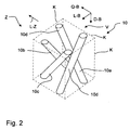
- the reinforcing devices are each formed from a combination of at least two reinforcing parts arranged in a contiguous volume part of the planking shell, wherein the reinforcing devices can be arranged one behind the other in a reference longitudinal direction of an intermediate area.
- the reinforcing members and / or reinforcing devices may be arranged in groups in each one of a plurality of parts by volume of the planking shell, wherein each group of a volume part is formed in each case from a combination of at least two reinforcing parts.
- the reinforcing parts of a reinforcing device can be arranged in each case in a contiguous fictitious volume part of the planking shell.
- the reinforcing parts may be provided in particular that they each have a maximum deviation of 30 degrees and in the preferred embodiment of 10 degrees the same orientation with respect to the thickness direction of the planking shell. Furthermore, the orientations of the reinforcing parts can be provided cyclically with respect to the further coordinate directions of the planking shell.
- the or a part of the reinforcing parts are arranged in the planking shell in groups of reinforcing devices respectively located in a volume part of the plating shell, the volume parts being along a reference longitudinal direction or the rib longitudinal direction are arranged one behind the other, wherein each group of a volume part is formed in each case from a combination of at least two reinforcing parts, the orientations of which each deviate a maximum of 30 degrees from the thickness direction of the planking shell and which in a regular or irregular manner around a central axis of the volume part are arranged.
- the volume part is a fictional volume part of the plating shell selected to illustrate the arrangement of reinforcement parts, which extends over the entire thickness of the plating shell and is shaped in particular as a cuboid.
- the center axis of the volume part may be the central axis or the axis of symmetry which runs in the thickness direction of the planking shell and connects the cross-sectional area center of gravity of the cuboid.
- Plant shell is generally understood herein to mean a shell part which according to the invention is designed as a sandwich shell and can be curved or not curved.
- the orientation of the reinforcing parts can be provided in particular within a range between 45 degrees and 10 degrees, these angle amounts being defined by the size of the angle between the longitudinal direction of the respective reinforcing part and the thickness direction of the planking shell at this point.
- At least a part of the reinforcing parts and / or reinforcing devices is arranged such that their ends at least partially project through the inner skin section and / or the outer skin section.
- the inner skin portion and / or the outer skin portion of the planking shell is formed in each case from a plurality of skin layers. It can be provided that at least some of the reinforcing parts and / or reinforcing devices protrude through some of the skin layers and in particular not all of the skin layers.
- the reinforcing devices are arranged one behind the other in a reference longitudinal direction.
- the arrangement of reinforcing devices may in particular be located in an elongate reinforcement region which extends with its longitudinal direction along a core layer end region or along a connection region provided for fastening a rib arrangement or a carrier part, wherein the width of the reinforcement region is at most ten times the thickness of the Can be plank in this area.
- a plurality of rows of reinforcing members may be disposed one behind the other in the reference longitudinal direction, the rows of reinforcing members being arranged so that their reinforcing members mesh with each other in the direction of the reference longitudinal extent of the cladding panel.
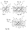
- a reinforcing device may each be formed from a pair of reinforcing parts, wherein the reinforcing members of each pair of reinforcing members are oriented toward each other so that the reinforcing members form a paired X-shaped reinforcing apparatus as viewed in a longitudinal direction of the panel shell.
- the reinforcing members may be at least partially pin-shaped and / or needle-shaped at least at one end.
- reinforcing members may be plate-shaped.
- at least one end of reinforcing parts can each be provided with a foot-like widening.
- the plate-shaped reinforcing parts and / or reinforcing devices of a reinforcing device can be arranged interlocking.
- the thrust-receiving core layer is formed of a plurality of juxtaposed in the longitudinal extent of the foam layer core layer sections, which are connected to each other on the adjacent sides by a core layer reinforcing region extending transversely to the longitudinal extent of the core layer therethrough the reinforcing region is formed of a material which has at least twice the rigidity of the shear-load-receiving core layer.
- the thrust load receiving core layer is formed of plate-shaped core layer sections, and the reinforcing section extends between the core layer sections for connection thereof.
- the core layer reinforcing region may in particular be formed from resin.
- a plurality of reinforcing parts at least partially project through the reinforcing area.
- reinforcing members are inserted with one end into the reinforcement region and extend with their remaining region in the shear-load-receiving core layer.
- amplification devices are integrated along an environmental region of a plurality of core layer reinforcement regions in the thrust-receiving core layer of the cover shell.
- the surrounding area for the arrangement of the amplification devices may be on extend both sides of the core layer reinforcement region up to a maximum of ten times and in a preferred embodiment at most twice the thickness of the plating shell at the respective location of the core layer reinforcement region.
- a plurality of rows of reinforcing members are arranged one behind the other in the longitudinal direction along an environmental region of at least one core layer reinforcing region, the rows of reinforcing members being arranged such that their reinforcing members extend in the direction of the longitudinal extent of the outer peripheral portion of the plating shell combed into one another.
- a structural component is provided with at least one main load-carrying or main-carrying planking shell and a support structure for fastening the planking shell.
- the planking shell is formed as a sandwich and from an inner skin portion, an outer skin portion and a thrust load-receiving core layer located between them; which connects the inner and the outer skin portion flat.
- the carrier structure is formed from at least two carrier components extending in each case along a longitudinal direction of the structural component and at least one rib arrangement extending between and transversely thereto and along its longitudinal direction with the cladding shell for the planar support of the cladding shell on the carrier structure.
- the rib arrangement has in this case: a rib projecting from the cladding shell in its transverse direction and an adjoining flange part which is connected in a planar manner to the cladding shell along the rib arrangement longitudinal direction.
- reinforcing profiles are arranged in the cladding shell along a cladding shell section running transversely to the rib arrangement longitudinal direction, which join the flange part and the outer skin section for stabilizing the cladding shell when they are damaged from the outside.
- the connection part for supporting the planking shell on the support structure in the thickness direction of the planking shell is located outside the plating shell and flat against the inner skin portion attached thereto is attached.
- the at least one profiled support is arranged within the connection region, as seen in plan view of the planar extension of the planking shell.
- reinforcing devices are integrated at two intermediate regions or reinforcing regions extending in the rib assembly longitudinal direction and along the lateral ends of the skin shell section. These are in particular designed with reinforcing parts projecting through the core layer, wherein the reinforcing parts and / or reinforcing devices are arranged at least in sections along the rib arrangement longitudinal direction, ie in the rib arrangement longitudinal direction one behind the other.
- connection part lies outside the plating shell and rests flat against the inner skin section
- inner and the outer skin section remain intact. This makes it possible to produce the planking shell with continuous inner and outer skin sections, which in turn makes it possible to produce the planking shell with a resin infusion or wet process (liquid composite molding).
- connection part for fixing the same with the planking be glued flat with the inner skin portion, so that the connection part is held due to the surface provided by the adhesive bond strength on the planking shell.
- connection part with the planking shell with the inner skin portion by means of connecting elements such as rivets (blind rivets, pegs, etc.) may be connected, in particular in at least two along mutually or parallel rows at regular intervals from each other.
- connection region provision can be made, in particular, for the inner skin section on which the connection part rests to have a greater material thickness than the inner skin section laterally of the connection region.
- this thickening in terms of its areal extent in a range which deviates by a maximum of 10 times the thickness of the planking of the edge profile of the connection region.
- This increase in thickness can be realized by arranging further layers in this region extending flatly on the surface of the inner skin section facing the core layer and / or on the outer surface of the planking shell.
- the reinforcing parts are arranged in the core layer such that their ends at least partially project through the inner skin section and / or the outer skin section, wherein in particular the inner skin section and the outer skin section respectively is formed of several layers and penetrate at least a portion of the reinforcing members at least a first layer.
- a structural component is provided with at least one main load-carrying planking shell and a support structure for fastening the planking shell, wherein the planking shell is formed as a sandwich and from an inner skin portion, an outer skin portion and a shear load-receiving core layer located between them which flatly interconnects the inner and outer skin portions, the support structure being formed of at least one plate-shaped attachment part extending transversely thereto and along a reference longitudinal direction to support the plating shell on the support structure outside the support structure located and flat on the inner skin portion adjacent to this is attached.
- a plurality of reinforcing parts is integrated in the connection region of the plate-shaped connecting part along the reference longitudinal direction.
- at least some of the reinforcing parts are arranged in the core layer such that their ends at least partially project through the inner skin portion and / or the outer skin portion.
- connection part lies outside the plating shell and rests flat against the inner skin section
- inner and the outer skin section remain intact. This makes it possible to produce the planking shell with continuous inner and outer skin sections, which in turn makes it possible to produce the planking shell with a resin infusion or wet process (liquid composite molding).
- connection part for fixing the same with the planking shell can be glued flat with the inner skin portion.
- connection part may be connected to the planking shell with the inner skin portion by means of connecting elements such as rivets, in particular in at least two along mutually or mutually parallel rows at regular intervals from each other.
- connection region provision can be made, in particular, for the inner skin section on which the connection part rests to have a greater material thickness than the inner skin section laterally of the connection region.
- this thickening with regard to its areal extent may be in a region which deviates from the edge profile of the connection region by at most 10 times the thickness of the cladding shell. This increase in thickness can be realized by arranging further layers in this region extending flatly on the surface of the inner skin section facing the core layer and / or on the outer surface of the planking shell.
- the inner skin portion and the outer skin portion is formed in each case of a plurality of layers, wherein the reinforcing members penetrate at least a first layer of the inner skin portion and the outer skin portion.
- At least one profile carrier running along the reference longitudinal direction is arranged in the cladding shell to form a reinforcement section in the connection region of the plate-shaped connection part, which contributes to the stabilization of the cladding shell with the inner skin section and the outer skin section Damage of the same is connected and thereby mutually supported from the outside.
- the parts or parts of the reinforcing parts in the planking shell are arranged in reinforcing devices in groups of reinforcing parts situated respectively in a volume part of the planking shell, the volume parts being along a reference
- Each group of a volume part is formed in each case of a combination of at least two reinforcing parts, the orientations of each differ by a maximum of 30 degrees from the thickness direction of the planking shell and the regular or irregular manner about a central axis of the Volume parts are arranged around.
- the volume part is a fictional volume part of the plating shell selected to illustrate the arrangement of reinforcement parts, which extends over the entire thickness of the plating shell and is shaped in particular as a cuboid.
- the center axis of the volume part may be the central axis or the axis of symmetry which runs in the thickness direction of the planking shell and connects the cross-sectional area center of gravity of the cuboid.
- the planking shell for influencing shear stresses in the core layer may comprise a plurality of reinforcement parts and / or reinforcement devices arranged in the intermediate regions, each of which is formed from a combination of at least two reinforcement parts arranged in a continuous volume part of the planking shell.
- the reinforcing parts and / or reinforcing devices are arranged one behind the other in the longitudinal direction of the intermediate region.
- the orientation of the reinforcing parts is provided within a range between 45 degrees and 10 degrees, these angle amounts being defined by the size of the angle between the longitudinal direction of the respective reinforcing part and the thickness direction of the planking at this point.
- the reinforcing devices may be arranged one behind the other in the rib assembly longitudinal direction and each formed of a pair of reinforcing members, the reinforcing members of each pair of reinforcing members being oriented to each other such that the reinforcing members are X-shaped as viewed in a longitudinal direction of the skin panel Form reinforcement device.
- the reinforcing members may be at least partially pin-shaped.
- reinforcing devices at least partially plate-shaped and in each case in the rib assembly longitudinal direction extending reinforcing members are used.
- the thrust-receiving core layer may include a core-layer reinforcement region extending in at least one of the two intermediate or side regions and in the rib assembly longitudinal direction and extending therethrough transversely to the longitudinal extent of the thrust-receiving core layer, wherein the reinforcement region is formed of a material having a thickness of has at least twice the rigidity of the thrust-receiving core layer.
- the core layer reinforcing region may in particular be made of resin and z. B. be formed of epoxy resin.
- the structural member may be configured such that a plurality of the reinforcing members project through the core layer reinforcing portion, respectively.
- a flow body is provided with a structural component, wherein the structural component is designed as a main load-bearing structural part and according to one of the aforementioned embodiments.
- a bulk load bearing skin for a structural member of a body of flow, said skin being sandwiched and formed of an inner skin portion, an outer skin portion and a thrust load-receiving core layer therebetween, said inner and outer skin portions the shovel-receiving core layer is formed from a plurality of juxtaposed in the longitudinal extent of the foam layer core layer sections, which are connected to each other on the adjacent sides by a core layer reinforcement region, which is transverse to the longitudinal extent of the core layer through this extends through.
- the core layer reinforcing region may be formed of resin.
- the surrounding area for the arrangement of the reinforcing devices may extend on both sides of the core layer reinforcing area to a maximum of twice the thickness of the plating shell at the respective location of the core layer reinforcing area.
- the reinforcing devices are arranged one behind the other in the longitudinal direction of the core layer reinforcing region and each formed from a combination of at least two arranged in a contiguous volume part of the Plankungsschale reinforcing parts, wherein in the combination of the reinforcing members, each with a Deviation of maximum 10 degrees have the same orientation with respect to the thickness direction of the plank and wherein the orientations of the reinforcing parts with respect to the other coordinate directions the planking shell are provided cyclically.
- the orientation of the reinforcing members may be provided within a range between 45 degrees and 10 degrees, these angular amounts being defined by the size of the angle between the longitudinal direction of the respective reinforcing member and the thickness direction of the skin panel at that location.
- the reinforcing members and / or reinforcing devices may be arranged one behind the other in particular in the longitudinal direction of the core layer reinforcing portion and each formed of a pair of reinforcing members, the reinforcing members of each pair of reinforcing members being oriented toward each other such that the reinforcing members are mutually one in a longitudinal extension of the shell panel seen form X-shaped reinforcing device.
- the reinforcing members and / or reinforcing devices may be at least partially pin-shaped. It can also be provided that several of the reinforcing parts project through the reinforcing area in each case.
- the structure component of a flow body provided with at least one main load-carrying cladding shell and the support structure for fastening the cladding shell and the formation of the cladding shell of core layer sections, which are connected to each other at the adjacent sides by a core layer reinforcing region according to the aforementioned aspect of the invention may be provided in particular in combination with the use of a rib arrangement in which reinforcement profiles are arranged along a cladding shell section running transversely to the rib arrangement longitudinal direction.
- the arrangement and design of the reinforcing profiles can be designed according to one of the aforementioned embodiments.
- a flow body may further be provided with a structural component, wherein the structural component is designed as a main structural component and according to one of the aforementioned embodiments.
- a structural component of a flow body with at least one such main load-bearing cladding shell described above and a support structure for fastening the cladding shell is also provided.
- the support structure is formed from at least two each along a longitudinal direction of the structural component extending support members and at least one extending transversely to these and along its longitudinal direction with the plank shell rib arrangement for planar support of the planking on the support structure and in particular may have the features mentioned herein in this context.
- a flow body may be provided with a structural component, which is designed as a main load-bearing structural component and is formed according to one or more of the aforementioned features.
- a main load-bearing cladding shell for a structural component which is formed in its area extending inner area as a sandwich component and an inner skin portion, an outer skin portion and a schublast-receiving core layer located between them, the the inner and outer skin sections are joined together in a planar manner, the cladding shell being adapted for attachment to a support member having an outer edge portion with an outer edge and comprising: a non-crimp connection area along the edge having the inner skin portion, the outer skin portion and a monolithic interlayer.
- reinforcing devices are integrated, which protrude through the thrust load-receiving core layer.
- an intermediate region is provided in front of the core layer-free connection region in which the thickness of the thrust load-receiving core layer continuously reduces towards the edge thereof to form a wedge-shaped section of the monolithic intermediate layer at least between the latter outer skin portion facing side of the thrust load-receiving core layer and the outer Skin portion or between the inner skin portion facing side of the thrust-receiving core layer and the inner skin portion.
- reinforcing parts of the reinforcing parts and / or reinforcing devices can partially protrude through the two wedge-shaped sections of the monolithic intermediate layer.
- the core layer end region for the arrangement of the reinforcement parts and / or reinforcement devices may extend from the edge of the core layer end to a maximum of four times the thickness of the cover shell at the edge of the core layer end.
- the reinforcing devices are arranged one behind the other in the structural component longitudinal direction, each of which is formed from a combination of at least two reinforcing parts arranged in a continuous volume part of the planking shell, wherein the reinforcing parts and / or reinforcing devices seen in the longitudinal direction of the intermediate region or the region to be reinforced are arranged one behind the other, wherein in the combination of the reinforcing members each with a deviation of at most 10 degrees have the same orientation with respect to the thickness direction of the planking shell and wherein the orientations of the reinforcing members with respect to further coordinate directions of the plank shell are provided cyclically.
- the orientation of the reinforcing parts is generally provided within an angular range between 70 degrees and 0 degrees, these angle amounts being defined by the size of the angle between the longitudinal direction of the respective reinforcing part and the thickness direction of the planking shell at this point.
- the longitudinal orientations of the reinforcing members are located in an angular range between 45 degrees and 10 degrees.
- the further coordinate directions are the two coordinate directions running in the plane longitudinal extent of the planking shell, ie the plating shell longitudinal direction and the plating shell transverse direction.
- at least one further reinforcement part may additionally be arranged in the volume part, which is aligned parallel to a further reinforcement part in the volume part.
- reinforcing parts can generally also be arranged in the volume element.
- the reinforcing members and / or reinforcing devices may be arranged one behind the other in particular in the rib assembly longitudinal direction and each formed of a pair of reinforcing members, the reinforcing members of each pair of reinforcing members being oriented to each other such that the reinforcing members are mutually one in a longitudinal extension of the panel shell seen form X-shaped reinforcing device.
- the reinforcing parts may in particular be designed at least partially pin-shaped.
- a different number and shape of pin-shaped arranged in the respective contiguous volume parts of the plank shell reinforcing parts may be provided, for. B. in a first volume part two reinforcing parts, in the subsequent second volume part four reinforcing parts and in the subsequent third volume part three reinforcing parts.
- the volume parts are fictitious areas whose boundaries are defined in such a way that the respective arrangement of reinforcement parts is arranged or contained therein.
- the volume parts can be defined in particular cuboid or cube-shaped. Different parts by volume of a sequence of volume parts arranged one behind the other in the respective longitudinal direction can have different sizes of parts by volume.
- the volume parts can also overlap in the longitudinal direction if a reinforcement part of one volume part engages in the interior of a respectively adjacent other volume part.
- the alignment of the volume parts is in particular provided such that a central axis or axis of symmetry of the volume parts has the same orientation as the orientation of the respectively relevant for the arrangement of the reinforcement parts longitudinal axis of the planking shell. That is, in a straight-line relevant for the arrangement of the reinforcing parts longitudinal direction, the volume parts are in particular with the same orientation arranged, ie, these have mutually parallel central axis or axis of symmetry, when the respective relevant longitudinal axis of the planking shell is rectilinear.
- the thrust-receiving core layer may also have a reinforcement region (which extends in at least one of the two side regions and in the structural component longitudinal direction and extends therethrough transversely to the longitudinal extent of the shear-loading-absorbent core layer;
- the reinforcing region may in particular be formed of resin, It may also be provided that a plurality of reinforcing parts project through the reinforcing region in each case.
- a transition region may be provided in the outer edge portion of the planking shell, in which the thickness of the monolithic intermediate layer is reduced towards the outer edge to reduce the cross-sectional thickness of the planking shell.
- reinforcing devices may be arranged according to the invention.
- a structural component of a flow body with at least one such main load-bearing cladding shell described above and a support structure for fastening the cladding shell in such a structural component can be provided that the support structure of at least two each along a longitudinal direction of the structural component extending support members and at least one extending transversely to these and along its longitudinal direction with the plank shell rib arrangement for planar support of the planking on the support structure is formed and in particular may have the features mentioned herein in this context.
- a main load-bearing cladding shell for a structural component may be provided, which in its area extending inner area as a sandwich component and an inner skin portion, a outer skin portion and a shear load-receiving core layer located between them is formed, which connects the inner and the outer skin portion with each other, wherein the planking panel is adapted for attachment to a support member having an outer edge portion with an outer edge and comprising: a along rim-free terminal portion having the inner skin portion, the outer skin portion, and a monolithic interlayer, wherein in a core layer end portion along the outer edge portion of the plating shell are integrated reinforcing devices according to the invention which protrude through the thrust-receiving core layer.
- the term "flow body” is understood to mean a body which is flowed around by a flow and thus has a flow surface, which in particular forms a section of the outside flow around a vehicle.
- the flow body may in particular be a body surrounded by air and thus an aerodynamic body.
- An aerodynamic body in this context may generally be part of a vehicle and in particular part of an aircraft.
- the vehicle may also be a ground-based vehicle and the aerodynamic body may be a spoiler.
- the flow may be a liquid flow and the flow body may be a hull or a part thereof.
- the plank according to the invention is a portion of the planking of an aircraft part or aircraft part and z.
- rudder of a tail and in particular a horizontal stabilizer or a vertical stabilizer and a tailplane fin or fin or a tailplane rudder or a rudder rudder, a wing, a control valve or a high-lift flap, a canard or a fuselage, ie generally an aerodynamic body, in particular its box girder or box girder area (also called "box structure").
- the box girder area of an airframe part can, in particular, be the middle part of the airframe part which, viewed in the assumed flow direction, lies between a front edge area or nose region and a trailing edge region of the airframe part.
- the load-bearing structural components of the box girder area are formed by longitudinal girders running in the spanwise direction and ribs extending therebetween and attached to them, in particular according to the prior art.
- the planking according to the invention may be attached to one side or both opposite sides of the load-bearing structural components, so that their outer sides each form a flow surface.
- the predetermined maximum force of the Planking shell according to the invention is the force or results, for example, from the force due to a striking of a height of 20 meters on the plank shell dropped tool (manufacturing damage), the force or arises, for example, due to the force the impact of a traveling maintenance vehicle (maintenance damage) on the plating shell or a structural part with such a plating shell or is the force or results, for example, from the force due to the impact of a body with a maximum weight at an assumed speed of the aircraft and thus flow velocity (" operating loss ").
- planking case damage is allowed, which still ensures the airworthiness ( airworthiness ) of the aircraft.
- a structural component of a flow body with a cladding shell and a cladding shell of a flow body wherein the cladding shell is integrated in the structural component such that it forms a flow surface and at the same time is a main load-bearing component of the flow body.
- a structural component or a cladding shell of a structural component of the flow body is formed as a main load-bearing structural part.
- the term "main load-bearing” or “main load-bearing” is understood to mean a structural component or component thereof or a cladding shell which absorbs and transmits main loads as regards its load due to external forces in the flow body.
- the main load bearing components of the flow body are to be interpreted such that These must be maintained as a constituent part of the assumed maximum external forces and must be able to transmit minimum loads as before.
- Planking shell is a "damage tolerant" component or a “damage tolerant” component, as in the occurrence of a predetermined external maximum force damage to the planking is accepted, but the damage must not occur in such a way, the so-called maximum allowable damage ( al / owable damage limit ), wherein the maximum allowable damage of the flow body must be such that the planking shell as a whole can still fulfill its flow function. If the maximum allowable damage is exceeded, repair or replacement of the plating shell must take place immediately.
- the reinforcing members and / or reinforcing devices provided in the respective plating shell in the various aspects of the invention and / or embodiments and variants of the invention may generally be embodied according to the embodiments mentioned herein.
- the respective direction or longitudinal direction along which the reinforcing parts and / or reinforcing devices are arranged in the cladding shell in the respective application depends on the orientation and course of the region of the cladding shell to be reinforced in the respective application, also referred to as intermediate region or reinforcing region in this context. from.
- the direction of a region with which the absorption of shear stresses and thus the avoidance of cracks in the core layer can be achieved can be the respective longitudinal direction.
- the respective longitudinal direction or the course along which the reinforcing devices are arranged according to the invention it may be provided: in the connection or fastening of the plating shell with a rib arrangement, the rib arrangement longitudinal direction, in the formation of core layer sections of core layer reinforcing regions In the longitudinal direction or the longitudinal course of the reinforcing regions or a portion thereof, in the formation of the planking shell with an outer edge portion with a non-core connection area along the course of or along the longitudinal direction thereof or a section of the same.
- the inventively provided arrangement of reinforcing members and / or reinforcing devices is thus designed such that the reinforcing members and / or reinforcing devices along an elongated to be reinforced region or reinforcing region of the planking panel and in the longitudinal direction thereof are arranged one behind the other, with this measure, the forwarding of shear stresses to prevent in the planking field.
- the reinforcing region or the longitudinal direction of the same can be rectilinear or curvilinear.
- the planking shell for influencing shear stresses in the core layer has a plurality of reinforcement parts arranged in an intermediate region of the planking shell, which extends along the planar extension of the planking shell / or amplification devices.
- the reinforcing devices are each formed from a combination of at least two reinforcing parts arranged in a contiguous volume part of the planking shell, the reinforcing devices being arranged one after the other in the longitudinal direction of the intermediate area or region to be reinforced, and wherein in the combination of the reinforcing members, each with a deviation of at most 10 degrees have the same orientation with respect to the thickness direction of the planking shell and wherein the reinforcing members are arranged cyclically with respect to the other coordinate directions of the plank shell.
- the orientation of the reinforcing parts is generally provided within an angular range between 70 degrees and 0 degrees, these angular amounts being defined by the size of the angle between the longitudinal direction of the respective reinforcing part and the thickness direction of the planking at this point.
- the longitudinal orientations of the reinforcing parts are located in an angular range between 45 degrees and 10 degrees.
- the further coordinate directions are the two coordinate directions running in the planar longitudinal extension of the cladding shell, that is to say the cladding shell longitudinal direction and the cladding shell transverse direction.
- At least one further reinforcement part may additionally be arranged in the volume part, which is aligned parallel to a further reinforcement part in the volume part.
- further reinforcing parts can generally also be arranged in the volume element.
- a different number and shape of pin-shaped arranged in the respective contiguous volume parts of the plank shell reinforcing parts may be provided, for. B. in a first volume part two reinforcing parts, in the subsequent second volume part four reinforcing parts and in the subsequent third volume part three reinforcing parts.
- the volume parts are fictitious areas whose boundaries are defined in such a way that the respective arrangement of reinforcement parts is arranged or contained therein.
- the volume parts can be defined in particular cuboid or cube-shaped. Different parts by volume of a sequence of volume parts arranged one behind the other in the respective longitudinal direction can have different sizes of parts by volume.
- the volume parts can also overlap in the longitudinal direction if a reinforcement part of one volume part engages in the interior of a respectively adjacent other volume part.
- the alignment of the volume parts is in particular provided such that a central axis or axis of symmetry of the volume parts has the same orientation as the orientation of the respectively relevant for the arrangement of the reinforcement parts longitudinal axis of the planking shell. That in a straight line relevant to the arrangement of the reinforcing parts longitudinal direction, the volume parts are arranged in particular with the same orientation, i. these have mutually parallel central axis or axis of symmetry, when the respective relevant longitudinal axis of the planking shell is rectilinear.
- the term "thickness direction of the planking shell” is understood to mean the direction of the shortest distance line between the inner skin section and the outer skin section at the respective point of the planking shell.
- longitudinal extent of the cladding shell is understood to mean the local orientation of the center plane of the cladding shell, which can be curved or unrestricted locally or over the entire respectively considered section thereof.
- Orientation of the reinforcing parts is understood to mean the direction of the longitudinal axis of the reinforcing parts.
- the longitudinal axis of the reinforcing parts may be the axis of symmetry and in an asymmetrical and z.
- longitudinal axis of the planking shell relevant to the arrangement of the reinforcement devices is understood according to the invention to mean the longitudinal direction of the respective intermediate region.
- a pair of reinforcing members or exactly two reinforcing members are arranged in at least a volume part or in all volume parts along a respective relevant for the arrangement of the reinforcing members longitudinal axis of the plank are oriented to one another in such a way that they are each arranged X-shaped in the respective longitudinal axis of the planking shell relevant for the arrangement of the reinforcement parts.
- longitudinal extent of the cladding shell is understood to mean a direction or a planar extent which is located in the plane which is spanned by the transverse direction of the cladding shell and the longitudinal direction of the cladding shell at the respective location.
- the reinforcing parts may be designed in particular pin-shaped or rod-shaped.
- reinforcing members may be formed plate-shaped. It can be provided in particular that at least in each case two seen in the longitudinal direction of the intermediate region X-shaped plate-shaped reinforcing members are arranged interlocking. Furthermore, it can be provided in particular that the plate-shaped reinforcing parts extend in their width direction, in particular in the longitudinal direction of the intermediate region or in the respective longitudinal axis of the plating shell relevant to the arrangement of the reinforcing parts and / or reinforcing devices.
- the planking shell B or planking panel provided according to the invention is provided as a main-load-carrying covering part or planking part of a flow body and in particular of an aerodynamic body.
- the FIG. 1 a shows a schematic plan view of a structural component 1 or a section of a vertical stabilizer as an example of the flow body or aerodynamic body according to the invention with a main load-bearing cladding shell B, which can generally also be designed as a cladding panel.
- the illustrated structural component 1 is formed from a support structure T and a surrounding and associated with this planking shell B.
- the planking shell B is formed as a sandwich and from a first or inner skin section 11, a second or outer skin section 12 and a shear-load-receiving core layer 13 located between them or a shear-load-receiving foam core located between them ( FIG. 4 ).
- inner skin portion 11 is understood in terms of their location and orientation, a skin portion located on the inside of the plank B and thus facing a to be covered by the plank B interior or interior of a structural component 1 or a flow body.
- the "outer skin portion 12" of the intended applied to the flow body flow facing.
- the Figure 1 b shows a section along in the FIG. 1 a registered line V2-V2 and shows a part of a flow body 1, which consists of two spaced-apart plating shells B, of which a first planking shell B1 and a second planking shell B2 extend along each other and spaced from each other. Their outer surfaces form the flow surfaces of the flow body 1.
- the flow body 1 may, for. B. part of a rudder or rudder or part of a wing or a butterfly valve.
- the outer sides of the Plankungsschalen B1, B2 are preferably formed axially symmetrical to each other.
- the outer sides of the Plankungsschalen B1, B2 may be formed axially symmetric or not symmetrical to each other.
- the suction side and the outer side of the second Planking B2 form the pressure side of the flow body.
- FIGS. 1 b only a part of the flow body 1 is shown, which is seen in the width direction or depth direction BS bounded by edge sides or edge end pieces R1, R2, which are formed by extending in the longitudinal direction LS support members 5 and 6 of the support structure T.
- Ribs or rib assemblies R are attached to the support members 5, 6 so as to extend between the support members 5 and 6 at a distance from each other.
- the ribs or rib arrangements R serve as stiffening components for the Planking shell parts B1 and B2.
- the Beplankungsschalenmaschine B1 or B2 may be formed at their lying in the width direction BS of the structural component 1 ends as edge regions 60, the z. B. in sections, no core layer 13 of foam, as these on hand FIGS.
- one or more cladding shell parts B1 and B2 can follow the cladding shell parts B1 and B2, in which case two cladding shell parts B1 and B2 can be attached to one each 5, 6.
- a cladding shell part B1, B2 may be held on either or both sides with respect to the thickness direction DS of more than two support members 5, 6.
- the inner skin portion 11 and the outer skin portion 12 may each be formed of fiberglass or a carbon-based material and, in particular, be a fiber composite plastic.
- the inner skin portion 11 and the outer skin portion 12 each extend over the plating shell B.
- the thrust load-receiving core layer 13 may be generally configured in the invention or the various aspects of the invention as a solid core or as a foam core.
- the core layer can be formed from a plastic and in particular from polyethylene and / or polybutylene.
- the core layer may be formed of Plexiglas.
- the core layer may be formed of a PVC foam or a foamed Plexiglas.
- a plurality of reinforcing parts and / or reinforcing devices 10 are integrated in the planking shell B for influencing shear stresses in the core layer, each penetrating at least 85% of the thrust load-receiving core layer 13 in its thickness direction in order to improve the crack resistance of the planking shell B (not in the FIG. 1 a shown).
- the support structure T may in particular be formed from ( FIGS. 1a and 3 ): at least two each along a longitudinal direction LS of the structural component 1 and at a distance in the depth direction or transverse direction BS of the structural component 1 side by side extending support members or support profiles 5, 6 and / or at least one extending between and transverse to this and along its longitudinal direction LR with the Planking B connected rib assembly R for planar support of the plank B on the support structure T.
- the width of the stiffening ribs of the rib assembly R extends in the depth direction TS of the structural component 1.
- the support members 5, 6 means each connected to an end portion E1 and E2.
- the carrier components 5, 6 may in particular be longitudinally stiffening component components or longitudinal ribs or spars. If, for example, the flow body is an aircraft part, the carrier components 5, 6 may be longitudinal ribs or spars of a fuselage, a wing, a vertical stabilizer, a valve or a fin.
- Each of the rib arrangements R or at least one of a plurality of rib arrangements R of the support structure T comprises: a flange part 22 which is flatly connected to the planking shell along the longitudinal direction LR of the ribs and adjoining the flange part 22 or the plank B in its transverse direction QR projecting rib 21.
- the rib 21 and the flange 22 may be made in one piece.
- the rib 21 and the flange part 22 are each made separately or together as a component as fiber composite plastic.
- FIGS. 1a and 1b is also a related to the plank shell coordinate system with the planking longitudinal direction LB, the Plankungsschalen transverse direction BB and the Plankungsschalen thickness direction DB, registered as axes.
- FIG. 1 a also shows intermediate areas or regions of the foam core to be reinforced with the reinforcement parts and / or reinforcement devices 10 provided according to the invention.
- the main load bearing paneling B according to the invention can be used in particular for producing such a structural component 1. Since the plank B on the support structure T to form an outside of the Flow body is attached and thus is essential for the production of a flow around the flow body and thereby absorbs the external air forces and compensate for the effects of impacting on the plank B objects to a predetermined extent objects, the plank B is a main load-bearing structural component of the structural component 1. Bei the compensation of the effects of objects impinging on the plank B is achieved with the plank B according to the invention that the plank B remains after the impact of the objects as a total stable structure, which then continues to absorb the flow forces.
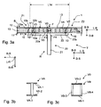
- FIG. 3 shows an embodiment of a combination of a support structure T according to the invention with a support assembly, which may be in particular a total T-shaped rib assembly R, and a plank 22, according to the invention with an inner, an outer skin portion 11 and 12 and an intermediate this located schublast-receiving core layer 13 is designed.
- the FIG. 3 is a sectional view of a portion S3 of the flow body 1 of FIGS. 1 a and 1b, along the in the FIGS. 1 a and 1 b each registered line V3-V3 is formed to the respective registered viewing direction in the form of two arrows and is a schematic sectional view of a combination of a support structure according to the invention with a T-shaped rib arrangement and a B plating.
- the plating shell B is formed with an inner skin section 11 with respect to the flow body 1 and an outer skin section 12 and a shear-load-receiving core layer 13 located therebetween.
- reinforcing devices 10 or rib arrangement reinforcing profile parts can be inserted into the core layer 13 laterally of the rib arrangement R.
- the support structure T may also have a support arrangement, only a rib 21 without a plate-shaped connection piece 22, or a support arrangement which has only one plate-shaped connection piece 22.
- a support member 5, 6 and / or the rib assembly R forms on the plank B, one or more profile carrier or rib assembly reinforcing profile parts V0 are incorporated or integrated.
- profile carrier as carrier component-reinforcing profile or reinforcing profile parts or rib assembly reinforcing profile or reinforcing profile parts are arranged.
- connection region 14 is that region of the cladding shell B in the planar extension thereof which, in the thickness direction DB of the cladding shell B, covers or intersects the region which the support structure T or the support component 5, 6 or the support or rib arrangement R carries their side facing the plank B side bounded or within the limits of the respective support structure T is applied to the plank B.
- the side of the support structure T facing the cladding shell B is, in the exemplary embodiment shown, the side of the flange part R of the cladding shell B facing the cladding shell R.
- the profiled supports V0 connect the flange part 22 or the inner skin section 11 and the outer skin section 12 for stabilizing the planking shell B when damaged from the outside together.
- the at least one or the profile carrier V0 may be formed as elongated or plate-shaped reinforcing profile carrier.
- the profile carrier V0 can extend in a reference longitudinal direction, which is directed in the longitudinal extent of the respective support structure T.
- the longitudinal extent of the support components after the FIG. 1 a runs along the adjoining edge region of the planking shell B, so that in this regard the reference longitudinal direction of the profile support V0 runs along the edge region of the planking shell B.
- the reference longitudinal direction of a support assembly or a rib assembly R extends in the direction of the longitudinal extent thereof, and in particular along the support assembly longitudinal direction LR, ie parallel to, or oblique to, the support assembly / length direction LR.
- these can in particular in a reference longitudinal direction seen, in the embodiment shown, the rib assembly longitudinal direction LR, be juxtaposed and run side by side.
- the reference longitudinal direction is the direction of extension of a region to be reinforced by means of the profile carrier V0 or to be stabilized for load cases.
- the region to be reinforced or stabilized may be the connection region of a carrier structure T, such as a carrier component 5, 6 or a rib arrangement R.
- This can be, in particular, the connecting region of the flange part 22 and the plank B.
- the rib assembly longitudinal direction LR is understood to mean the direction that runs along the longitudinal extent of the plating shell B and the longitudinal direction of the rib 21. In providing a plurality of ribs, the rib arrangement longitudinal direction LR may be particularly along the longitudinal direction of one of these ribs or a main rib.
- the rib arrangement transverse direction QR is to be understood as the direction which runs perpendicular to the rib arrangement longitudinal direction LR and transversely to the longitudinal extension of the lining shell B and in the width direction, ie the main extension of the rib 21.
- the rib assembly width direction BR that is perpendicular to the rib assembly longitudinal direction LR and the rib assembly transverse direction QR.
- a plurality of rib assembly reinforcing profile parts V0 arranged in the rib assembly width direction BR are arranged side by side, as seen in the rib assembly longitudinal direction LR.
- an embodiment of the rib assembly R is shown, in which over the entire connection region of the flange part 22 and the planking shell B Rib assembly reinforcing profile parts V0 are distributed.
- cross-section of an embodiment of the rib assembly R a total of ten rib assembly reinforcing profile parts V0 in the rib assembly longitudinal direction LR are juxtaposed seen.
- FIG. 3a total of ten rib assembly reinforcing profile parts V0 in the rib assembly longitudinal direction LR are juxtaposed seen.
- the outer reinforcing profile beams V0 seen on the rib assembly longitudinal direction LR are designated by reference numerals V1, V3 and V2, V4, respectively.
- the rib assembly profile parts V0 can in particular be distributed at uniform intervals in the entire region of the flange part 22 or over a portion of the flange part 22.
- this (reference VA) of two profile plates VA-1, VA-2, one of which is connected to the inner skin portion 11 and the other with the outer skin portion 12, and a connecting thereto support rib VA-3 be formed so that its profile cross section is a double-T profile cross-section.
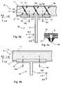
- FIG. 4a is a sectional view of the area S3 of the flow body of FIGS. 1 a and 1 b shown along in the FIGS. 1 a and 1 b each registered line V3-V3 is formed to the respective registered viewing direction in the form of two arrows and a schematic sectional view of a combination of a support structure according to the invention with a T-shaped rib arrangement and one with an inner, an outer skin portion 11th , 12 as well as a plating shell B designed between these and a thrust load-receiving core layer 13, in which the connection part 22 with the planking shell B is fastened to the inner skin section 12 by means of connecting elements 16.
- the connecting elements 16 with the position lines 15a and 15b is shown.
- connection part 22 and the outer skin portion 12 in particular each form at least one extending in the width direction BB series of connecting elements 16 can.
- the rows can in particular also run parallel to one another. Also, the rows of in be formed at regular intervals spaced-apart connecting elements 16.
- no profile support as according to the embodiment of the FIG. 3a be arranged between the skin sections 11, 12.
- the arrangement of connecting elements 16 for connecting the connecting part 22 with the outer skin portion 12 may as in the embodiment of the FIG. 4a be provided.
- FIG Figure 4c An example of the connecting element 16 which can be used according to the invention is shown in FIG Figure 4c a rivet that attaches the connector 22 to the main portion 12.
- connection region provision can be made, in particular, for the inner skin section on which the connection part 22 rests to have a greater material thickness than the inner skin section to the side of the connection region.
- this thickening with regard to its areal extent may be in a region which deviates from the edge profile of the connection region by at most 10 times the thickness of the cladding shell. This increase in thickness can be realized by arranging further layers in this region extending flatly on the surface of the inner skin section facing the core layer and / or on the outer surface of the planking shell.
- reinforcing parts 10a, 10b or reinforcing devices 10 can be seen in a row in the width direction BR of the rib arrangement or viewed in the width direction of the carrier component next to one another and / or in the longitudinal direction LR Rib arrangement or be arranged in the longitudinal direction of the support member. In these cases, as in the FIG.
- the reinforcing members generally extend in the thickness direction of the plating shell B or at an angle thereto and may be located within the core layer 13 such that their ends F1 are spaced from the skin sections 11, 12 or one of their ends F1 is spaced from one of the skin sections 11, 12 or the reinforcing members may be located so as to respectively connect the inner and outer skin portions 11, 12, that is, to partially penetrate into the inner and / or outer skin portions 11, 12.
- the inner skin portion 51 and / or the outer skin portion 52 may each be formed of a plurality of skin layers and / or at least a portion of the reinforcing devices 10, 10a, 10b, 10c, 10d; 10e, 10f may be arranged such that their ends F1 or one of the ends F1 thereof penetrate the inner skin portion 51 and / or the outer skin portion 52 respectively at least the first skin layer. In general, therefore, the reinforcing parts at least partially penetrate the thrust-receiving core layer 13.
- the reinforcing profile carrier VB of two profile plates VB-1, VB-2, one of which is connected to the inner skin portion 11 and the other with the outer skin portion 12, and two connecting these support ribs VB-3, VB-4 for forming be formed of a box profile cross-section.
- the arrangement of the reinforcing parts and / or reinforcing device 10 along the rib arrangement R is achieved that damage the plank B z. B. in the form of cracks in the schublast-receiving core layer 13 in the region of the rib assembly R is not transferred or to a reduced extent on the next to the rib arrangement R extending flat area of the plank B shell.
- the arrangement of the reinforcement device 10 along the fin arrangement R achieves that Damage to the planking shell B z. B. in the form of cracks in the Schublastaufhouseden core layer 13 in addition to the rib arrangement R extending flat area of the plank B on the region of the rib arrangement R located area of the plating shell B is not transmitted or reduced extent.
- At least one reinforcement device 10 is arranged between rib arrangement reinforcement profile parts V0 of the rib arrangement R arranged next to one another in the rib arrangement longitudinal direction LR.
- This constellation can be provided in the rib assembly longitudinal direction LR several times in succession. Also, between several, so z.
- at least one reinforcing device 10 according to the invention may be arranged between two, three or four outer rib assembly reinforcement parts.
- the reinforcing device 10 and the respective associated rib assembly reinforcing parts can also be arranged offset in relation to one another as seen in the rib arrangement transverse direction QR.
- these constellations preferably occur repeatedly in the rib assembly longitudinal direction LR and can be distributed over the length of the rib assembly R in the plating cup B.
- FIG. 3 schematically a cracking in the foam core 13 is shown: an object F1 strikes with an impulse F on the planning shell B, the resulting cracks in the foam core 13 are shown by the reference numerals F3 and F4.
- reinforcement parts and / or at least one reinforcement device 10 may also be used instead of rib arrangement reinforcement profile parts V0 may be disposed in the plating tray according to one of the ways described herein.
- the reinforcing devices 10 can generally be formed in each case from at least one reinforcing part.
- a reinforcing member as a pin-shaped reinforcing member with z. B. round or rectangular cross-sectional shape.
- the reinforcing devices 10 are each formed from at least one reinforcing part 10a, 10b, 10c, 10d, 10e, 10f.
- a reinforcement part 10a, 10b, 10c, 10d, 10e, 10f may in particular be formed as an elongated and / or plate-shaped element.
- the reinforcing parts 10a, 10b, 10c, 10d, 10e, 10f thus be designed in particular pin-shaped or needle-shaped.
- the reinforcing parts 10a, 10b, 10c, 10d, 10e, 10f respectively shown are designated by the reference numerals 10a, 10b, 10e or 10f.
- FIG. 5c illustrated embodiment of the combination of Beplankungsschale B and a support member 5, 6 and / or the rib assembly R on the plank B can be provided that in the terminal portion 14 of the plank B and optionally in the width direction BR laterally adjacent to this reinforcing parts 10a, 10b, 10c, 10d, 10e, 10f or reinforcing devices 10 are arranged in particular according to the invention provided and / or described herein. It is provided in particular that in the connection area 14 no profile parts are used ( FIG. 5c ).
- reinforcing members 10a, 10b, 10c, 10d, 10e, 10f or reinforcing devices 10 may be arranged in a row in the width direction BR of the rib assembly or in the width direction of the support member adjacent to each other and / or in the longitudinal direction LR of the rib assembly or in the longitudinal direction of the support member be.
- reinforcing parts 10a, 10b, 10c, 10d, 10e, 10f be introduced in each X-shaped arrangement in the planking B.
- the reinforcing members generally extend in the thickness direction of the plating shell B or obliquely thereto and may be located within the core layer 13 in this manner be that their ends F1 are spaced from the skin portions 11, 12 or one of their ends F1 is spaced to one of the skin portions 11, 12, or the reinforcing members may be located so as to connect the inner and outer skin portions 11, 12, respectively , So in the inner and / or outer skin portion 11, 12 partially penetrate.
- the inner skin portion 51 and / or the outer skin portion 52 may each be formed of a plurality of skin layers and / or at least a portion of the reinforcing devices 10, 10a, 10b, 10c, 10d; 10e, 10f may be arranged such that their ends F1 or one of the ends F1 thereof penetrate the inner skin portion 51 and / or the outer skin portion 52 respectively at least the first skin layer. In general, therefore, the reinforcing parts at least partially penetrate the thrust-receiving core layer 13.
- the reinforcing members may be located in the plating tray B such that the angle between the longitudinal direction of the respective reinforcing member and the thickness direction of the plating tray at that location is within a range between 45 degrees and 10 degrees.
- the reinforcing devices 10 provided according to the invention can generally be arranged in a reference longitudinal direction, which in the exemplary embodiment shown is the rib arrangement longitudinal direction LR, arranged one behind the other. Furthermore, reinforcing parts V can also be arranged one behind the other, viewed transversely to the reference longitudinal direction or rib longitudinal direction LR. In this case, reinforcing parts and / or reinforcing devices 10 may be arranged in a plurality of juxtaposed rows of reinforcing parts and / or reinforcing devices 10. Such rows of reinforcing devices 10 may also intermesh ( FIG.
- reinforcing devices 10 in which the reinforcing devices 10 are overlapped in their extension in the reference longitudinal direction LR, wherein the reinforcing parts and / or reinforcing devices 10 may also be located spaced apart in the reference longitudinal direction LR , Thus, in particular, several rows of reinforcing parts can run next to one another.
- the reference direction with regard to the arrangement of reinforcing devices 10 or reinforcing parts is the direction of extension of a region to be reinforced by means of a plurality of reinforcing devices 10 or reinforcing parts or to be stabilized for load cases.
- This area is also referred to below as the reinforcement area or intermediate area Z.
- the reinforcing parts or the reinforcing devices can be arranged one behind the other along the reference longitudinal direction and in a row or in several rows next to one another.
- the pin-shaped elements can be arranged offset in relation to one another in a straight line one behind the other or in the rib arrangement longitudinal direction LR, ie also have a distance from one another transversely to the longitudinal extent of the plank B.
- reinforcing members 10a, 10b are disposed within two side regions Z1, Z2 of the plating shell B which extend in the rib assembly longitudinal direction LR and laterally along the lateral ends of the plating shell portion 14 and whose width is transverse to the rib assembly longitudinal direction LR and in the longitudinal extent of the plank B extends.
- reinforcing parts 10a, 10b are introduced in a reinforcing region, which are located within the plating shell section 14 and laterally along the lateral ends of the plating shell section 14 in the core layer 13.
- Such groups of amplification parts are designated by the reference symbols V3 and V4.
- the embodiments of the planking shell B according to the invention for influencing shear stresses and for preventing cracking in the core layer 13 can have a plurality of reinforcing devices 10 arranged at least in a reinforcement region or intermediate region Z of the planking shell B, each of a combination of at least two in a contiguous volume part V ( FIG. 2 ) of the plank B arranged reinforcing parts are formed.
- the at least one intermediate region Z of the cladding shell B is selected in size and position such that it does not stabilize the entire cladding shell B due to the external loads provided in the given application by the shear stresses arising in the respective intermediate region Z due to these loads due to the presence of the reinforcement parts cause crack formation in the core layer 13 of this intermediate region Z or stop cracking.
- the position and size of the at least one intermediate region Z and the type of arrangement of the reinforcing parts therein are preferably selected such that the risk of crack formation in the core layer 13 of the planking shell B is minimized not only within but also outside of the intermediate region Z.
- the position and size of the at least one intermediate region Z depends on the application case, ie the shape of the entire structural component with the plank B, with the associated assumed external loads.
- the reinforcing parts of the reinforcing devices 10 may be arranged in groups.
- each group of reinforcing parts 10a, 10b, 10c, 10d or 10e, 10f in a respective fictitious volume part V is formed in each case from a combination of at least two reinforcing parts 10a, 10b, 10c, 10d or 10e, 10f.
- a contiguous volume part V of the plank B are arranged a group of reinforcing parts.
- the reinforcing parts 10a, 10b, 10c, 10d or 10e, 10f of a group thereof each have a similar position or orientation within the plating shell B and each have a maximum deviation of 30 degrees the same orientation relative to the thickness direction DB of the plank B.
- the orientations of the reinforcing members of a group are provided cyclically relative to the other coordinate directions LB, BB of the plank B shell.
- FIG. 2 An example of a group of four amplifying parts 10a, 10b, 10c, 10d having cyclical orientation with each other is shown in FIG FIG. 2 shown.
- an embodiment of such a fictitious volume part V in the form of a cuboid with the edge lines K is shown.
- the longitudinal direction LZ of the intermediate region Z and the coordinate system of the planking shell with its coordinate axes LB, BB and DB shown.
- the arrangement of the reinforcing devices 10 is provided in particular in the longitudinal direction LZ of the intermediate region Z in succession.
- the reinforcing device 10 shown there is formed from a combination of four reinforcing parts 10a, 10b, 10c, 10d, wherein in the combination of the reinforcing parts 10a, 10b, 10c, 10d these each with a deviation of at most 10 degrees the same orientation with respect to the thickness direction DB of the plank B have and wherein the orientations of the reinforcing parts with respect to the other coordinate directions LB, BB of the plank B is cyclic.
- the amplification devices 10 or a plurality of amplification devices 10 according to the invention may generally be arranged along one, i.e., one side of, the other. parallel or angled, to the reference line or the rib assembly longitudinal direction L-R extending imaginary line behind each other and / or also transversely to the rib longitudinal direction L-R be offset from each other.
- a group of reinforcing parts may be formed of two reinforcing parts 10e, 10f, which are arranged in an X-shaped manner in an approximately X-shaped manner in the reference longitudinal direction.
- the plank B is thus at least a part of the reinforcing devices 10 of pairs of reinforcing parts 10 a, 10 b, 10 c, 10 d; 10e, formed 10f, the reinforcing members seen in the direction of a longitudinal extent of the paneling shell B seen in pairs X-shaped orientations.
- the two reinforcing parts can be arranged at a distance from one another or else rest against one another or be introduced into the paneling shell B as a cross-shaped structure.
- a plurality of pairs of the reinforcing devices 10 located on each of the two sides Z1, Z2 are oriented to each other such that each one of these pairs forms an X-shaped reinforcing device as seen in the rib arrangement longitudinal direction L-R.
- the reinforcement devices 10 can be designed and constructed in various ways. According to an embodiment of the present invention, it is provided that the reinforcing devices 10 are formed of a plurality of combinations of pin-shaped reinforcing members 10e, 10f located one behind the other as viewed in the rib assembly longitudinal direction LR, each pair of reinforcing members 10e, 10f in one of the present invention Volume part V is arranged. Also, a part or all of the reinforcing parts inserted in a cladding shell B or a portion thereof may be made needle-shaped.
- the reinforcing parts can be provided at one of their ends or at both of their ends with a foot-like widening or a hook, which can be provided for positioning and / or spatial fixation or anchoring within the planning shell B.
- An advantage of this design of Reinforcing parts may be that in the occurrence of an external dynamic damage load, the respective reinforcing parts remain fixed in the plank B.
- the reinforcing devices may be formed of a plurality of combinations of plate-shaped reinforcing members (not shown in the figures) each extending in their first longitudinal extent between that between the inner skin portion 11 and the outer skin portion 12 and extending through between extend this located thrust load-receiving core layer 13 therethrough.
- These plate-shaped reinforcing parts extend in their longitudinal extent extending perpendicular to the first longitudinal extent in the rib arrangement longitudinal direction L-R.
- the z. B. pin-shaped or plate-shaped reinforcing parts 10e, 10f in particular of respective pairs thereof may abut each other.
- pin-shaped or plate-shaped reinforcing parts 10e, 10f, in particular, of respective pairs thereof may be spaced from each other in the rib arrangement longitudinal direction L-R. According to one embodiment, it may be provided that the distance of the pin-shaped or plate-shaped reinforcing parts 10e, 10f of each one of them is at most 1.5 times the thickness of the plating shell B at the respective location.
- the reinforcing devices in the case of forming the reinforcing devices as plate-shaped reinforcing parts, two or more of them may be arranged to interlock with each other also in the rib arrangement longitudinal direction L-R.
- the reinforcing members and / or reinforcing devices 10 of the invention may also extend through the inner skin portion 11 and the outer skin portion 12, or each end portion thereof be anchored.
- reinforcing devices 10 or a plurality thereof may be provided with their respective end portions facing the skin portions on the inner skin portion 11 and the outer skin portion 12 abut or at a distance to each end.
- the reinforcing devices 10; 10a, 10b, 10c, 10d; 10e, 10f are arranged in the plank B in such a way that their ends F1 at least partially project through the inner skin section 11 and / or the outer skin section 12, as shown in FIGS FIGS. 5a, 5b . 7, 8 . 9, 10a, 10b and 11 is shown.
- the inner skin portion 11 or 51 (FIG. FIG. 11 ) and / or the outer skin portion 12 or 52 (FIG. FIG. 11 ) may each be formed of several skin layers (not shown in the figures).
- At least a part of the reinforcement devices 10a, 10b, 10c, 10d is arranged in the plating shell B in such a way that their ends F1 are the inner skin section 11 or 51 and / or the outer skin section 12 or 52 each at least partially protrude.
- the reinforcing members may generally be formed according to the invention of a metallic material and / or of a non-metallic material and in particular of a fiber composite plastic. Carbon, fiberglass, quartz, Kevlar and / or ceramic can be used as non-metallic material.
- the thrust load-receiving core layer 13 has at least one core layer reinforcement area 37 and preferably a plurality of core layer reinforcement areas 37 (FIG. FIG. 4 ), with or with which a plurality of shear-load-receiving core layer sections 33a arranged side by side in the longitudinal extent of the thrust-receiving core layer 33 or the foam layer are connected.
- Each core layer reinforcement region 37 extends in a longitudinal direction LV (FIG. FIG. 3 ) Transversely to the longitudinal extent of the thrust load-receiving core layer 13 therethrough and extends between the inner skin portion 11 and the outer skin portion 12.
- the edge lines of the individual thrust-receiving core layer sections 33a and the course of the core layer reinforcement regions 37 are displayed.
- the courses of the core-layer reinforcement regions 37 are provided such that rectangular shear-load-receiving core-layer sections 33a result, or conversely, the core layer is composed of core-layer sections 33a which are interconnected via core-layer reinforcement sections 37.
- the core layer reinforcing portion 37 is bonded to the inner skin portion 11 and the outer skin portion 12 so that the core layer reinforcing portion 37 is fixed to the inner skin portion 11 and the outer skin portion 12.
- the thickness 17a of the core layer reinforcing region 37 is between 0.1 and 2.0 times the width of the plating shell B at this point, the thickness being measured perpendicular to the longitudinal extent of the planking.
- the reinforcing region is formed of a material having at least two-fold rigidity as the thrust-receiving core layer 13.
- the core-layer reinforcing region 37 may be formed in particular of resin.
- a plurality of reinforcing members 10 arranged one after the other in accordance with an embodiment of the invention and arranged one behind the other along the rib assembly longitudinal direction LR project through the at least one core layer reinforcement region 37.
- the core layer reinforcing region 37 may extend in particular in its longitudinal direction along the rib assembly longitudinal direction LR and along a portion or along the entire length of the rib assembly R.
- the core layer reinforcement area 37 may run parallel or at an angle to the rib assembly longitudinal direction LR.
- At least one core layer reinforcement region 37 with reinforcement parts and / or reinforcement devices arranged thereon can be provided in particular in at least one of the two side regions Z1, Z2 extending in the rib arrangement longitudinal direction LR.
- a plurality of reinforcing devices 10 may be arranged according to an embodiment of the invention.
- FIG. 7 11 an embodiment in which an assembly or a pair of reinforcing members 10, 10e, 10f project through a core layer reinforcing portion 37 in an X-shaped configuration, respectively, wherein a center portion of reinforcing members 10e, 10f is located within the core layer reinforcing portion 17, respectively .
- the two reinforcing parts of an X-shaped arrangement thereof are provided with reference numerals 10e and 10f.
- a plurality of X-shaped arrangements of reinforcement parts 10 are arranged in the longitudinal direction of the core layer reinforcement region 37 as a reference longitudinal direction one behind the other and adjacent to one another or adjoining and / or at intervals.
- X-shaped arrangements 10 - 1, 10 - 2 are arranged one behind the other along the rib arrangement longitudinal direction LR and along the longitudinal direction of the core layer reinforcement area 37, on both sides of the core layer reinforcement area 37 X-shaped arrangements 10-1, 10-2 are arranged one behind the other.
- FIG. 8 an embodiment is shown in which at the same point in the longitudinal direction of the core layer reinforcing region 17 and in relation to this one each opposite an X-shaped arrangement or a pair 10-1, 10-2 of reinforcing members 10 is arranged.
- the "X-shaped" arrangement of reinforcing parts referred to herein are arranged, in particular in the respective reference longitudinal direction, at a distance from one another, so that the FIGS. 7 and 8 as well as in the FIGS. 9, 10a and 10b one of the amplifying apparatus of the respective pair of amplifying members and / or amplifying apparatuses shown in phantom to indicate that this amplification device is located behind the respective drawing plane.
- the two reinforcing parts of an X-shaped arrangement thereof are provided with reference numerals 10e and 10f.
- the longitudinal direction of the core-layer reinforcing region 37 extends from the viewer of FIG.
- first X-shaped arrangement 10-1 on the left side and a second X-shaped arrangement 10-2 on the right side of the core layer reinforcing region 37 each protrude through the
- the reinforcing parts of an X-shaped arrangement of reinforcing parts may also be situated next to, ie at a distance from, the reinforcing area.
- the outer ends facing the core layer reinforcement region 37 are located at a distance of at most the simple thickness of the cover shell B at this location.
- the X-shaped arrangements 10 - 1, 10 - 2 may be situated alternately on one side and the other side of the core layer reinforcement area 37 seen opposite to the longitudinal direction of the core layer reinforcement area 37.
- connection of the two reinforcing parts 10e, 10f may be provided in such a way that they are connected to one another in a rotationally fixed manner in order to receive shear stresses occurring in particular in the thrust-receiving core layer 13 and / or to stop or prevent cracks occurring therein.
- the on hand of the FIGS. 7 and 8 described embodiments of the invention cause damage in the thrust-receiving core layer 13, if they occur on a first of the sides of the core layer gain region 37, not through the core layer reinforcement region 37 to a second, the first side opposite side can walk over.
- the arrangement and / or configuration of the reinforcing members and / or reinforcing devices may be the same for the various aspects of the invention.
- at least a part of the reinforcing devices 10; 10a, 10b, 10c, 10d; 10e, 10f are arranged in the core layer end region 56 such that their ends F1 at least partially project through the inner skin section 11 and / or the outer skin section 12, as shown in FIGS FIGS. 5a, 5b . 7, 8 . 9, 10a, 10b and 11 is shown.
- the inner skin portion 11 or 51 (FIG. FIGS. 6 to 10 ) and / or the outer skin portion 12 or 52 (FIG. FIGS.
- the reinforcement devices 10a, 10b, 10c, 10d is arranged in the plating shell B in such a way that their ends F1 are the inner skin section 11 or 51 and / or the outer skin section 12 or 52 each at least partially protrude.
- a plurality of reinforcing parts 10; 10a, 10b, 10c, 10d; 10e, 10f, the reinforcing region 37 each at least partially protrude.
- each reinforcing device can be formed from a group of reinforcing parts 10a, 10b, which in particular have an X-shaped arrangement.
- a plurality of reinforcing-part pairs arranged in an X-shape can be arranged one behind the other in the reference longitudinal direction ( FIG. 9 ).
- a plurality of rows of such reinforcing devices 10 can also be arranged, the rows of reinforcing devices being transverse to the Reference longitudinal direction seen are arranged side by side.
- juxtaposed rows of reinforcing devices 10-1, 10-2 can be designed such that the longitudinal extent of reinforcing parts, whose ends converge towards one another, overlap one another in the reference longitudinal direction.
- a flow body is provided with a structural component according to one of the described embodiments.
- the structural component according to the invention is a main load-bearing structural part and thus also the planking shell as well as the rib arrangement is a main load-bearing structural component.
- a further aspect of the invention relates to the region of the paneling shell B that extends in a planar manner between rib arrangements R and is described below with reference to FIGS Figures 6a and 6b described embodiments described.
- a structural component 1 of a flow body is provided with at least one cladding shell B for forming a flow surface on the outside of the structural component 1 and a support structure T for fixing the respective cladding shell B, wherein the cladding shell B - as described above with reference to the FIGS.
- the thrust load-receiving core layer 33 extending between the carrier components T and the rib arrangement R and located between the inner and outer skin sections 31, 32 is composed of a plurality of shear-load-receiving core layers juxtaposed in the longitudinal extent of the shear-load-receiving core layer 33 or the foam layer Formed sections 33a.
- the thrust load-receiving core layer sections 33a are connected to each other on the adjacent sides by a core layer reinforcement section 37 which extends in its longitudinal direction LV (FIG. FIGS. 6a, 6b ) extends transversely to the longitudinal extent of the thrust receiving core layer 33 therethrough.
- the course of the core layer reinforcing regions 37 in the longitudinal extent of the plating shell B and thus of the core layer sections 33a can be provided in various ways.
- the core layer portions 33a corresponding to the course of the core layer reinforcing regions 37 in the longitudinal extent of the skin B are in the embodiment according to the FIG. 6a checkered and in the embodiment of the FIG. 6b opposite to a checkerboard arrangement in a longitudinal direction offset from each other.
- the core layer reinforcement regions 37, seen in the longitudinal extent of the cladding shell B run in such a way that they impinge on a side edge or on a corner of core layer sections 33a provided in a cuboidal manner.
- the core layer reinforcement region 37 can extend between the inner skin section 31 and the outer skin section 32.
- provision may in particular be made for the core-layer reinforcement region 37 to be connected to the inner skin section 31 and the outer skin section 32, so that the core-layer reinforcement region 37 is fastened to the inner skin section 31 and the outer skin section 32.
- the core layer reinforcing region 37 may be formed of a material having at least two times the rigidity of the core layer reinforcing region 37.
- the thickness 17a of the core layer reinforcing region 37 is between the 0.1 and the second , 0 times the width of the plank B at this point, wherein the thickness is measured perpendicular to the longitudinal extent of the Plankschaleschale.
- the core layer reinforcing region 37 may be formed in particular of resin.
- FIG. 6 an embodiment of the structural component according to the invention is shown, with dashed lines, the edge lines of the individual thrust-receiving core layer sections 33a and the course of the core layer gain regions 37 are displayed.
- the support structure T can in particular consist of at least two carrier components 5, 6 (not in FIG. 1) extending in each case along a longitudinal direction LS of the structural component 1 FIG. 6 shown) and at least one with the Beplankungsschale B associated rib assembly R for planar support of the planking shell B to the support structure T be formed ( FIGS. 1a, 1b ).
- the rib arrangement R can be designed T-shaped in particular with regard to its cross section.
- An embodiment of a rib assembly R according to the invention is in the FIG. 2 and includes: a rib 21 and an adjoining flange portion 22 which is connected to and fixed to a surface portion of the plating tray B.
- the length of the flange part 22 extends in a rib arrangement longitudinal direction LR
- the width of the flange part 22 extends in a rib arrangement transverse direction QR
- the rib 21 protruding from the flange part 22 in a rib arrangement width direction BR perpendicular to the rib arrangement longitudinal direction LR and the rib arrangement transverse direction QR is directed ( FIG. 3 ).
- the carrier components 5, 6 can be formed in particular according to embodiments, which on hand of FIGS. 1 and 2 have been described.
- the courses of the core layer reinforcing regions 37 are provided so as to give rectangular push load receiving core layer portions 33a.
- a plurality of core layer reinforcing regions 37-1, 37-2, 37-3 extending along the rib assembly longitudinal direction LR.
- a local angle deviation of at most 30 degrees with respect to the orientation lies between the orientation of the core layer reinforcement regions 37-1, 37-2, 37-3 running in the rib arrangement longitudinal direction LR the local rib assembly longitudinal direction LR or the longitudinal direction of the rib assembly R occurs.
- the core layer reinforcement regions 37 may be curvilinear or rectilinear. In the FIG.
- the thrust load-receiving core layer longitudinal direction LV is entered only for a core layer reinforcement region 37. Further, core-core reinforcing regions 37-4 extending transversely to the core-layer reinforcing regions 37-1, 37-2, 37-3 extending in the rib-assembly longitudinal direction LR are provided.
- reinforcing devices according to the invention are integrated in the thrust-receiving core layer 33 along a surrounding region Z of a plurality of core-layer reinforcement regions 37 of the cladding shell B.
- FIG. 6 For example, such a surrounding area or intermediate area is provided with the reference Z).
- the reinforcing devices 10 are arranged one behind the other in the longitudinal direction LV of the reinforcing region or along the longitudinal direction of the intermediate region Z.
- the surrounding region Z for the arrangement of the reinforcing devices 10 may extend along the longitudinal extent thereof on both sides of the core layer reinforcing region 37 and up to a maximum of twice the thickness of the plating shell B at the respective location of the core layer reinforcing region 37 ,
- the reinforcing members and / or reinforcing devices 10 may be integrated together with the core layer reinforcing portion 33 in the plank B, as described above with reference to FIGS Figures 2 and 3 so that the same reference numerals are used for components of similar function.
- FIGS. 6 and 7 Two embodiments of reinforcing devices 10 disposed adjacent and along core layer reinforcement regions 37 are shown.
- the embodiments of the in the FIGS. 7 and 8 shown amplifying devices 10 and their arrangement are analogous to the amplifying devices 10 and their arrangement executed as shown in the Figures 2 or 3 are shown.
- the design and arrangement of the reinforcing devices 10 or the reinforcing members may, as in the on hand of the Figures 3 and 4 be described embodiments described.
- a plurality of reinforcing parts 10 which are embodied one after the other in accordance with an embodiment of the invention and arranged one behind the other along the reinforcing region longitudinal direction LV, respectively project through the core layer reinforcing region 37.
- FIG. 8 11 an embodiment in which an assembly or pair of reinforcing members 10e, 10f project through a core layer reinforcing portion 37 in an X-shaped configuration, each having a center portion of a reinforcing member 10 located inside the core layer reinforcing portion 37 is shown.
- reinforcement parts 10 can also be located in the reinforcement region longitudinal direction LV next to the core layer reinforcement region 37.
- the two reinforcing parts of an X-shaped arrangement thereof are provided with reference numerals 10e and 10f.
- a plurality of X-shaped arrangements of reinforcing parts 10 are arranged one behind the other in the longitudinal direction of the core layer reinforcing area 17 and in this case adjoining one another and / or at intervals from one another.
- X-shaped arrangements 10 - 1, 10 - 2 are arranged one behind the other along the rib arrangement longitudinal direction LR and along the longitudinal direction of the core layer reinforcement area 37, on both sides of the core layer reinforcement area 37 X-shaped arrangements 10-1, 10-2 are arranged one behind the other.
- FIG. 8 an embodiment is shown in which at the same point in the longitudinal direction of the core layer reinforcing region 37 and in relation to each other in each case an X-shaped arrangement or a pair 10-1, 10-2 of reinforcing members 10 is arranged.
- the two reinforcing parts of an X-shaped arrangement thereof are provided with reference numerals 10e and 10f.
- the longitudinal direction LV of the core-layer reinforcing region 17 extends from the viewer of FIG. 6 Starting perpendicularly into the plane of the page and there is a first X-shaped arrangement 10-1 on the left side and a second X-shaped arrangement 10-2 on the right side of the core layer reinforcing area 17.
- the reinforcing parts of an X-shaped arrangement of reinforcing parts may also be situated next to, ie at a distance from, the reinforcing area.
- the outer ends facing the core layer reinforcement region 37 are located at a distance of at most the thickness of the cover shell B at that location.
- the X-shaped arrangements 10 - 1, 10 - 2 may be situated alternately on one side and the other side of the core layer reinforcement area 37 seen opposite to the longitudinal direction of the core layer reinforcement area 37.
- FIGS. 7 to 10b described embodiments of the invention cause damage in Schublastaufumblede core layer 33, if they occur on a first of the sides of the core layer gain region 37, can not walk over the core layer gain region 37 to a second, the first side opposite side.
- FIGS. 9 and 10 shows in the inner region 50 of the planking shell B: the paneling shell B designed as a sandwich component with an inner skin section 51, an outer skin section 52 and a shear load-receiving core layer 53 between them, which flattens the inner 51 and outer 52 skin sections connects with each other.
- the properties of these structural components are as described above.
- FIGS. 9 and 10 For some components and components of the embodiment shown, the same reference numerals as in the preceding figures are used, when reference is made to the respective functionalities or properties.
- the plating shell B is adapted to be mounted to a support member having an outer edge portion 60 with an outer edge 61 comprising: a core layer free terminal portion 63 extending along the edge 61, with the inner skin portion 51, the outer skin portion 52, and one between them
- a transition region 62 is provided, seen in the inner region 50 of the schublast-receiving core layer 63 ends, ie in which the outer edge 55 of the thrust load-receiving core layer 53 is located or runs. From the comparison of FIGS. 8 and 9 can be taken that the edge 61 and the edge 55 along the longitudinal direction LS of the structural component 1 extends and the connection portion 63 extends from the inner region 50 in the width direction BS of the structural component 1.
- a region 66 may be provided in which the thickness of the monolithic intermediate layer is reduced towards the outer edge 61 in order to reduce the cross-sectional thickness of the cladding shell.
- reinforcing devices 10 are integrated in a core layer end region 56 along the outer edge section 60 of the planking shell B, which protrude through the shear-load-receiving core layer 53.
- the reinforcing device can as hand on the FIGS. 4 and 5 or 7 and 8 be executed described.
- an X-arrangement of reinforcement parts 10e, 10f can be used.
- two X-arrays 10-1 and 10-2 arranged in succession in the width direction BS of the structural component 1 are arranged.
- at least one reinforcement part 10 and in particular at least one X arrangement of reinforcement parts 10 can be arranged.
- the longitudinal direction of the core layer reinforcing region 17 extends from the viewer of FIG. 9 Starting perpendicularly into the plane of the page and there is a first X-shaped arrangement 10-1 on the left side and a second X-shaped arrangement 10-2 on the right side of the core layer reinforcing area 17.
- the reinforcing members of an X-shaped arrangement of reinforcing members may also be located adjacent to, ie, at a distance from the reinforcing region.
- the outer ends facing the core layer reinforcement region 17 are located at a distance of at most the thickness of the cover shell B at this location.
- the X-shaped arrangements 10 - 1, 10 - 2 may be located alternately on one side and the other side of the core layer reinforcement area 17, as seen in the longitudinal direction of the core layer reinforcement area 17.
- connection of the two reinforcing parts 10e, 10f may be provided such that they are non-rotatable with each other are connected to accommodate particular occurring in the thrust-receiving core layer shear stresses.
- FIGS. 3 and 3b, 4b described embodiments of the invention cause damage in the thrust load-receiving core layer 13, if they occur on a first of the sides of the core layer reinforcing region 17, do not migrate through over the core layer reinforcing region 17 to a second, the first side opposite side can.
- the plank B according to this aspect of the invention can in particular be taken up by and attached to a support structure T, as shown in FIGS FIGS. 1a, 1b and 2 or the FIGS. 5a, 5b, 5c is shown.
- the planking B between carrier components 5, 6 and the rib assembly R extends, as with the hand FIGS. 1 a and 1 b has been described above.
- the thrust load-receiving core layer 53 comprises a plurality of shear-load-receiving core layer sections (not shown in FIG. 1) arranged side by side in the longitudinal extension of the thrust load-receiving core layer 53 FIG. 9 or 10 shown), as shown by the hand FIGS.
- the schublast-receiving core layer sections are there - as on hand FIG. 6 are connected to each other on the adjacent sides by a core layer reinforcement region 37 which extends in the longitudinal direction LV of the reinforcement region (FIG. FIG. 6 ) extends transversely to the longitudinal extent of the thrust load-receiving core layer 33 and 63 therethrough.
- the core layer end region 56 for the arrangement of the reinforcement devices may extend from the edge of the core layer end to a maximum of four times the thickness of the cover shell B at the edge of the core layer end.
- the arrangement and / or configuration of the reinforcing members and / or reinforcing devices may be the same for the various aspects of the invention.
Landscapes
- Engineering & Computer Science (AREA)
- Aviation & Aerospace Engineering (AREA)
- Mechanical Engineering (AREA)
- General Physics & Mathematics (AREA)
- Pathology (AREA)
- Life Sciences & Earth Sciences (AREA)
- Chemical & Material Sciences (AREA)
- Analytical Chemistry (AREA)
- Biochemistry (AREA)
- General Health & Medical Sciences (AREA)
- Physics & Mathematics (AREA)
- Immunology (AREA)
- Health & Medical Sciences (AREA)
- Architecture (AREA)
- Civil Engineering (AREA)
- Structural Engineering (AREA)
- Laminated Bodies (AREA)
- Lining Or Joining Of Plastics Or The Like (AREA)
- Lining And Supports For Tunnels (AREA)
- Laying Of Electric Cables Or Lines Outside (AREA)
- Body Structure For Vehicles (AREA)
- Connection Of Plates (AREA)
Claims (16)
- Coque de planchéiage qui porte la charge principale (B) pour un élément de structure (1) d'un corps d'écoulement, la coque de planchéiage (B) étant formée comme un sandwich et à partir d'une portion d'enveloppe intérieure (11, 31, 51), d'une portion d'enveloppe extérieure (12, 32, 52) ainsi que d'une couche centrale (33) située entre celles-ci, qui absorbe la charge de poussée, qui relie la portion d'enveloppe intérieure et la portion d'enveloppe extérieure (11, 31, 51 ; 12, 32, 52) l'une à l'autre par leur surface, cependant que plusieurs dispositifs de renforcement (10 ; 10a, 10b, 10c, 10d ; 10e, 10f) sont intégrés dans la coque de planchéiage (B) dans la couche centrale, dispositifs qui traversent respectivement au moins 85 % de la couche centrale qui absorbe la charge de poussée (13) dans le sens de son épaisseur pour améliorer la résistance à la fissuration de la coque de planchéiage (B) et/ou pour obtenir une réduction des dommages existants ou qui se forment,
caractérisée en ce que
la couche centrale qui absorbe la charge de poussée (33) est formée par plusieurs portions de couche centrale (33a), placées l'une à côté de l'autre dans l'extension longitudinale de la couche de mousse, qui sont reliées l'une à l'autre respectivement sur les côtés adjacents l'un à l'autre par une zone de renforcement de couche centrale (37) qui s'étend transversalement par rapport à l'extension longitudinale de la couche centrale (33) en la traversant, cependant que la zone de renforcement (37) est formée en un matériau qui présente une rigidité au moins du double de celle de la couche centrale qui absorbe la charge de poussée (33) et que plusieurs parties de renforcement (10 ; 10a, 10b, 10c, 10d ; 10e, 10f) traversent la zone de renforcement (37) respectivement au moins partiellement. - Coque de planchéiage qui porte la charge principale (B) selon la revendication 1,
caractérisée en ce que la zone de renforcement de la couche centrale (37) est formée en résine. - Coque de planchéiage qui porte la charge principale (B) selon la revendication 1 ou 2, caractérisée en ce que des parties de renforcement (10 ; 10a, 10b, 10c, 10d ; 10e, 10f) sont mises en place avec une extrémité dans la zone de renforcement (37) et s'étendent avec le reste de leur surface dans la couche centrale qui absorbe la charge de poussée (33).
- Coque de planchéiage qui porte la charge principale (B) selon l'une des revendications 1 à 3, caractérisée en ce que des dispositifs de renforcement (10) sont intégrés dans la couche centrale qui absorbe la charge de poussée (33) de la coque de planchéiage (B) le long d'une zone environnante (Z) d'une multitude de zones de renforcement de la couche centrale (37).
- Coque de planchéiage qui porte la charge principale (B) selon la revendication 4, caractérisée en ce que la zone environnante (Z) pour l'arrangement des dispositifs de renforcement (10) s'étend des deux côtés de la zone de renforcement de la couche centrale (37) jusqu'à une distance d'au maximum dix fois l'épaisseur de la coque de planchéiage (B) sur l'endroit respectif de la zone de renforcement de la couche centrale (37).
- Coque de planchéiage qui porte la charge principale (B) selon l'une des revendications 1 à 5, caractérisée en ce que plusieurs rangées de parties de renforcement sont placées l'une derrière l'autre dans le sens longitudinal le long d'une zone environnante (Z) d'au moins une zone de renforcement de la couche centrale (37), cependant que les rangées de parties de renforcement sont placées de telle manière que leurs parties de renforcement se peignent l'une dans l'autre, ceci étant vu dans la direction de l'extension longitudinale de la portion marginale extérieure (60) de la coque de planchéiage (B).
- Coque de planchéiage qui porte la charge principale (B) selon l'une des revendications 1 à 6, caractérisée en ce que l'angle entre le sens longitudinal de la partie de renforcement respective et le sens de l'épaisseur de la coque de planchéiage à cet endroit se situe au sein d'une plage entre 45 degrés et 10 degrés.
- Coque de planchéiage qui porte la charge principale (B) selon l'une des revendications 1 à 7, caractérisée en ce que la portion d'enveloppe intérieure (11, 31, 51 ; 12) et/ou la portion d'enveloppe extérieure (12, 32, 52) est formée respectivement par plusieurs couches d'enveloppe.
- Coque de planchéiage qui porte la charge principale (B) selon l'une des revendications 1 à 8, caractérisée en ce qu'au moins une partie des dispositifs de renforcement (10 ; 10a, 10b, 10c, 10d ; 10e, 10f) est placée de telle manière que leurs extrémités (F1) traversent la portion d'enveloppe intérieure (11, 31, 51) et/ou la portion d'enveloppe extérieure (12, 32, 52) respectivement au moins partiellement.
- Coque de planchéiage qui porte la charge principale (B) selon l'une des revendications 1 à 9, caractérisée en ce que des parties de renforcement (10 ; 10a, 10b, 10c, 10d ; 10e, 10f) sont placées en tant que dispositifs de renforcement (10) dans la coque de planchéiage (B) dans des groupes de parties de renforcement situés respectivement dans une partie de volume (V) de la coque de planchéiage (B), cependant que les parties de volume (V) sont placées l'une derrière l'autre le long d'une direction longitudinale (L-V), cependant que chaque groupe d'une partie de volume (V) est formé respectivement par une combinaison d'au moins deux parties de renforcement (10a, 10b, 10c, 10d ; 10e, 10f) dont les orientations diffèrent respectivement de maximum 30 degrés du sens de l'épaisseur (D-B) de la coque de planchéiage (B) et qui sont placées de manière régulière ou irrégulière autour d'un axe central de la partie de volume (V),
cependant que de préférence au moins une partie des dispositifs de renforcement (10) est formée par des paires de parties de renforcement (10 ; 10a, 10b, 10c, 10d ; 10e, 10f) dont les parties de renforcement présentent des orientations par paires en forme de X, ceci étant vu dans le sens de l'extension longitudinale de la portion marginale extérieure (60) de la coque de planchéiage (B),
cependant que de manière particulièrement préférée au moins une partie des dispositifs de renforcement (10) est formée par des paires de parties de renforcement (10 ; 10a, 10b, 10c, 10d ; 10e, 10f) dont les parties de renforcement présentent des orientations par paires en forme de X, ceci étant vu dans le sens de l'extension longitudinale de la portion marginale extérieure (60) de la coque de planchéiage (B) et une multitude de parties de volume (V) est placée l'une derrière l'autre avec un groupe de parties de renforcement (10 ; 10a, 10b, 10c, 10d ; 10e, 10f) le long d'au moins une zone de la portion marginale extérieure (60). - Coque de planchéiage qui porte la charge principale (B) selon l'une des revendications 1 à 10, caractérisée en ce que des parties de renforcement (10a, 10b, 10c, 10d ; 10e, 10f) sont configurées au moins partiellement en forme de broches,
cependant que de préférence une extrémité de parties de renforcement est pourvue respectivement d'un élargissement de type pied. - Coque de planchéiage qui porte la charge principale (B) selon l'une des revendications 1 à 10, caractérisée en ce que des parties de renforcement (10a, 10b, 10c, 10d ; 10e, 10f) sont configurées en forme d'aiguilles.
- Coque de planchéiage qui porte la charge principale (B) selon l'une des revendications 1 à 10, caractérisée en ce que des parties de renforcement (10a, 10b, 10c, 10d ; 10e, 10f) d'un dispositif de renforcement (10) sont configurées au moins partiellement en forme de plaques,
cependant que des parties de renforcement en forme de plaques d'un dispositif de renforcement (10) sont placées en étant de préférence engrenées l'une dans l'autre. - Coque de planchéiage qui porte la charge principale (B) selon l'une des revendications 1 à 13, caractérisée en ce que la couche centrale qui absorbe la charge de poussée (53) est formée en une mousse dans la zone d'extrémité de la couche centrale (56).
- Elément de structure (1) d'un corps d'écoulement avec au moins une coque de planchéiage qui porte la charge principale (B) selon l'une des revendications 1 à 14 et une structure de support (T) pour la fixation de la coque de planchéiage (B),'
cependant que de préférence la structure de support (T) est formée par au moins deux composants de support (5, 6) situés respectivement le long d'une direction longitudinale (L-S) de l'élément de structure (1) et par au moins un arrangement de nervures (R) situé entre ceux-ci et transversalement par rapport à ceux-ci et relié à la coque de planchéiage (B) le long de sa direction longitudinale (L-R) pour l'appui en surface de la coque de planchéiage (B) sur la structure de support (T). - Corps d'écoulement avec un élément de structure et une coque de planchéiage qui porte la charge principale (B) qui enveloppe celui-ci au moins par sections, cependant que la coque de planchéiage (B) est configurée selon l'une des revendications 1 à 14.
Applications Claiming Priority (9)
| Application Number | Priority Date | Filing Date | Title |
|---|---|---|---|
| US36585710P | 2010-07-20 | 2010-07-20 | |
| US36587310P | 2010-07-20 | 2010-07-20 | |
| US36588210P | 2010-07-20 | 2010-07-20 | |
| US36586310P | 2010-07-20 | 2010-07-20 | |
| DE102010027695A DE102010027695A1 (de) | 2010-07-20 | 2010-07-20 | Strukturbauteil mit zumindest einer hauptlast-tragende Beplankungsschale und einer Trägerstruktur zur Befestigung der hauptlast-tragenden Beplankungsschale sowie Strömungskörper mit einem solchen Strukturbauteil |
| DE102010031688A DE102010031688A1 (de) | 2010-07-20 | 2010-07-20 | Hauptlast-tragende Beplankungsschale sowie Strukturbauteil und Strömungskörper mit einer solchen hauptlast-tragenden Beplankungsschale |
| DE102010031690A DE102010031690A1 (de) | 2010-07-20 | 2010-07-20 | Beplankungsplatte für ein Strukturbauteil, Strömungskörper mit einer solchen Beplankungsplatte sowie Vorrichtung zur Überwachung eines Materialschadens an einer Beplankungsplatte |
| DE102010027696A DE102010027696A1 (de) | 2010-07-20 | 2010-07-20 | Hauptlast-tragende Beplankungsschale sowie Strukturbauteil mit zumindest einer hauptlast-tragenden Beplankungsschale |
| PCT/EP2011/003641 WO2012010304A1 (fr) | 2010-07-20 | 2011-07-20 | Panneau de revêtement supportant la charge principale et élément de structure comportant au moins un panneau de revêtement supportant la charge principale |
Publications (2)
| Publication Number | Publication Date |
|---|---|
| EP2595876A1 EP2595876A1 (fr) | 2013-05-29 |
| EP2595876B1 true EP2595876B1 (fr) | 2016-07-06 |
Family
ID=45496539
Family Applications (4)
| Application Number | Title | Priority Date | Filing Date |
|---|---|---|---|
| EP11748566.4A Not-in-force EP2595878B1 (fr) | 2010-07-20 | 2011-07-20 | Panneau de revêtement supportant la charge principale, élément de structure et corps d'écoulement comportant un tel panneau de revêtement supportant la charge principale |
| EP11741107.4A Not-in-force EP2595877B1 (fr) | 2010-07-20 | 2011-07-20 | Élément de structure comportant au moins un panneau de revêtement supportant la charge principale et une structure support destinée à renforcer le panneau de revêtement supportant la charge principale, et corps d'écoulement comportant un tel élément de structure |
| EP11741106.6A Active EP2595876B1 (fr) | 2010-07-20 | 2011-07-20 | Panneau de revêtement supportant la charge principale et élément de structure comportant au moins un panneau de revêtement supportant la charge principale |
| EP11746452.9A Not-in-force EP2603430B1 (fr) | 2010-07-20 | 2011-07-20 | Panneau de revêtement pour un élément de structure, corps d'écoulement comportant un tel panneau de revêtement et dispositif permettant de surveiller l'apparition d'un endommagement de matériau sur un panneau de revêtement |
Family Applications Before (2)
| Application Number | Title | Priority Date | Filing Date |
|---|---|---|---|
| EP11748566.4A Not-in-force EP2595878B1 (fr) | 2010-07-20 | 2011-07-20 | Panneau de revêtement supportant la charge principale, élément de structure et corps d'écoulement comportant un tel panneau de revêtement supportant la charge principale |
| EP11741107.4A Not-in-force EP2595877B1 (fr) | 2010-07-20 | 2011-07-20 | Élément de structure comportant au moins un panneau de revêtement supportant la charge principale et une structure support destinée à renforcer le panneau de revêtement supportant la charge principale, et corps d'écoulement comportant un tel élément de structure |
Family Applications After (1)
| Application Number | Title | Priority Date | Filing Date |
|---|---|---|---|
| EP11746452.9A Not-in-force EP2603430B1 (fr) | 2010-07-20 | 2011-07-20 | Panneau de revêtement pour un élément de structure, corps d'écoulement comportant un tel panneau de revêtement et dispositif permettant de surveiller l'apparition d'un endommagement de matériau sur un panneau de revêtement |
Country Status (4)
| Country | Link |
|---|---|
| US (4) | US20130273301A1 (fr) |
| EP (4) | EP2595878B1 (fr) |
| CN (4) | CN103118940B (fr) |
| WO (4) | WO2012010304A1 (fr) |
Families Citing this family (20)
| Publication number | Priority date | Publication date | Assignee | Title |
|---|---|---|---|---|
| CN103118940B (zh) | 2010-07-20 | 2017-01-18 | 空中客车运作有限责任公司 | 具有至少一个主负荷承载蒙皮外壳和联接该主负荷承载蒙皮外壳的支撑结构的结构件以及具有这种结构件的流动体 |
| EP3470339A1 (fr) * | 2013-06-27 | 2019-04-17 | Airbus Operations GmbH | Panneau destiné à une cellule d'aéronef |
| EP2842865B1 (fr) * | 2013-08-28 | 2019-12-18 | Airbus Operations GmbH | Panneau de fenêtre pour une cellule d'aéronef et son procédé de production |
| JP6169465B2 (ja) * | 2013-10-02 | 2017-07-26 | 三菱重工業株式会社 | 継手及び航空機構造 |
| DE102013223262A1 (de) * | 2013-11-14 | 2015-05-21 | Bayerische Motoren Werke Aktiengesellschaft | Verfahren zum Überprüfen eines Bauelements |
| DK2896961T3 (da) * | 2014-01-20 | 2021-02-01 | Siemens Gamesa Renewable Energy As | Delamineringsindikator |
| TWI666359B (zh) * | 2014-03-31 | 2019-07-21 | 日商東麗股份有限公司 | 染色人工皮革及其製造方法 |
| CN103954416B (zh) * | 2014-04-29 | 2017-05-03 | 北京交通大学 | 泡沫夹芯结构受撞击后的挠度分析方法及其应用 |
| DE102014015976A1 (de) | 2014-10-31 | 2016-05-04 | Airbus Defence and Space GmbH | Verbundkonstruktion für eine erhöhte Lebensdauer |
| CN104554701B (zh) * | 2015-01-23 | 2016-07-06 | 南京航空航天大学 | 缝合技术增强泡沫夹芯帽型加筋壁板结构及其成型方法 |
| AT517198B1 (de) * | 2015-04-24 | 2021-12-15 | Facc Ag | Steuerflächenelement für ein Flugzeug |
| DE102015111936A1 (de) | 2015-07-22 | 2017-01-26 | Airbus Operations Gmbh | Sandwichstruktur |
| FR3040684A1 (fr) * | 2015-09-04 | 2017-03-10 | Airbus Operations Sas | Nervure simplifiee pour caisson central de voilure d'aeronef. |
| GB2565351A (en) * | 2017-08-11 | 2019-02-13 | Airbus Operations Ltd | Panel assembly |
| US10656081B2 (en) | 2017-10-18 | 2020-05-19 | The Boeing Company | Synchronized phased array and infrared detector system for moisture detection |
| US10422742B2 (en) * | 2017-10-18 | 2019-09-24 | The Boeing Company | Moisture detection system |
| CN108081681A (zh) * | 2017-12-15 | 2018-05-29 | 中国航空工业集团公司成都飞机设计研究所 | 一种具有斜坡过渡区的混合夹芯结构及其加工方法 |
| US10906659B2 (en) * | 2018-04-03 | 2021-02-02 | Rohr, Inc. | Structured panel with structural reinforcement(s) |
| DE102018120905A1 (de) * | 2018-08-27 | 2020-02-27 | Wobben Properties Gmbh | Faserverbundhalbzeug, Faserverbundbauteil, Rotorblattelement, Rotorblatt und Windenergieanlage sowie Verfahren zum Herstellen eines Faserverbundhalbzeugs und Verfahren zum Herstellen eines Faserverbundbauteils |
| CN118257766B (zh) * | 2024-05-30 | 2024-08-30 | 洛阳船舶材料研究所(中国船舶集团有限公司第七二五研究所) | 一种金属框架与大厚度夹心复合材料连接结构及成型方法 |
Family Cites Families (45)
| Publication number | Priority date | Publication date | Assignee | Title |
|---|---|---|---|---|
| US3803485A (en) | 1970-02-16 | 1974-04-09 | Battelle Development Corp | Indicating coating for locating fatigue cracks |
| DE2132446A1 (de) * | 1971-06-30 | 1973-01-18 | Ver Flugtechnische Werke | Sandwichplatte mit querkraftanschluss |
| US3837985A (en) * | 1972-02-24 | 1974-09-24 | Whittaker Corp | Multi-directional reinforced composite and method of making the same |
| GB2029019A (en) * | 1978-08-12 | 1980-03-12 | British Aerospace | Crack detection means |
| US4350728A (en) * | 1980-10-02 | 1982-09-21 | The United States Of America As Represented By The Secretary Of The Navy | Cross reinforcement in a graphite-epoxy laminate |
| US4331723A (en) * | 1980-11-05 | 1982-05-25 | The Boeing Company | Advanced composite |
| US4484132A (en) * | 1981-03-09 | 1984-11-20 | Crites Nelson A | Crack detecting system |
| US4584230A (en) * | 1985-07-08 | 1986-04-22 | Nissan Motor Company, Limited | Process for fabricating foam resin panel with integral reinforcement |
| US4910065A (en) * | 1987-10-15 | 1990-03-20 | The Boeing Company | Reinforced honeycomb core sandwich panels and method for making same |
| US5182158A (en) * | 1990-02-02 | 1993-01-26 | Schaeffer Bernarr C | Lightweight sandwich panel |
| US5330092A (en) * | 1991-12-17 | 1994-07-19 | The Boeing Company | Multiple density sandwich structures and method of fabrication |
| US6027798A (en) * | 1995-11-01 | 2000-02-22 | The Boeing Company | Pin-reinforced sandwich structure |
| US5789061A (en) * | 1996-02-13 | 1998-08-04 | Foster-Miller, Inc. | Stiffener reinforced assembly and method of manufacturing same |
| US5876652A (en) * | 1996-04-05 | 1999-03-02 | The Boeing Company | Method for improving pulloff strength in pin-reinforced sandwich structure |
| US6050208A (en) * | 1996-11-13 | 2000-04-18 | Fern Investments Limited | Composite structural laminate |
| EP0891859B1 (fr) * | 1997-07-18 | 2003-04-16 | Alcan Technology & Management AG | Panneau composite |
| US5876546A (en) * | 1997-09-25 | 1999-03-02 | The Boeing Company | Method for forming inner mold line tooling without a part model |
| US5969260A (en) * | 1998-03-30 | 1999-10-19 | Mcdonnell Douglas Corporation | Remotely interrogatable apparatus and method for detecting defects in structural members |
| FR2777496B1 (fr) * | 1998-04-17 | 2000-08-04 | Sunkiss Aeronautique | Procede d'obtention, reparation ou reconstruction d'un objet avec une piece ou materiau composite |
| US6291049B1 (en) | 1998-10-20 | 2001-09-18 | Aztex, Inc. | Sandwich structure and method of making same |
| US6178825B1 (en) | 1999-06-28 | 2001-01-30 | The Aerospace Corporation | Honeycomb shear testing method |
| JP3243461B2 (ja) * | 1999-07-30 | 2002-01-07 | 川崎重工業株式会社 | サンドイッチ構造 |
| DE19945557A1 (de) | 1999-09-23 | 2001-03-29 | Daimler Chrysler Ag | Profilverstärktes Bauelement |
| US6821368B2 (en) * | 2001-10-09 | 2004-11-23 | Lockheed Martin Corporation | Co-bonded joint with Z-pins |
| US7197852B2 (en) * | 2002-09-20 | 2007-04-03 | The Boeing Company | Internally stiffened composite panels and methods for their manufacture |
| US20070062300A1 (en) | 2003-09-25 | 2007-03-22 | Dorfman Benjamin F | Method and apparatus for straining-stress sensors and smart skin for air craft and space vehicles |
| US8506743B2 (en) | 2004-03-17 | 2013-08-13 | Airbus Deutschland Gmbh | Composite sandwich structure with integrated reinforcement area and method of producing the same |
| US7080805B2 (en) * | 2004-05-05 | 2006-07-25 | The Boeing Company | Stiffened structures and associated methods |
| US7511134B1 (en) * | 2004-09-22 | 2009-03-31 | Jfc Technologies | Method for preparing N-acetylglucosamine |
| US7531058B2 (en) * | 2005-02-24 | 2009-05-12 | The Boeing Company | Reinforced rampdown for composite structural member and method for same |
| JP4657189B2 (ja) * | 2006-11-02 | 2011-03-23 | 本田技研工業株式会社 | 飛行機の翼構造 |
| DE102006056568A1 (de) | 2006-11-30 | 2008-06-05 | Airbus Deutschland Gmbh | Kernstruktur und Verfahren zur Herstellung einer Kernstruktur |
| US7891096B2 (en) * | 2007-01-23 | 2011-02-22 | Airbus Deutschland Gmbh | Method for reinforcing a foam material as well as a sandwich component |
| CN101589227B (zh) * | 2007-01-25 | 2014-11-26 | 布拉德纳公司 | 用于风力涡轮机的加强叶片 |
| WO2008144023A1 (fr) * | 2007-05-18 | 2008-11-27 | Gkn Aerospace Services Structures Corporation | Composites intelligents et procédé d'utilisation de ceux-ci |
| US8512853B2 (en) * | 2007-07-31 | 2013-08-20 | The Boeing Company | Composite structure having reinforced core |
| US8431214B2 (en) * | 2007-07-31 | 2013-04-30 | The Boeing Company | Composite structure having reinforced core and method of making same |
| CN201254685Y (zh) * | 2008-07-17 | 2009-06-10 | 南京工业大学 | 一种复合材料桥面板 |
| GB0813584D0 (en) * | 2008-07-25 | 2008-09-03 | Airbus Uk Ltd | Method of stiffening a rib |
| DE102010026696A1 (de) | 2010-07-06 | 2012-01-12 | Nadja Knop | Fettstift zur medizinischen Applikation von Wirkstoffen auf den Rand des Augenlides |
| DE102010031688A1 (de) | 2010-07-20 | 2012-01-26 | Airbus Operations Gmbh | Hauptlast-tragende Beplankungsschale sowie Strukturbauteil und Strömungskörper mit einer solchen hauptlast-tragenden Beplankungsschale |
| DE102010031690A1 (de) | 2010-07-20 | 2012-01-26 | Airbus Operations Gmbh | Beplankungsplatte für ein Strukturbauteil, Strömungskörper mit einer solchen Beplankungsplatte sowie Vorrichtung zur Überwachung eines Materialschadens an einer Beplankungsplatte |
| CN103118940B (zh) | 2010-07-20 | 2017-01-18 | 空中客车运作有限责任公司 | 具有至少一个主负荷承载蒙皮外壳和联接该主负荷承载蒙皮外壳的支撑结构的结构件以及具有这种结构件的流动体 |
| DE102010027696A1 (de) | 2010-07-20 | 2012-01-26 | Airbus Operations Gmbh | Hauptlast-tragende Beplankungsschale sowie Strukturbauteil mit zumindest einer hauptlast-tragenden Beplankungsschale |
| DE102010027695A1 (de) | 2010-07-20 | 2012-01-26 | Airbus Operations Gmbh | Strukturbauteil mit zumindest einer hauptlast-tragende Beplankungsschale und einer Trägerstruktur zur Befestigung der hauptlast-tragenden Beplankungsschale sowie Strömungskörper mit einem solchen Strukturbauteil |
-
2011
- 2011-07-20 CN CN201180045272.8A patent/CN103118940B/zh active Active
- 2011-07-20 EP EP11748566.4A patent/EP2595878B1/fr not_active Not-in-force
- 2011-07-20 EP EP11741107.4A patent/EP2595877B1/fr not_active Not-in-force
- 2011-07-20 EP EP11741106.6A patent/EP2595876B1/fr active Active
- 2011-07-20 WO PCT/EP2011/003641 patent/WO2012010304A1/fr not_active Ceased
- 2011-07-20 CN CN2011800453006A patent/CN103118943A/zh active Pending
- 2011-07-20 CN CN201180045258.8A patent/CN103118939B/zh active Active
- 2011-07-20 WO PCT/EP2011/003643 patent/WO2012010306A1/fr not_active Ceased
- 2011-07-20 EP EP11746452.9A patent/EP2603430B1/fr not_active Not-in-force
- 2011-07-20 WO PCT/EP2011/003642 patent/WO2012010305A1/fr not_active Ceased
- 2011-07-20 CN CN201180045269.6A patent/CN103153782B/zh not_active Expired - Fee Related
- 2011-07-20 WO PCT/EP2011/003644 patent/WO2012010307A1/fr not_active Ceased
-
2013
- 2013-01-16 US US13/742,679 patent/US20130273301A1/en not_active Abandoned
- 2013-01-16 US US13/742,919 patent/US9371128B2/en active Active
- 2013-01-17 US US13/743,739 patent/US9296463B2/en not_active Expired - Fee Related
- 2013-01-17 US US13/743,767 patent/US20140000381A1/en not_active Abandoned
Also Published As
| Publication number | Publication date |
|---|---|
| CN103153782B (zh) | 2017-02-15 |
| US20130273301A1 (en) | 2013-10-17 |
| EP2595878A1 (fr) | 2013-05-29 |
| WO2012010305A1 (fr) | 2012-01-26 |
| EP2603430B1 (fr) | 2017-11-15 |
| EP2595877A1 (fr) | 2013-05-29 |
| WO2012010306A1 (fr) | 2012-01-26 |
| CN103118940A (zh) | 2013-05-22 |
| WO2012010304A1 (fr) | 2012-01-26 |
| CN103118939A (zh) | 2013-05-22 |
| EP2595877B1 (fr) | 2016-05-11 |
| CN103118940B (zh) | 2017-01-18 |
| US9371128B2 (en) | 2016-06-21 |
| CN103118939B (zh) | 2016-01-20 |
| WO2012010307A1 (fr) | 2012-01-26 |
| EP2595878B1 (fr) | 2017-05-03 |
| EP2603430A1 (fr) | 2013-06-19 |
| US20140000381A1 (en) | 2014-01-02 |
| US9296463B2 (en) | 2016-03-29 |
| EP2595876A1 (fr) | 2013-05-29 |
| US20140050884A1 (en) | 2014-02-20 |
| US20130266756A1 (en) | 2013-10-10 |
| CN103118943A (zh) | 2013-05-22 |
| CN103153782A (zh) | 2013-06-12 |
Similar Documents
| Publication | Publication Date | Title |
|---|---|---|
| EP2595876B1 (fr) | Panneau de revêtement supportant la charge principale et élément de structure comportant au moins un panneau de revêtement supportant la charge principale | |
| DE102010018933B4 (de) | Druckschott zur Anordnung in einem Luftfahrzeugrumpf | |
| EP1957360B1 (fr) | Porte de cabine pressurisee destinee a un aeronef et realisee en matiere composite renforcee par des fibres | |
| EP1816070A2 (fr) | Corps d'aéronef et son procédé de fabrication | |
| DE102009013585B4 (de) | Rumpfzellenstruktur für ein Flugzeug in Hybridbauweise | |
| EP2229317B1 (fr) | Composant structurel aile-fuselage permettant de relier deux ailes portantes et une section de fuselage à un avion | |
| DE102010035787A1 (de) | Flugzeugstrukturbaugruppe | |
| DE102012110805B3 (de) | Morphingstruktur für eine Flügelvorderkante | |
| DE102011108883B4 (de) | Strömungskörper mit einem Basiskörper und einer Vorderkante | |
| WO2012168305A1 (fr) | Contenant de fret destiné en particulier au chargement des avions, et procédé de fabrication d'un tel contenant de fret | |
| EP1735211B1 (fr) | Revetement pour structure d'avion | |
| DE102007019716A1 (de) | Faser-Metall-Laminat-Panel | |
| DE102006026167B3 (de) | Leichtbau-Strukturpanel | |
| DE102009060695A1 (de) | Flugzeugrumpf und Hautfeld | |
| DE102005003296B4 (de) | Rumpfhecksektion eines Flugzeugs | |
| DE102010027696A1 (de) | Hauptlast-tragende Beplankungsschale sowie Strukturbauteil mit zumindest einer hauptlast-tragenden Beplankungsschale | |
| DE102010031688A1 (de) | Hauptlast-tragende Beplankungsschale sowie Strukturbauteil und Strömungskörper mit einer solchen hauptlast-tragenden Beplankungsschale | |
| DE102009029120A1 (de) | Anordnung, insbesondere im Luft- und Raumfahrtbereich | |
| DE102012019905B3 (de) | Rumpfstrukturbauteil für Fahrzeuge, insbesondere für Luft- und/oder Raumfahrzeuge | |
| DE102010027695A1 (de) | Strukturbauteil mit zumindest einer hauptlast-tragende Beplankungsschale und einer Trägerstruktur zur Befestigung der hauptlast-tragenden Beplankungsschale sowie Strömungskörper mit einem solchen Strukturbauteil | |
| DE202008002697U1 (de) | Verbindung für Holzbalkenkonstruktionen | |
| DE102005038857B4 (de) | Doppelschalig aufgebauter Mittelkasten | |
| DE102006051600B4 (de) | Flugzeugrumpfstruktur | |
| DE102016218402B4 (de) | Laschbrücke und Schiff zum Transport von Containern | |
| DE29806408U1 (de) | Deckhaut-Steg-Struktur |
Legal Events
| Date | Code | Title | Description |
|---|---|---|---|
| PUAI | Public reference made under article 153(3) epc to a published international application that has entered the european phase |
Free format text: ORIGINAL CODE: 0009012 |
|
| 17P | Request for examination filed |
Effective date: 20130212 |
|
| AK | Designated contracting states |
Kind code of ref document: A1 Designated state(s): AL AT BE BG CH CY CZ DE DK EE ES FI FR GB GR HR HU IE IS IT LI LT LU LV MC MK MT NL NO PL PT RO RS SE SI SK SM TR |
|
| DAX | Request for extension of the european patent (deleted) | ||
| GRAP | Despatch of communication of intention to grant a patent |
Free format text: ORIGINAL CODE: EPIDOSNIGR1 |
|
| INTG | Intention to grant announced |
Effective date: 20160204 |
|
| GRAS | Grant fee paid |
Free format text: ORIGINAL CODE: EPIDOSNIGR3 |
|
| GRAA | (expected) grant |
Free format text: ORIGINAL CODE: 0009210 |
|
| AK | Designated contracting states |
Kind code of ref document: B1 Designated state(s): AL AT BE BG CH CY CZ DE DK EE ES FI FR GB GR HR HU IE IS IT LI LT LU LV MC MK MT NL NO PL PT RO RS SE SI SK SM TR |
|
| REG | Reference to a national code |
Ref country code: GB Ref legal event code: FG4D Free format text: NOT ENGLISH |
|
| REG | Reference to a national code |
Ref country code: AT Ref legal event code: REF Ref document number: 810495 Country of ref document: AT Kind code of ref document: T Effective date: 20160715 Ref country code: CH Ref legal event code: EP |
|
| REG | Reference to a national code |
Ref country code: IE Ref legal event code: FG4D Free format text: LANGUAGE OF EP DOCUMENT: GERMAN |
|
| REG | Reference to a national code |
Ref country code: FR Ref legal event code: PLFP Year of fee payment: 6 |
|
| REG | Reference to a national code |
Ref country code: DE Ref legal event code: R096 Ref document number: 502011010117 Country of ref document: DE |
|
| PGFP | Annual fee paid to national office [announced via postgrant information from national office to epo] |
Ref country code: GB Payment date: 20160819 Year of fee payment: 6 |
|
| REG | Reference to a national code |
Ref country code: NL Ref legal event code: MP Effective date: 20160706 |
|
| REG | Reference to a national code |
Ref country code: LT Ref legal event code: MG4D |
|
| PG25 | Lapsed in a contracting state [announced via postgrant information from national office to epo] |
Ref country code: BE Free format text: LAPSE BECAUSE OF NON-PAYMENT OF DUE FEES Effective date: 20160731 |
|
| PG25 | Lapsed in a contracting state [announced via postgrant information from national office to epo] |
Ref country code: RS Free format text: LAPSE BECAUSE OF FAILURE TO SUBMIT A TRANSLATION OF THE DESCRIPTION OR TO PAY THE FEE WITHIN THE PRESCRIBED TIME-LIMIT Effective date: 20160706 Ref country code: LT Free format text: LAPSE BECAUSE OF FAILURE TO SUBMIT A TRANSLATION OF THE DESCRIPTION OR TO PAY THE FEE WITHIN THE PRESCRIBED TIME-LIMIT Effective date: 20160706 Ref country code: IS Free format text: LAPSE BECAUSE OF FAILURE TO SUBMIT A TRANSLATION OF THE DESCRIPTION OR TO PAY THE FEE WITHIN THE PRESCRIBED TIME-LIMIT Effective date: 20161106 Ref country code: HR Free format text: LAPSE BECAUSE OF FAILURE TO SUBMIT A TRANSLATION OF THE DESCRIPTION OR TO PAY THE FEE WITHIN THE PRESCRIBED TIME-LIMIT Effective date: 20160706 Ref country code: NL Free format text: LAPSE BECAUSE OF FAILURE TO SUBMIT A TRANSLATION OF THE DESCRIPTION OR TO PAY THE FEE WITHIN THE PRESCRIBED TIME-LIMIT Effective date: 20160706 Ref country code: FI Free format text: LAPSE BECAUSE OF FAILURE TO SUBMIT A TRANSLATION OF THE DESCRIPTION OR TO PAY THE FEE WITHIN THE PRESCRIBED TIME-LIMIT Effective date: 20160706 Ref country code: NO Free format text: LAPSE BECAUSE OF FAILURE TO SUBMIT A TRANSLATION OF THE DESCRIPTION OR TO PAY THE FEE WITHIN THE PRESCRIBED TIME-LIMIT Effective date: 20161006 Ref country code: IT Free format text: LAPSE BECAUSE OF FAILURE TO SUBMIT A TRANSLATION OF THE DESCRIPTION OR TO PAY THE FEE WITHIN THE PRESCRIBED TIME-LIMIT Effective date: 20160706 |
|
| PG25 | Lapsed in a contracting state [announced via postgrant information from national office to epo] |
Ref country code: PL Free format text: LAPSE BECAUSE OF FAILURE TO SUBMIT A TRANSLATION OF THE DESCRIPTION OR TO PAY THE FEE WITHIN THE PRESCRIBED TIME-LIMIT Effective date: 20160706 Ref country code: PT Free format text: LAPSE BECAUSE OF FAILURE TO SUBMIT A TRANSLATION OF THE DESCRIPTION OR TO PAY THE FEE WITHIN THE PRESCRIBED TIME-LIMIT Effective date: 20161107 Ref country code: LV Free format text: LAPSE BECAUSE OF FAILURE TO SUBMIT A TRANSLATION OF THE DESCRIPTION OR TO PAY THE FEE WITHIN THE PRESCRIBED TIME-LIMIT Effective date: 20160706 Ref country code: ES Free format text: LAPSE BECAUSE OF FAILURE TO SUBMIT A TRANSLATION OF THE DESCRIPTION OR TO PAY THE FEE WITHIN THE PRESCRIBED TIME-LIMIT Effective date: 20160706 Ref country code: GR Free format text: LAPSE BECAUSE OF FAILURE TO SUBMIT A TRANSLATION OF THE DESCRIPTION OR TO PAY THE FEE WITHIN THE PRESCRIBED TIME-LIMIT Effective date: 20161007 Ref country code: SE Free format text: LAPSE BECAUSE OF FAILURE TO SUBMIT A TRANSLATION OF THE DESCRIPTION OR TO PAY THE FEE WITHIN THE PRESCRIBED TIME-LIMIT Effective date: 20160706 |
|
| REG | Reference to a national code |
Ref country code: CH Ref legal event code: PL |
|
| REG | Reference to a national code |
Ref country code: DE Ref legal event code: R097 Ref document number: 502011010117 Country of ref document: DE |
|
| PG25 | Lapsed in a contracting state [announced via postgrant information from national office to epo] |
Ref country code: EE Free format text: LAPSE BECAUSE OF FAILURE TO SUBMIT A TRANSLATION OF THE DESCRIPTION OR TO PAY THE FEE WITHIN THE PRESCRIBED TIME-LIMIT Effective date: 20160706 Ref country code: RO Free format text: LAPSE BECAUSE OF FAILURE TO SUBMIT A TRANSLATION OF THE DESCRIPTION OR TO PAY THE FEE WITHIN THE PRESCRIBED TIME-LIMIT Effective date: 20160706 Ref country code: MC Free format text: LAPSE BECAUSE OF FAILURE TO SUBMIT A TRANSLATION OF THE DESCRIPTION OR TO PAY THE FEE WITHIN THE PRESCRIBED TIME-LIMIT Effective date: 20160706 Ref country code: CH Free format text: LAPSE BECAUSE OF NON-PAYMENT OF DUE FEES Effective date: 20160731 Ref country code: LI Free format text: LAPSE BECAUSE OF NON-PAYMENT OF DUE FEES Effective date: 20160731 |
|
| REG | Reference to a national code |
Ref country code: IE Ref legal event code: MM4A |
|
| PLBE | No opposition filed within time limit |
Free format text: ORIGINAL CODE: 0009261 |
|
| STAA | Information on the status of an ep patent application or granted ep patent |
Free format text: STATUS: NO OPPOSITION FILED WITHIN TIME LIMIT |
|
| PG25 | Lapsed in a contracting state [announced via postgrant information from national office to epo] |
Ref country code: SK Free format text: LAPSE BECAUSE OF FAILURE TO SUBMIT A TRANSLATION OF THE DESCRIPTION OR TO PAY THE FEE WITHIN THE PRESCRIBED TIME-LIMIT Effective date: 20160706 Ref country code: DK Free format text: LAPSE BECAUSE OF FAILURE TO SUBMIT A TRANSLATION OF THE DESCRIPTION OR TO PAY THE FEE WITHIN THE PRESCRIBED TIME-LIMIT Effective date: 20160706 Ref country code: BG Free format text: LAPSE BECAUSE OF FAILURE TO SUBMIT A TRANSLATION OF THE DESCRIPTION OR TO PAY THE FEE WITHIN THE PRESCRIBED TIME-LIMIT Effective date: 20161006 Ref country code: CZ Free format text: LAPSE BECAUSE OF FAILURE TO SUBMIT A TRANSLATION OF THE DESCRIPTION OR TO PAY THE FEE WITHIN THE PRESCRIBED TIME-LIMIT Effective date: 20160706 Ref country code: SM Free format text: LAPSE BECAUSE OF FAILURE TO SUBMIT A TRANSLATION OF THE DESCRIPTION OR TO PAY THE FEE WITHIN THE PRESCRIBED TIME-LIMIT Effective date: 20160706 |
|
| 26N | No opposition filed |
Effective date: 20170407 |
|
| REG | Reference to a national code |
Ref country code: FR Ref legal event code: PLFP Year of fee payment: 7 |
|
| PG25 | Lapsed in a contracting state [announced via postgrant information from national office to epo] |
Ref country code: IE Free format text: LAPSE BECAUSE OF NON-PAYMENT OF DUE FEES Effective date: 20160720 |
|
| PG25 | Lapsed in a contracting state [announced via postgrant information from national office to epo] |
Ref country code: SI Free format text: LAPSE BECAUSE OF FAILURE TO SUBMIT A TRANSLATION OF THE DESCRIPTION OR TO PAY THE FEE WITHIN THE PRESCRIBED TIME-LIMIT Effective date: 20160706 Ref country code: LU Free format text: LAPSE BECAUSE OF NON-PAYMENT OF DUE FEES Effective date: 20160720 |
|
| REG | Reference to a national code |
Ref country code: AT Ref legal event code: MM01 Ref document number: 810495 Country of ref document: AT Kind code of ref document: T Effective date: 20160720 |
|
| PG25 | Lapsed in a contracting state [announced via postgrant information from national office to epo] |
Ref country code: AT Free format text: LAPSE BECAUSE OF NON-PAYMENT OF DUE FEES Effective date: 20160720 |
|
| GBPC | Gb: european patent ceased through non-payment of renewal fee |
Effective date: 20170720 |
|
| PG25 | Lapsed in a contracting state [announced via postgrant information from national office to epo] |
Ref country code: GB Free format text: LAPSE BECAUSE OF NON-PAYMENT OF DUE FEES Effective date: 20170720 |
|
| PG25 | Lapsed in a contracting state [announced via postgrant information from national office to epo] |
Ref country code: HU Free format text: LAPSE BECAUSE OF FAILURE TO SUBMIT A TRANSLATION OF THE DESCRIPTION OR TO PAY THE FEE WITHIN THE PRESCRIBED TIME-LIMIT; INVALID AB INITIO Effective date: 20110720 Ref country code: CY Free format text: LAPSE BECAUSE OF FAILURE TO SUBMIT A TRANSLATION OF THE DESCRIPTION OR TO PAY THE FEE WITHIN THE PRESCRIBED TIME-LIMIT Effective date: 20160706 |
|
| PG25 | Lapsed in a contracting state [announced via postgrant information from national office to epo] |
Ref country code: MK Free format text: LAPSE BECAUSE OF FAILURE TO SUBMIT A TRANSLATION OF THE DESCRIPTION OR TO PAY THE FEE WITHIN THE PRESCRIBED TIME-LIMIT Effective date: 20160706 Ref country code: TR Free format text: LAPSE BECAUSE OF FAILURE TO SUBMIT A TRANSLATION OF THE DESCRIPTION OR TO PAY THE FEE WITHIN THE PRESCRIBED TIME-LIMIT Effective date: 20160706 Ref country code: MT Free format text: LAPSE BECAUSE OF FAILURE TO SUBMIT A TRANSLATION OF THE DESCRIPTION OR TO PAY THE FEE WITHIN THE PRESCRIBED TIME-LIMIT Effective date: 20160706 |
|
| REG | Reference to a national code |
Ref country code: FR Ref legal event code: PLFP Year of fee payment: 8 |
|
| PG25 | Lapsed in a contracting state [announced via postgrant information from national office to epo] |
Ref country code: AL Free format text: LAPSE BECAUSE OF FAILURE TO SUBMIT A TRANSLATION OF THE DESCRIPTION OR TO PAY THE FEE WITHIN THE PRESCRIBED TIME-LIMIT Effective date: 20160706 |
|
| PGFP | Annual fee paid to national office [announced via postgrant information from national office to epo] |
Ref country code: FR Payment date: 20190719 Year of fee payment: 9 |
|
| PG25 | Lapsed in a contracting state [announced via postgrant information from national office to epo] |
Ref country code: FR Free format text: LAPSE BECAUSE OF NON-PAYMENT OF DUE FEES Effective date: 20200731 |
|
| PGFP | Annual fee paid to national office [announced via postgrant information from national office to epo] |
Ref country code: DE Payment date: 20250722 Year of fee payment: 15 |