EP2595880B1 - Procédé et appareil de maîtrise de l'écoulement autour d'une tourelle - Google Patents
Procédé et appareil de maîtrise de l'écoulement autour d'une tourelle Download PDFInfo
- Publication number
- EP2595880B1 EP2595880B1 EP20110727877 EP11727877A EP2595880B1 EP 2595880 B1 EP2595880 B1 EP 2595880B1 EP 20110727877 EP20110727877 EP 20110727877 EP 11727877 A EP11727877 A EP 11727877A EP 2595880 B1 EP2595880 B1 EP 2595880B1
- Authority
- EP
- European Patent Office
- Prior art keywords
- flow
- turret
- motive
- ambient
- gas
- Prior art date
- Legal status (The legal status is an assumption and is not a legal conclusion. Google has not performed a legal analysis and makes no representation as to the accuracy of the status listed.)
- Not-in-force
Links
- 238000000034 method Methods 0.000 title claims description 21
- 239000007789 gas Substances 0.000 description 83
- 238000000926 separation method Methods 0.000 description 33
- 238000002156 mixing Methods 0.000 description 9
- 238000013461 design Methods 0.000 description 7
- 230000000694 effects Effects 0.000 description 7
- 230000002411 adverse Effects 0.000 description 5
- 238000012937 correction Methods 0.000 description 5
- 238000012986 modification Methods 0.000 description 4
- 230000004048 modification Effects 0.000 description 4
- 238000010248 power generation Methods 0.000 description 4
- 239000012530 fluid Substances 0.000 description 3
- 230000003287 optical effect Effects 0.000 description 3
- 238000011084 recovery Methods 0.000 description 3
- 230000035939 shock Effects 0.000 description 3
- 230000009286 beneficial effect Effects 0.000 description 2
- 230000008901 benefit Effects 0.000 description 2
- 230000006835 compression Effects 0.000 description 2
- 238000007906 compression Methods 0.000 description 2
- 238000003306 harvesting Methods 0.000 description 2
- 239000000203 mixture Substances 0.000 description 2
- 238000010521 absorption reaction Methods 0.000 description 1
- 230000004075 alteration Effects 0.000 description 1
- 230000004888 barrier function Effects 0.000 description 1
- 230000015572 biosynthetic process Effects 0.000 description 1
- 238000006243 chemical reaction Methods 0.000 description 1
- 238000002485 combustion reaction Methods 0.000 description 1
- 238000000354 decomposition reaction Methods 0.000 description 1
- 238000010586 diagram Methods 0.000 description 1
- 238000004146 energy storage Methods 0.000 description 1
- 239000000284 extract Substances 0.000 description 1
- 239000011521 glass Substances 0.000 description 1
- 239000001307 helium Substances 0.000 description 1
- 229910052734 helium Inorganic materials 0.000 description 1
- SWQJXJOGLNCZEY-UHFFFAOYSA-N helium atom Chemical compound [He] SWQJXJOGLNCZEY-UHFFFAOYSA-N 0.000 description 1
- 239000001257 hydrogen Substances 0.000 description 1
- 229910052739 hydrogen Inorganic materials 0.000 description 1
- 125000004435 hydrogen atom Chemical class [H]* 0.000 description 1
- 238000002955 isolation Methods 0.000 description 1
- 150000002978 peroxides Chemical class 0.000 description 1
- 230000008569 process Effects 0.000 description 1
- 238000012545 processing Methods 0.000 description 1
- 230000001902 propagating effect Effects 0.000 description 1
- 230000007704 transition Effects 0.000 description 1
- 238000011144 upstream manufacturing Methods 0.000 description 1
Images



Classifications
-
- B—PERFORMING OPERATIONS; TRANSPORTING
- B64—AIRCRAFT; AVIATION; COSMONAUTICS
- B64C—AEROPLANES; HELICOPTERS
- B64C7/00—Structures or fairings not otherwise provided for
-
- B—PERFORMING OPERATIONS; TRANSPORTING
- B64—AIRCRAFT; AVIATION; COSMONAUTICS
- B64C—AEROPLANES; HELICOPTERS
- B64C21/00—Influencing air flow over aircraft surfaces by affecting boundary layer flow
- B64C21/02—Influencing air flow over aircraft surfaces by affecting boundary layer flow by use of slot, ducts, porous areas or the like
- B64C21/04—Influencing air flow over aircraft surfaces by affecting boundary layer flow by use of slot, ducts, porous areas or the like for blowing
-
- B—PERFORMING OPERATIONS; TRANSPORTING
- B64—AIRCRAFT; AVIATION; COSMONAUTICS
- B64C—AEROPLANES; HELICOPTERS
- B64C23/00—Influencing air flow over aircraft surfaces, not otherwise provided for
- B64C23/04—Influencing air flow over aircraft surfaces, not otherwise provided for by generating shock waves
-
- B—PERFORMING OPERATIONS; TRANSPORTING
- B64—AIRCRAFT; AVIATION; COSMONAUTICS
- B64D—EQUIPMENT FOR FITTING IN OR TO AIRCRAFT; FLIGHT SUITS; PARACHUTES; ARRANGEMENT OR MOUNTING OF POWER PLANTS OR PROPULSION TRANSMISSIONS IN AIRCRAFT
- B64D7/00—Arrangement of military equipment, e.g. armaments, armament accessories or military shielding, in aircraft; Adaptations of armament mountings for aircraft
-
- F—MECHANICAL ENGINEERING; LIGHTING; HEATING; WEAPONS; BLASTING
- F15—FLUID-PRESSURE ACTUATORS; HYDRAULICS OR PNEUMATICS IN GENERAL
- F15D—FLUID DYNAMICS, i.e. METHODS OR MEANS FOR INFLUENCING THE FLOW OF GASES OR LIQUIDS
- F15D1/00—Influencing flow of fluids
- F15D1/002—Influencing flow of fluids by influencing the boundary layer
- F15D1/0065—Influencing flow of fluids by influencing the boundary layer using active means, e.g. supplying external energy or injecting fluid
- F15D1/008—Influencing flow of fluids by influencing the boundary layer using active means, e.g. supplying external energy or injecting fluid comprising fluid injection or suction means
-
- B—PERFORMING OPERATIONS; TRANSPORTING
- B64—AIRCRAFT; AVIATION; COSMONAUTICS
- B64C—AEROPLANES; HELICOPTERS
- B64C2230/00—Boundary layer controls
- B64C2230/16—Boundary layer controls by blowing other fluids over the surface than air, e.g. He, H, O2 or exhaust gases
-
- Y—GENERAL TAGGING OF NEW TECHNOLOGICAL DEVELOPMENTS; GENERAL TAGGING OF CROSS-SECTIONAL TECHNOLOGIES SPANNING OVER SEVERAL SECTIONS OF THE IPC; TECHNICAL SUBJECTS COVERED BY FORMER USPC CROSS-REFERENCE ART COLLECTIONS [XRACs] AND DIGESTS
- Y02—TECHNOLOGIES OR APPLICATIONS FOR MITIGATION OR ADAPTATION AGAINST CLIMATE CHANGE
- Y02T—CLIMATE CHANGE MITIGATION TECHNOLOGIES RELATED TO TRANSPORTATION
- Y02T50/00—Aeronautics or air transport
- Y02T50/10—Drag reduction
-
- Y—GENERAL TAGGING OF NEW TECHNOLOGICAL DEVELOPMENTS; GENERAL TAGGING OF CROSS-SECTIONAL TECHNOLOGIES SPANNING OVER SEVERAL SECTIONS OF THE IPC; TECHNICAL SUBJECTS COVERED BY FORMER USPC CROSS-REFERENCE ART COLLECTIONS [XRACs] AND DIGESTS
- Y02—TECHNOLOGIES OR APPLICATIONS FOR MITIGATION OR ADAPTATION AGAINST CLIMATE CHANGE
- Y02T—CLIMATE CHANGE MITIGATION TECHNOLOGIES RELATED TO TRANSPORTATION
- Y02T50/00—Aeronautics or air transport
- Y02T50/50—On board measures aiming to increase energy efficiency
-
- Y—GENERAL TAGGING OF NEW TECHNOLOGICAL DEVELOPMENTS; GENERAL TAGGING OF CROSS-SECTIONAL TECHNOLOGIES SPANNING OVER SEVERAL SECTIONS OF THE IPC; TECHNICAL SUBJECTS COVERED BY FORMER USPC CROSS-REFERENCE ART COLLECTIONS [XRACs] AND DIGESTS
- Y10—TECHNICAL SUBJECTS COVERED BY FORMER USPC
- Y10T—TECHNICAL SUBJECTS COVERED BY FORMER US CLASSIFICATION
- Y10T137/00—Fluid handling
- Y10T137/0318—Processes
- Y10T137/0396—Involving pressure control
-
- Y—GENERAL TAGGING OF NEW TECHNOLOGICAL DEVELOPMENTS; GENERAL TAGGING OF CROSS-SECTIONAL TECHNOLOGIES SPANNING OVER SEVERAL SECTIONS OF THE IPC; TECHNICAL SUBJECTS COVERED BY FORMER USPC CROSS-REFERENCE ART COLLECTIONS [XRACs] AND DIGESTS
- Y10—TECHNICAL SUBJECTS COVERED BY FORMER USPC
- Y10T—TECHNICAL SUBJECTS COVERED BY FORMER US CLASSIFICATION
- Y10T137/00—Fluid handling
- Y10T137/206—Flow affected by fluid contact, energy field or coanda effect [e.g., pure fluid device or system]
Definitions
- Embodiments of the present disclosure relate generally to methods and apparatus for controlling flow and, more particularly, relate to methods and apparatus for controlling flow about a turret, such as a turret that houses one or more components of a laser system.
- Turrets that extend outwardly from a surface are utilized in a wide variety of applications in order to house one or more components of a system that needs visibility beyond the surface.
- air vehicles such as aircraft
- These turrets may house components of various systems including, for example, components of a laser system, such as optical elements for receiving and steering a laser beam.
- a turret may have a shape generally described as "hemisphere on cylinder".
- the cylinder rotates around an axis aligned with the cylinder's axis of symmetry. This axis is aligned generally perpendicular to the aircraft surface to which the turret is mounted.
- the hemisphere mounted to the cylinder rotates along an axis perpendicular to that around which the cylinder rotates.
- the final optical elements including a window and telescope as required by the application, may be mounted internal to the hemispherical portion of the turret.
- Turrets of this configuration create a region of relatively low flow velocity directly aft of the cylindrical portion of the turret.
- This reduced velocity may create separation of the ambient flow from the surface over which the ambient flow is otherwise propagating due to an adverse pressure gradient created by the relatively higher local pressure in this region of low flow velocity.
- the ambient flow may propagate in a predefined direction relative to the surface, such as based upon the direction of movement of an aircraft and the prevailing wind currents.
- the turret may create flow separation on the aft side of the turret relative to the predetermined direction of the ambient flow.
- Figure 1 depicts a turret 12 extending outwardly from the surface 14 of an aircraft.
- the turret 12 may create flow separation in the region 18 aft of, that is, to the right of, the turret, relative to the predefined direction of the ambient flow.
- the flow separation generally begins at about that portion of the turret 12 that is marked with a dashed line 20 and then continues for some distance downstream of the turret. This location at which flow separation begins and the size and shape of the region of flow separation is dependant on factors including the aircraft speed, turret size and design, and local atmospheric conditions.
- Flow separation created by a turret 12 produces turbulence which may, in turn, effect the operation of the system housed within the turret.
- a turret 12 that houses one or more components of a laser system may effect the operation of the laser system by creating the flow separation and, in turn, turbulence in the region 18 aft of the turret, since such turbulence may alter the precision of the laser system.
- the turbulence may effect laser beam propagation, both as a result of the atmospheric turbulence in the propagation path of the laser beam and through the buffeting of the turret 12 by pressure fluctuation in the flow.
- the turret may be positioned on the nose of an aircraft or other air vehicle so as to eliminate flow separation and the attendant turbulence.
- the turret may be positioned on the nose of an aircraft or other air vehicle so as to eliminate flow separation and the attendant turbulence.
- only a limited number of aircraft or air vehicles can accommodate the mounting of a turret on the nose for reasons including structural limitations, interference with other critical systems and mass balance. Therefore turrets 12 that extend outwardly from the surface 14 of an air vehicle may oftentimes still be required.
- a fairing may be utilized, but the fairing itself may create issues for the system housed therein.
- the fairing would generally be fabricated from a glass having relatively low absorption which may be difficult to obtain in the requisite size and/or may be expensive.
- the fairing may alter the laser beam in a complex way due to its non-spherical shape, thereby further effecting the operation of the laser system.
- the components of the system that are otherwise housed by a turret 12 may be disposed under or within the surface 14, such as within an aircraft, and may interact with the exterior environment through a conformal window.
- a conformal window may effect the field of regard of the system, such as a laser system, thereby altering system performance.
- the use of a conformal window may increase costs and/or may require that additional space be dedicated to the system under or within the surface, such as within the aircraft.
- the turret may include fairing ramps that extend at least partially around the base of the turret proximate to the surface. These fairing ramps cause the velocity of the ambient flow to increase as it moves upwardly along the fairing ramp and around the turret, and can also induce vorticity into the flow.
- M Mach number
- the fairing ramps may extend around both sides of the turret and may terminate with a tapered rear-facing step on the aft side of the turret.
- the termination of the fairing ramps may generate counter-rotating vortices that may produce suction aft of the turret due to their relatively high velocity with respect to the ambient flow around the turret. This suction may eliminate or at least reduce the adverse pressure gradient aft of the turret which, in turn, may prevent or at least reduce flow separation and the resulting turbulence aft of the turret.
- the fairing ramps may not efficiently reduce flow separation as the velocity of the ambient flow increases, such as to transonic speeds.
- a transonic flow is generally a subsonic flow that may become sonic in one or more local regions.
- the flow along the fairing ramps may create shock waves which, in turn, may create relatively large density gradients which may adversely affect the performance of the system housed by the turret.
- aft of a turret that is operational at higher speeds, including, for example, transonic speeds in which the ambient flow has a Mach number of about 0.7 to 0.9.
- the resulting turbulence can be similarly reduced or eliminated so as to avoid alteration of the performance of a system, such as a laser system, housed by the turret.
- Methods and apparatus are therefore provided according to embodiments of the present disclosure in order to control flow separation about a turret, such as by reducing flow separation aft of the turret.
- the resulting turbulence may be similarly reduced or eliminated such that the performance of a system, such as a laser system, housed by the turret may be improved.
- the methods and apparatus provide for control of flow separation and the resulting turbulence in instances in which the ambient flow is transonic.
- an apparatus for controlling flow includes a turret extending outwardly from a surface and into an ambient flow that propagates in a predefined flow direction relative to the surface in the turret.
- the apparatus of this arrangement also includes a plurality of ejector nozzles opening through the surface and positioned proximate to and aft of the turret relative to the ambient flow.
- the plurality of ejector nozzles is configured to introduce a motive flow having a greater velocity than the ambient flow. This motive flow accelerates a portion of the ambient flow proximate to the turret to a higher velocity than the remainder of the ambient flow by a mixing process between the motive flow and the accelerated ambient flow.
- the accelerated ambient flow has a reduced pressure and creates a region aft of the turret of reduced pressure relative to an ambient pressure.
- the reduced pressure aft of the turret prevents the formation of an adverse pressure gradient as flow goes around the turret, and therefore prevents flow separation and the resultant turbulent flow aft of the turret.
- an apparatus for controlling flow in another arrangement, includes a turret extending outwardly from a surface and into an ambient flow that propagates in a predefined flow direction relative to the surface and one or more components of a laser system disposed within the turret.
- the apparatus of this arrangement also includes a plurality of ejector nozzles opening through the surface and positioned proximate to and aft of the turret relative to the ambient flow.
- the plurality of ejector nozzles are configured to introduce a motive flow having a greater velocity than the ambient flow to thereby create a region aft of the turret having a reduced pressure relative to an ambient pressure.
- Each ejector nozzle may include an inner nozzle through which motive gas is introduced and a throat surrounding the inner nozzle through which suction gas is introduced at a different pressure than the motive gas.
- the motive gas and the suction gas may combine to create the motive flow.
- each ejector nozzle may include a gas generator for providing motive gas at a temperature greater than an ambient temperature of the ambient flow.
- the inner nozzle and the throat may be configured such that the motive gas has a greater temperature and a lower molecular weight than the suction gas.
- the plurality of ejector nozzles may be configured to introduce the motive flow at a supersonic velocity.
- the apparatus of one arrangement may also include a flow redirectors, such as a ramp, positioned aft of the turret and extending outwardly from the surface to further control the flow over the surface aft of the turret.
- a method for controlling flow that establishes an ambient flow that propagates in a predefined flow direction about a turret that extends outwardly from a surface and into the ambient flow.
- the method of this arrangement also introduces a motive flow from a plurality of ejector nozzles that open through the surface and are positioned proximate to and aft of the turret relative to the ambient flow.
- the motive flow has a greater velocity than the ambient flow to thereby create a region aft of the turret of reduced pressure relative to an ambient pressure. Within this region of reduced pressure aft of the turret, a portion of the ambient flow mixes with the motive flow.
- the introduction of the motive flow may include introducing a motive gas through an inner nozzle of each ejector nozzle and introducing a suction gas through a throat of each ejector nozzle that surrounds the respective inner nozzle.
- the suction gas may be introduced at a different pressure than the motive gas such that the motive gas and the suction gas combine to create the motive flow.
- the introduction of the motive gas may include the provision of motive gas at a temperature greater than an ambient temperature of the ambient flow.
- the introduction of the motive gas and the suction gas may include the introduction of the motive gas at a greater temperature and with a lower molecular weight than the suction gas.
- the ambient flow that is established in one arrangement may be transonic.
- the motive flow that is introduced may, in turn, have a supersonic velocity.
- the method may also include housing one or more components of a laser system within the turret.
- the flow aft of a turret may be controlled, such as to reduce or eliminate the turbulence that may otherwise be created.
- the features, functions and advantages that have been discussed may be achieved independently in various arrangements of the present disclosure and may be combined in yet other arrangements, further details of which may be seen with reference to the following description and drawings.
- an apparatus for controlling flow comprising:
- each ejector nozzle comprises an inner nozzle through which motive gas is introduced and a throat surrounding the inner nozzle through which suction gas is introduced at a different pressure than the motive gas such that the motive gas and the suction gas combine to create the motive flow.
- each ejector nozzle comprises a gas generator for providing motive gas at a temperature greater than an ambient temperature of the ambient flow.
- the inner nozzle and the throat are configured such that the motive gas has a greater temperature and a lower molecular weight than the suction gas.
- the ambient flow is transonic, and wherein the plurality of ejector nozzles is configured to introduce the motive flow at a supersonic velocity.
- an apparatus further comprising a flow redirector positioned aft of the turret and extending outwardly from the surface.
- the flow redirector comprises a ramp.
- introducing the motive flow comprises introducing a motive gas through an inner nozzle of each ejector nozzle and introducing a suction gas through a throat of each ejector nozzle that surrounds the respective inner nozzle, and wherein the suction gas is introduced at a different pressure than the motive gas such that the motive gas and the suction gas combine to create the motive flow.
- establishing the ambient flow comprises establishing the ambient flow to be transonic, and wherein introducing the motive flow comprises introducing the motive flow at a supersonic velocity.
- the method further comprises housing one or more components of a laser system within the turret
- an apparatus for controlling flow comprising:
- each ejector nozzle comprises an inner nozzle through which motive gas is introduced and a throat surrounding the inner nozzle through which suction gas is introduced at a different pressure than the motive gas such that the motive gas and the suction gas combine to create the motive flow.
- each ejector nozzle comprises a gas generator for providing motive gas at a temperature greater than an ambient temperature of the ambient flow.
- the inner and outer nozzles are configured such that the motive gas has a greater temperature and a lower molecular weight than the suction gas.
- the ambient flow is transonic, and wherein the plurality of ejector nozzles is configured to introduce the motive flow at a supersonic velocity.
- the apparatus further comprises a flow redirector positioned aft of the turret and extending outwardly from the surface.
- the flow redirector comprises a ramp.
- the method step of introducing the motive gas comprises providing motive gas at a temperature greater than an ambient temperature of the ambient flow.
- the method step of introducing the motive gas and the suction gas comprises introducing the motive gas with a greater temperature and a lower molecular weight than the suction gas.
- Document WO 2010/080234 A2 discloses a stand-alone power generation device that provides power to an auxiliary system on an airborne platform, including a piezoelectric energy harvesting device and an energy storage unit, including a battery and a power conditioner.
- the device extracts energy generated by turbulent airflow around the platform and stores the energy to meet future power requirements.
- the piezoelectric energy harvesting device is located on a portion of an inner surface of an outward shell of the platform.
- the stand-alone power generation device is electrically connected to the auxiliary system.
- the stand-alone power generation device also includes a router that connects the power generation unit to the platform electrical distribution system. Excess power generated by the device may be delivered to the platform electrical distribution system for use by other platform systems.
- Document FR 2783497 A1 discloses an ultra-light gas, such as helium or hydrogen, distributed through a channel (3) and discharged through ejectors (4 or 5) upstream of the upper surface shock of a supercritical wing (1).
- Document US 5775643 A discloses an aero-optical turret assembly including a duct extending from aft of the turret to a location aft of an aerodynamic bulge of the turret assembly.
- a low pressure zone is formed at the exit end of the duct, aft of the aerodynamic bulge. This low pressure zone causes suction of air from the inlet of the duct and therefore away from the outer surfaces of the aero-optical turret.
- Document US 6409126 B1 discloses an apparatus and system for controlling turbulence generated by medium passing about a bluff body disposed on a generally planar flow surface.
- An aft fairing, of a predetermined shape is disposed on the flow surface in close proximity to the outbound section of the bluff body and a curved vortex fence, of a predetermined shape, is disposed on the flow surface near the front section of the bluff body with a predetermined gap between the vortex fence and the bluff body.
- the flow surface is propelled in a forward direction to develop medium flow from the front side of the bluff body to the outboard side of the bluff body.
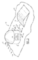
- the apparatus 30 includes a turret 12 that extends outwardly from the surface 14 and into an ambient flow.
- the surface 14 is the exterior surface of an aircraft fuselage.
- the turret 12 may be mounted upon and extend outwardly from other types of structures, including other types of air vehicles, other types of vehicles in general and other non-vehicular structures.
- the turret 12 may be mounted to structures internal to the surface 14 and projected through an opening in the surface 14 so that the aerodynamics of the aircraft is not effected by the presence of the turret 12 at all times, and so as to allow other functions of the aircraft to be performed without interference by the turret 12, including take-off and landing operations.
- the ambient flow may be a flow of a variety of different types of fluids.
- the ambient flow may move across the surface 14 in a predefined flow direction as a result of relative motion between the flow and the structure on which the turret 12 is mounted.
- the ambient flow is generally an air flow that passes over the surface 14 and around the turret as a result of the relative motion of the aircraft or other air vehicle through the air.
- the ambient flow propagates in a predefined flow direction relative to the surface 14 and the turret 12, such as shown by the rightwardly facing arrows 16 in Figure 2 .
- the turret 12 of the illustrated embodiment has a cylindrical portion 33 that is proximate to the surface 14 and a hemispherical portion 36 that defines a distal end of the turret.
- the turret 12 may be sized and shaped in a variety of different manners.
- the turret 12 may house portions of a variety of different systems. In one embodiment, however, the turret 12 houses at least a portion of a laser system, such as the at least some of the optical elements 38 for receiving and processing a laser beam, as schematically represented in dashed lines in Figure 2 .
- the apparatus 30 may also include a plurality of ejector nozzles 32 opening through the surface 14 and positioned proximate to and aft of the turret 12 relative to the ambient flow.
- the ejector nozzles 32 may create an ejector effect that reduces the pressure on the aft side of the turret 12 and reduces or eliminates flow separation by reducing or eliminating the adverse pressure gradient that otherwise is created aft of the turret.
- the ejector effect may cause the air surrounding the high velocity stream output by an ejector nozzle to be drawn into the stream by entrainment which results in the air being reduced in pressure and accelerated, such as to approximately Mach 1.
- the local pressure may then increase in the diffuser section downstream of the ejector nozzles 32.
- the apparatus 30 may include any number of ejector nozzles 32. Thus, while the illustrated embodiment of the apparatus 30 includes four ejector nozzles 32, the apparatus may include more or fewer ejector nozzles in other embodiments.
- an imaginary plane may be defined perpendicular to the surface 14 and through the turret with the imaginary plane separating the turret into that portion which faces the ambient flow and that portion that does not face the ambient flow and which is therefore considered aft of the turret.
- the imaginary plane may be defined so as to extend through the turret 12 along the dashed line 20 of Figure 1 that represents the line along the turret at which flow separation commences.
- some of the ejector nozzles 32 may be positioned to the side of the turret 12 relative to the predefined flow direction 16, but are still considered aft of the turret by being positioned downstream of the imaginary plane described above.
- the ejector nozzles 32 introduce a motive flow that accelerates a portion of the ambient flow that otherwise propagates proximate to the respective ejector nozzles, thereby lowering the pressure.
- the motive flow introduced by the ejector nozzles 32 has a greater velocity, typically a substantially greater velocity, than the ambient flow and, in one embodiment, is supersonic, while the ambient flow is transonic. This supersonic motive flow combines with the ambient flow proximate the ejector nozzles 32 and then undergoes one or more shocks as the combined flow passes through a subsonic diffuser region position aft of the turret so as to return to a subsonic flow condition.
- This transition to a subsonic flow condition causes the pressure of the combined flow to increase to that the flow may re-combine with the remainder of the ambient flow at the pressure of the ambient flow.
- the motive flow provided by the ejector nozzles 32 lowers the pressure and creates a partial vacuum aft of the turret 12 which draws a portion of the ambient flow into the region aft of the turret that otherwise may experience flow separation, thereby reducing or eliminating flow separation and the turbulence that may otherwise be created by such flow separation.
- the ejector nozzles 32 may be angled relative to the surface 14.
- the ejector nozzles 32 may be oriented relative to the surface 14 such that the motive flow introduced by the ejector nozzles propagates not only outwardly from the surface, but also in a downstream direction, that is, in the predefined flow direction 16, of the ambient flow.
- an ejector nozzle 32 may include a gas generator 34 for providing the motive flow at a temperature greater than an ambient temperature of the ambient flow.
- the motive flow may be comprised of a motive gas and a suction gas with the gas generator 34 of various embodiments providing different types of motive gas, including gas, air or steam produced by combustion or peroxide decomposition.
- the ejector nozzle 32 of the illustrated embodiment includes an inner nozzle 33 through which motive gas is introduced and a throat 35 surrounding the inner nozzle through which suction gas is introduced.
- the motive gas and the suction gas combine to create the motive flow that is provided by the respective ejector nozzle 32.
- the motive gas and the suction gas that are provided via the inner nozzle 33 and the throat 35, respectively, may be provided at different pressures and temperatures and may have different molecular weights. In one embodiment, these parameters may be defined, at least in part, by the conventional design curves for ejector nozzles shown in Figure 5 and described by DeFrate and Hoerl, Chem. Eng.
- the motive gas provided by the inner nozzle 33 of the ejector nozzle 32 may be designated "a"
- the suction gas provided by the throat 35 of the ejector nozzle may be designated "b”.
- a mixing section is positioned downstream of the ejector nozzle 32 followed by a diffuser section.
- the mixing section is generally proximate to and immediately aft of the turret 12, while the diffuser section is also aft of the turret, but is spaced from the turret in the downstream direction by the mixing section.
- the motive flow provided by the ejector nozzle 32 mixes with a portion of the ambient flow and then diffuses so as to return to the pressure of the ambient flow as the combined flow departs the diffuser section.
- the combination of the motive flow and a portion of the ambient flow that mixes with the motive flow may achieve supersonic velocities at a reduced pressure compared to the remainder of the ambient flow.
- the combined flow may proceed through a diffuser section which, in one embodiment, is configured such that the cross-sectional area for flow is reduced in a way that causes the flow velocity to be reduced to subsonic.
- the surface 14 of the aircraft may have a structural modifications, such as a ramp 39 as shown in Figure 2 , that reduce the area available for flow. These modifications may be oriented along the direction of the ambient flow, or may be oriented perpendicular to that direction.
- the end result of this diffuser section is to return the combined flow to a pressure at least as high as the ambient flow pressure. While this pressure relationship is necessary for ejector operation, a diffuser section is not necessarily required, but a diffuser section may be beneficial in some embodiments for reasons of efficiency in consumption of the media from which the motive flow is created.
- an aircraft upon which the apparatus 30 of one embodiment of the present disclosure is mounted may be designed for operating at an altitude at which the ambient pressure is 4 pounds per square inch absolute (psia), and the flow can be stabilized around the turret 12 such that flow separation is avoided at a suction pressure of 2 psia, which corresponds to the aircraft operating at a Mach number of approximately 0.7, that is, at a transonic speed.
- the suction pressure is the pressure of the suction gas provided by the throat.
- the determination of the motive flow may be determined based upon the design curves of Figure 5 .
- the intersection of the compression ratio p 3 /p b of 2 on the right side of the lower horizontal axis and the suction to motive ratio p b /p a of 0.02 on the vertical axis indicates an area ratio of about 80 on the right side of the upper horizontal axis, as indicated by the dashed lines that converge at point A in Figure 5 .
- an area ratio of about 80 indicates that the nozzle area, that is, the area of the openings of the ejector nozzles 32 in the aggregate is about 1/80 of the area of the ambient stream as defined by the total cross-sectional area of the turret 12 that is seen by the ambient stream.
- an entrainment ratio on the left side of the lower horizontal axis may be determined to be about 1.1 as indicated by the vertical dashed line B.
- the entrainment ratio indicates the quantity of fluid, such as air, that can be reduced in pressure to the pressure of the suction gas, that is, to the suction pressure, for every unit of motive gas that is provided.
- 1.1 kg of air may be reduced in pressure to 2 psia for every kilogram of steam provided as motive gas at 100 psia.
- a correction factor based upon temperature and molecular weight may also be utilized to more accurately define the entrainment ratio.
- the correction factor may be determined as (T a M b /T b M a ) 1/2 where T and M are the temperature and the molecular weight of the motive gas (designated by subscript a) and the suction gas (designated by subscript b). In one embodiment in which T a and T b are 500K and 200K, respectively, and M a and M b are 18 and 29, respectively, the correction factor is about 2.
- the entrainment ratio may be multiplied by the correction factor to determine the quantity of fluid, such as air, that can be reduced in pressure to the pressure of the suction gas, that is, to the suction pressure, per unit of motive gas.
- the entrainment ratio is 1.1 and the correction factor is 2, 2.2 kg of air may be evacuated per kilogram of steam.
- ambient flow for a turret 12 having a frontal area of about 0.5 meters x 0.5 meters at a Mach number of 0.7 is about 10 kg/sec.
- the gas generator 34 will be required to produce about 4.5 kg/s (10 kg/sec / 2.2) of motive gas, a quantity that may be readily produced.
- the ejector nozzles 32 may have various sizes depending upon the application, but, in one embodiment, the apparatus 30 may include a relatively large number of ejector nozzles, with each ejector nozzle being relatively small.
- the motive flow provided by an ejector nozzle 32 typically requires a flow length in the predefined flow direction equal to about ten times the diameter of the ejector nozzle at its opening through the surface 14 to recover to subsonic conditions.
- the motive flow provided by the ejector nozzles 32 mix with a portion of the ambient flow in a mixing region aft of the turret 12.
- other portions of the ambient flow may pour into the mixing regions from outboard of the turret area.
- the apparatus 30 may therefore also include one or more of a flow splitter, a shield and/or other barrier 37 aft of the turret 12 that serves to provide some degree of isolation to the region on the aft side of the turret and to limit the inflow of other portions of the ambient flow from regions outboard of the turret into the mixing region of reduced pressure.
- the flow rate requirements may be reduced which, in turn, may permit the size of the ejector nozzles 32 to be reduced, thereby requiring less space for recovery to subsonic conditions.
- embodiments of the present disclosure may introduce a motive flow aft of the turret that has a greater velocity than the ambient flow. See operations 40 and 42.
- This motive flow may create a region of reduced pressure aft of a turret 12 so as to prevent or reduce flow separation and the concomitant turbulence which may effect performance of the system housed by the turret, such as by altering laser beam propagation therethrough. See operation 44 of Figure 7 .
- the pressure of the gas flowing through the reduced pressure region may be restored to at least as high of a pressure as the ambient pressure of the ambient flow to ensure that the flow is stable and continues along the surface 14. See operation 46 of Figure 7 .
- the region of reduced pressure may be created by an ejector nozzle 32 having a gas generator 34 for providing a motive flow at an elevated temperature that creates a supersonic flow.
- the supersonic flow generated by the ejector nozzle 32 and the subsonic flow of a portion of the ambient flow about the turret 12 may merge so as to flow along the surface 14.
- the apparatus 30 of embodiments of the present disclosure are particularly useful in conjunction with transonic ambient flows as noted above.
Landscapes
- Engineering & Computer Science (AREA)
- Aviation & Aerospace Engineering (AREA)
- Physics & Mathematics (AREA)
- Fluid Mechanics (AREA)
- Mechanical Engineering (AREA)
- General Engineering & Computer Science (AREA)
- Jet Pumps And Other Pumps (AREA)
Claims (10)
- Dispositif (30) destiné à contrôler le flux comprenant :une surface (14) et une tourelle (12) s'étendant à l'extérieur de la surface et dans un flux ambiant qui se propage dans une direction de flux prédéfinie par rapport à la surface et à la tourelle ; etune pluralité de buses d'éjection (32) s'ouvrant au travers de la surface et positionnées à proximité et à l'arrière de la tourelle par rapport au flux ambiant, dans lequel la pluralité de buses d'éjection est configurée pour introduire un flux moteur dont la vitesse est supérieure à celle du flux ambiant pour créer par là-même à l'arrière de la tourelle une région de pression réduite par rapport à une pression ambiante, dans laquelle une partie du flux ambiant se mélange avec le flux moteur.
- Dispositif (30) selon la revendication 1, dans lequel chaque buse d'éjection (32) comprend une buse intérieure (33), par laquelle du gaz moteur est introduit et un étranglement (35) entourant la buse intérieure, par lequel du gaz d'aspiration est introduit à une pression différente que celle du gaz moteur de sorte que le gaz moteur et le gaz d'aspiration se combinent pour créer le flux moteur.
- Dispositif (30) selon la revendication 2, dans lequel chaque buse d'éjection (32) comprend un générateur de gaz (34) pour fournir du gaz moteur à une température supérieure à une température ambiante du flux ambiant.
- Dispositif (30) selon la revendication 1, dans lequel le flux ambiant est transsonique et dans lequel la pluralité de buses d'éjection (32) est configurée pour introduire le flux moteur à une vitesse supersonique.
- Dispositif (30) selon la revendication 1, comprenant en outre un redirecteur de flux (39) positionné à l'arrière de la tourelle (12) et s'étendant à l'extérieur de la surface (14).
- Dispositif (30) selon la revendication 5, dans lequel le redirecteur de flux comprend une rampe.
- Procédé de commande du flux comprenant :l'établissement d'un flux ambiant qui se propage dans une direction de flux prédéfinie autour d'une tourelle (12) qui s'étend à l'extérieur d'une surface (14) et dans le flux ambiant ; etl'introduction d'un flux moteur provenant d'une pluralité de buses d'éjection (32) qui s'ouvrent au travers de la surface et sont positionnées à proximité et à l'arrière de la tourelle par rapport au flux ambiant, dans lequel le flux moteur présente une vitesse supérieure à celle du flux ambiant pour créer par là-même à l'arrière de la tourelle une région de pression réduite par rapport à une pression ambiante, dans laquelle une partie du flux ambiant se mélange avec le flux moteur.
- Procédé selon la revendication 7, dans lequel l'introduction du flux moteur comprend l'introduction d'un gaz moteur par une buse intérieure (33) de chaque buse d'éjection (32) et l'introduction d'un gaz d'aspiration par un étranglement (35) de chaque buse d'éjection qui entoure la buse intérieure respective et dans lequel le gaz d'aspiration est introduit à une pression différente de celle du gaz moteur de sorte que le gaz moteur et le gaz d'aspiration se combinent pour créer un flux moteur.
- Procédé selon la revendication 7, dans lequel l'établissement du flux ambiant comprend l'établissement transsonique du flux ambiant et dans lequel l'introduction du flux moteur comprend l'introduction du flux moteur à une vitesse supersonique.
- Procédé selon la revendication 7, comprenant en outre le logement d'un ou plusieurs composants d'un système laser dans la tourelle (12).
Applications Claiming Priority (2)
| Application Number | Priority Date | Filing Date | Title |
|---|---|---|---|
| US12/842,534 US8870122B2 (en) | 2010-07-23 | 2010-07-23 | Method and apparatus for controlling flow about a turret |
| PCT/US2011/040151 WO2012012036A1 (fr) | 2010-07-23 | 2011-06-13 | Procédé et appareil de maîtrise de l'écoulement autour d'une tourelle |
Publications (2)
| Publication Number | Publication Date |
|---|---|
| EP2595880A1 EP2595880A1 (fr) | 2013-05-29 |
| EP2595880B1 true EP2595880B1 (fr) | 2014-05-14 |
Family
ID=44627509
Family Applications (1)
| Application Number | Title | Priority Date | Filing Date |
|---|---|---|---|
| EP20110727877 Not-in-force EP2595880B1 (fr) | 2010-07-23 | 2011-06-13 | Procédé et appareil de maîtrise de l'écoulement autour d'une tourelle |
Country Status (3)
| Country | Link |
|---|---|
| US (1) | US8870122B2 (fr) |
| EP (1) | EP2595880B1 (fr) |
| WO (1) | WO2012012036A1 (fr) |
Cited By (1)
| Publication number | Priority date | Publication date | Assignee | Title |
|---|---|---|---|---|
| EP3732101A1 (fr) * | 2017-12-28 | 2020-11-04 | Aero Design Labs, Inc. | Appareil de réduction de traînée d'un écoulement de sortie de conduit transversal |
Families Citing this family (4)
| Publication number | Priority date | Publication date | Assignee | Title |
|---|---|---|---|---|
| US9567056B2 (en) * | 2014-03-06 | 2017-02-14 | General Atomics Aeronautical Systems, Inc. | Devices, systems and methods for passive control of flow |
| US10232929B2 (en) | 2015-12-18 | 2019-03-19 | Sikorsky Aircraft Corporation | Plate member for reducing drag on a fairing of an aircraft |
| US10220939B2 (en) * | 2015-12-18 | 2019-03-05 | Sikorsky Aircraft Corporation | Active airflow system and method of reducing drag for aircraft |
| US10174772B2 (en) * | 2016-12-16 | 2019-01-08 | Raytheon Company | Device and method for controlling fluid flow over an optical instrument |
Family Cites Families (21)
| Publication number | Priority date | Publication date | Assignee | Title |
|---|---|---|---|---|
| US2500712A (en) * | 1945-06-07 | 1950-03-14 | Serrell Jesse Pound | Multiple combustion unit pulse jet engine |
| GB703149A (en) | 1950-04-13 | 1954-01-27 | Blackburn & Gen Aircraft Ltd | Improvements in or relating to radomes of aircraft |
| US2951662A (en) * | 1958-04-21 | 1960-09-06 | Republic Aviat Corp | Boundary layer control means for obtaining high lift for aircraft |
| US2973922A (en) * | 1959-04-10 | 1961-03-07 | Power Jets Res & Dev Ltd | Jet propelled aircraft |
| US3085740A (en) * | 1960-08-30 | 1963-04-16 | Ryan Aeronautical Co | End inlet jet pump for boundary layer control system |
| US3441236A (en) * | 1967-01-16 | 1969-04-29 | Eric Arnholdt | Airfoil |
| US5806789A (en) | 1995-08-22 | 1998-09-15 | Lockheed Corporation | Optical apparatus for an aircraft |
| US5775643A (en) * | 1996-10-18 | 1998-07-07 | The Boeing Company | Passive flow control aero-optical turret assembly |
| WO1999044887A1 (fr) * | 1998-03-06 | 1999-09-10 | Batcho Paul F | Procede et appareil d'attenuation des ecoulements aux jonctions |
| US6105904A (en) * | 1998-03-30 | 2000-08-22 | Orbital Research Inc. | Deployable flow control device |
| FR2783497B1 (fr) | 1998-09-22 | 2000-12-08 | Gerard Fournier | Avion a aile supercritique a faible trainee d'onde |
| EP2090769A1 (fr) * | 2000-10-02 | 2009-08-19 | Rohr, Inc. | Appareil, procédé et système de réduction sonore de moteur à turbine à gaz |
| WO2002038442A2 (fr) * | 2000-10-10 | 2002-05-16 | The Regents Of The University Of California | Volets translationnels microfabriques permettant de reguler la charge aerodynamique |
| US6409126B1 (en) * | 2000-11-01 | 2002-06-25 | Lockhead Martin Corporation | Passive flow control of bluff body wake turbulence |
| US20020134891A1 (en) * | 2001-02-09 | 2002-09-26 | Guillot Stephen A. | Ejector pump flow control |
| US6758032B2 (en) | 2002-02-07 | 2004-07-06 | Lockheed Martin Corporation | System of pulsed detonation injection for fluid flow control of inlets, nozzles, and lift fans |
| DE102004024007B4 (de) * | 2004-05-13 | 2007-10-11 | Airbus Deutschland Gmbh | Flugzeugkomponente, insbesondere Flügel |
| US7823839B2 (en) * | 2005-10-31 | 2010-11-02 | Georgia Tech Research Corporation | Airfoil performance modification using synthetic jet actuators |
| US7815150B2 (en) * | 2007-08-20 | 2010-10-19 | The Boeing Company | Beam director flow control |
| US9126697B2 (en) * | 2008-09-29 | 2015-09-08 | The Boeing Company | Atmospheric turbulence isolation system and method |
| US8232706B2 (en) | 2009-01-09 | 2012-07-31 | The Boeing Company | Autonomous power generation unit for auxiliary system on an airborne platform |
-
2010
- 2010-07-23 US US12/842,534 patent/US8870122B2/en not_active Expired - Fee Related
-
2011
- 2011-06-13 EP EP20110727877 patent/EP2595880B1/fr not_active Not-in-force
- 2011-06-13 WO PCT/US2011/040151 patent/WO2012012036A1/fr not_active Ceased
Cited By (1)
| Publication number | Priority date | Publication date | Assignee | Title |
|---|---|---|---|---|
| EP3732101A1 (fr) * | 2017-12-28 | 2020-11-04 | Aero Design Labs, Inc. | Appareil de réduction de traînée d'un écoulement de sortie de conduit transversal |
Also Published As
| Publication number | Publication date |
|---|---|
| WO2012012036A1 (fr) | 2012-01-26 |
| EP2595880A1 (fr) | 2013-05-29 |
| US20120018004A1 (en) | 2012-01-26 |
| US8870122B2 (en) | 2014-10-28 |
Similar Documents
| Publication | Publication Date | Title |
|---|---|---|
| EP2215341B1 (fr) | Tuyère pour un système de propulsion à faibles ondes de chocs et méthode | |
| US4824048A (en) | Induction lift flying saucer | |
| US20200284219A1 (en) | Generation of a Pulsed Jet by Jet Vectoring Through a Nozzle with Multiple Outlets | |
| US8038102B2 (en) | System and method to control flowfield vortices with micro-jet arrays | |
| US10967980B2 (en) | Turbine engine propelled airplane having an acoustic baffle | |
| EP1710156B1 (fr) | Avion avec système de contrôle de fluide autour de la tuyère du moteur et procédé | |
| EP2595880B1 (fr) | Procédé et appareil de maîtrise de l'écoulement autour d'une tourelle | |
| CN108137149A (zh) | 喷射器和翼型构型 | |
| EP3112650B1 (fr) | Limiteur d'écoulement d'entrée | |
| US20040011917A1 (en) | Shock wave modification via shock induced ion doping | |
| CA2802426A1 (fr) | Aeronef motorise, en particulier aeronef realise sous forme d'aile volante et/ou avec une faible signature radar | |
| US20160152324A1 (en) | Fluidic fence for performance enhancement | |
| Martens et al. | Jet noise reduction for high speed exhaust systems | |
| Laruelle et al. | Air Intakes: role, constraints and design | |
| Jain et al. | Study on fluidic thrust vectoring techniques for application in V/STOL aircrafts | |
| US4651953A (en) | Induction lift aircraft | |
| RU2094307C1 (ru) | Транспортный самолет с затупленной хвостовой частью фюзеляжа | |
| Burrows et al. | Controlled flow dynamics in a serpentine diffuser with a cowl inlet | |
| EP3638587B1 (fr) | Configurations d'éjecteur à ailettes | |
| Takahashi | Performance Evaluation of Turbine-Based Combination Cycle Propulsion Systems with Advanced Nozzle Integration | |
| Dhamanekar et al. | Feasibility study of engine bay ventilation with intake air driven by ejector nozzle |
Legal Events
| Date | Code | Title | Description |
|---|---|---|---|
| PUAI | Public reference made under article 153(3) epc to a published international application that has entered the european phase |
Free format text: ORIGINAL CODE: 0009012 |
|
| 17P | Request for examination filed |
Effective date: 20130219 |
|
| AK | Designated contracting states |
Kind code of ref document: A1 Designated state(s): AL AT BE BG CH CY CZ DE DK EE ES FI FR GB GR HR HU IE IS IT LI LT LU LV MC MK MT NL NO PL PT RO RS SE SI SK SM TR |
|
| DAX | Request for extension of the european patent (deleted) | ||
| RIC1 | Information provided on ipc code assigned before grant |
Ipc: B64D 47/08 20060101ALI20131029BHEP Ipc: B64D 7/00 20060101ALI20131029BHEP Ipc: F15D 1/00 20060101ALI20131029BHEP Ipc: B64C 23/04 20060101ALI20131029BHEP Ipc: B64C 7/00 20060101AFI20131029BHEP Ipc: B64C 21/04 20060101ALI20131029BHEP |
|
| GRAP | Despatch of communication of intention to grant a patent |
Free format text: ORIGINAL CODE: EPIDOSNIGR1 |
|
| INTG | Intention to grant announced |
Effective date: 20131209 |
|
| GRAS | Grant fee paid |
Free format text: ORIGINAL CODE: EPIDOSNIGR3 |
|
| GRAA | (expected) grant |
Free format text: ORIGINAL CODE: 0009210 |
|
| AK | Designated contracting states |
Kind code of ref document: B1 Designated state(s): AL AT BE BG CH CY CZ DE DK EE ES FI FR GB GR HR HU IE IS IT LI LT LU LV MC MK MT NL NO PL PT RO RS SE SI SK SM TR |
|
| REG | Reference to a national code |
Ref country code: GB Ref legal event code: FG4D |
|
| REG | Reference to a national code |
Ref country code: AT Ref legal event code: REF Ref document number: 668078 Country of ref document: AT Kind code of ref document: T Effective date: 20140615 |
|
| REG | Reference to a national code |
Ref country code: IE Ref legal event code: FG4D |
|
| REG | Reference to a national code |
Ref country code: DE Ref legal event code: R096 Ref document number: 602011006992 Country of ref document: DE Effective date: 20140703 |
|
| REG | Reference to a national code |
Ref country code: NL Ref legal event code: VDEP Effective date: 20140514 Ref country code: AT Ref legal event code: MK05 Ref document number: 668078 Country of ref document: AT Kind code of ref document: T Effective date: 20140514 |
|
| REG | Reference to a national code |
Ref country code: LT Ref legal event code: MG4D |
|
| PG25 | Lapsed in a contracting state [announced via postgrant information from national office to epo] |
Ref country code: CY Free format text: LAPSE BECAUSE OF FAILURE TO SUBMIT A TRANSLATION OF THE DESCRIPTION OR TO PAY THE FEE WITHIN THE PRESCRIBED TIME-LIMIT Effective date: 20140514 Ref country code: IS Free format text: LAPSE BECAUSE OF FAILURE TO SUBMIT A TRANSLATION OF THE DESCRIPTION OR TO PAY THE FEE WITHIN THE PRESCRIBED TIME-LIMIT Effective date: 20140914 Ref country code: FI Free format text: LAPSE BECAUSE OF FAILURE TO SUBMIT A TRANSLATION OF THE DESCRIPTION OR TO PAY THE FEE WITHIN THE PRESCRIBED TIME-LIMIT Effective date: 20140514 Ref country code: GR Free format text: LAPSE BECAUSE OF FAILURE TO SUBMIT A TRANSLATION OF THE DESCRIPTION OR TO PAY THE FEE WITHIN THE PRESCRIBED TIME-LIMIT Effective date: 20140815 Ref country code: LT Free format text: LAPSE BECAUSE OF FAILURE TO SUBMIT A TRANSLATION OF THE DESCRIPTION OR TO PAY THE FEE WITHIN THE PRESCRIBED TIME-LIMIT Effective date: 20140514 Ref country code: NO Free format text: LAPSE BECAUSE OF FAILURE TO SUBMIT A TRANSLATION OF THE DESCRIPTION OR TO PAY THE FEE WITHIN THE PRESCRIBED TIME-LIMIT Effective date: 20140814 |
|
| PG25 | Lapsed in a contracting state [announced via postgrant information from national office to epo] |
Ref country code: HR Free format text: LAPSE BECAUSE OF FAILURE TO SUBMIT A TRANSLATION OF THE DESCRIPTION OR TO PAY THE FEE WITHIN THE PRESCRIBED TIME-LIMIT Effective date: 20140514 Ref country code: LV Free format text: LAPSE BECAUSE OF FAILURE TO SUBMIT A TRANSLATION OF THE DESCRIPTION OR TO PAY THE FEE WITHIN THE PRESCRIBED TIME-LIMIT Effective date: 20140514 Ref country code: ES Free format text: LAPSE BECAUSE OF FAILURE TO SUBMIT A TRANSLATION OF THE DESCRIPTION OR TO PAY THE FEE WITHIN THE PRESCRIBED TIME-LIMIT Effective date: 20140514 Ref country code: AT Free format text: LAPSE BECAUSE OF FAILURE TO SUBMIT A TRANSLATION OF THE DESCRIPTION OR TO PAY THE FEE WITHIN THE PRESCRIBED TIME-LIMIT Effective date: 20140514 Ref country code: SE Free format text: LAPSE BECAUSE OF FAILURE TO SUBMIT A TRANSLATION OF THE DESCRIPTION OR TO PAY THE FEE WITHIN THE PRESCRIBED TIME-LIMIT Effective date: 20140514 Ref country code: PL Free format text: LAPSE BECAUSE OF FAILURE TO SUBMIT A TRANSLATION OF THE DESCRIPTION OR TO PAY THE FEE WITHIN THE PRESCRIBED TIME-LIMIT Effective date: 20140514 Ref country code: RS Free format text: LAPSE BECAUSE OF FAILURE TO SUBMIT A TRANSLATION OF THE DESCRIPTION OR TO PAY THE FEE WITHIN THE PRESCRIBED TIME-LIMIT Effective date: 20140514 |
|
| PG25 | Lapsed in a contracting state [announced via postgrant information from national office to epo] |
Ref country code: PT Free format text: LAPSE BECAUSE OF FAILURE TO SUBMIT A TRANSLATION OF THE DESCRIPTION OR TO PAY THE FEE WITHIN THE PRESCRIBED TIME-LIMIT Effective date: 20140915 |
|
| PG25 | Lapsed in a contracting state [announced via postgrant information from national office to epo] |
Ref country code: EE Free format text: LAPSE BECAUSE OF FAILURE TO SUBMIT A TRANSLATION OF THE DESCRIPTION OR TO PAY THE FEE WITHIN THE PRESCRIBED TIME-LIMIT Effective date: 20140514 Ref country code: CZ Free format text: LAPSE BECAUSE OF FAILURE TO SUBMIT A TRANSLATION OF THE DESCRIPTION OR TO PAY THE FEE WITHIN THE PRESCRIBED TIME-LIMIT Effective date: 20140514 Ref country code: RO Free format text: LAPSE BECAUSE OF FAILURE TO SUBMIT A TRANSLATION OF THE DESCRIPTION OR TO PAY THE FEE WITHIN THE PRESCRIBED TIME-LIMIT Effective date: 20140514 Ref country code: DK Free format text: LAPSE BECAUSE OF FAILURE TO SUBMIT A TRANSLATION OF THE DESCRIPTION OR TO PAY THE FEE WITHIN THE PRESCRIBED TIME-LIMIT Effective date: 20140514 Ref country code: BE Free format text: LAPSE BECAUSE OF FAILURE TO SUBMIT A TRANSLATION OF THE DESCRIPTION OR TO PAY THE FEE WITHIN THE PRESCRIBED TIME-LIMIT Effective date: 20140514 Ref country code: SK Free format text: LAPSE BECAUSE OF FAILURE TO SUBMIT A TRANSLATION OF THE DESCRIPTION OR TO PAY THE FEE WITHIN THE PRESCRIBED TIME-LIMIT Effective date: 20140514 |
|
| REG | Reference to a national code |
Ref country code: CH Ref legal event code: PL |
|
| REG | Reference to a national code |
Ref country code: DE Ref legal event code: R097 Ref document number: 602011006992 Country of ref document: DE |
|
| PG25 | Lapsed in a contracting state [announced via postgrant information from national office to epo] |
Ref country code: NL Free format text: LAPSE BECAUSE OF FAILURE TO SUBMIT A TRANSLATION OF THE DESCRIPTION OR TO PAY THE FEE WITHIN THE PRESCRIBED TIME-LIMIT Effective date: 20140514 |
|
| PLBE | No opposition filed within time limit |
Free format text: ORIGINAL CODE: 0009261 |
|
| STAA | Information on the status of an ep patent application or granted ep patent |
Free format text: STATUS: NO OPPOSITION FILED WITHIN TIME LIMIT |
|
| REG | Reference to a national code |
Ref country code: IE Ref legal event code: MM4A |
|
| 26N | No opposition filed |
Effective date: 20150217 |
|
| PG25 | Lapsed in a contracting state [announced via postgrant information from national office to epo] |
Ref country code: IT Free format text: LAPSE BECAUSE OF FAILURE TO SUBMIT A TRANSLATION OF THE DESCRIPTION OR TO PAY THE FEE WITHIN THE PRESCRIBED TIME-LIMIT Effective date: 20140514 Ref country code: IE Free format text: LAPSE BECAUSE OF NON-PAYMENT OF DUE FEES Effective date: 20140613 Ref country code: CH Free format text: LAPSE BECAUSE OF NON-PAYMENT OF DUE FEES Effective date: 20140630 Ref country code: LI Free format text: LAPSE BECAUSE OF NON-PAYMENT OF DUE FEES Effective date: 20140630 |
|
| REG | Reference to a national code |
Ref country code: DE Ref legal event code: R097 Ref document number: 602011006992 Country of ref document: DE Effective date: 20150217 |
|
| PG25 | Lapsed in a contracting state [announced via postgrant information from national office to epo] |
Ref country code: SI Free format text: LAPSE BECAUSE OF FAILURE TO SUBMIT A TRANSLATION OF THE DESCRIPTION OR TO PAY THE FEE WITHIN THE PRESCRIBED TIME-LIMIT Effective date: 20140514 |
|
| PG25 | Lapsed in a contracting state [announced via postgrant information from national office to epo] |
Ref country code: MT Free format text: LAPSE BECAUSE OF FAILURE TO SUBMIT A TRANSLATION OF THE DESCRIPTION OR TO PAY THE FEE WITHIN THE PRESCRIBED TIME-LIMIT Effective date: 20140514 |
|
| PG25 | Lapsed in a contracting state [announced via postgrant information from national office to epo] |
Ref country code: SM Free format text: LAPSE BECAUSE OF FAILURE TO SUBMIT A TRANSLATION OF THE DESCRIPTION OR TO PAY THE FEE WITHIN THE PRESCRIBED TIME-LIMIT Effective date: 20140514 Ref country code: MC Free format text: LAPSE BECAUSE OF FAILURE TO SUBMIT A TRANSLATION OF THE DESCRIPTION OR TO PAY THE FEE WITHIN THE PRESCRIBED TIME-LIMIT Effective date: 20140514 |
|
| REG | Reference to a national code |
Ref country code: FR Ref legal event code: PLFP Year of fee payment: 6 |
|
| PG25 | Lapsed in a contracting state [announced via postgrant information from national office to epo] |
Ref country code: BG Free format text: LAPSE BECAUSE OF FAILURE TO SUBMIT A TRANSLATION OF THE DESCRIPTION OR TO PAY THE FEE WITHIN THE PRESCRIBED TIME-LIMIT Effective date: 20140514 |
|
| PG25 | Lapsed in a contracting state [announced via postgrant information from national office to epo] |
Ref country code: TR Free format text: LAPSE BECAUSE OF FAILURE TO SUBMIT A TRANSLATION OF THE DESCRIPTION OR TO PAY THE FEE WITHIN THE PRESCRIBED TIME-LIMIT Effective date: 20140514 Ref country code: HU Free format text: LAPSE BECAUSE OF FAILURE TO SUBMIT A TRANSLATION OF THE DESCRIPTION OR TO PAY THE FEE WITHIN THE PRESCRIBED TIME-LIMIT; INVALID AB INITIO Effective date: 20110613 Ref country code: LU Free format text: LAPSE BECAUSE OF NON-PAYMENT OF DUE FEES Effective date: 20140613 |
|
| REG | Reference to a national code |
Ref country code: FR Ref legal event code: PLFP Year of fee payment: 7 |
|
| REG | Reference to a national code |
Ref country code: FR Ref legal event code: PLFP Year of fee payment: 8 |
|
| PG25 | Lapsed in a contracting state [announced via postgrant information from national office to epo] |
Ref country code: MK Free format text: LAPSE BECAUSE OF FAILURE TO SUBMIT A TRANSLATION OF THE DESCRIPTION OR TO PAY THE FEE WITHIN THE PRESCRIBED TIME-LIMIT Effective date: 20140514 |
|
| PG25 | Lapsed in a contracting state [announced via postgrant information from national office to epo] |
Ref country code: AL Free format text: LAPSE BECAUSE OF FAILURE TO SUBMIT A TRANSLATION OF THE DESCRIPTION OR TO PAY THE FEE WITHIN THE PRESCRIBED TIME-LIMIT Effective date: 20140514 |
|
| REG | Reference to a national code |
Ref country code: DE Ref legal event code: R082 Ref document number: 602011006992 Country of ref document: DE Representative=s name: KILBURN & STRODE LLP, NL |
|
| PGFP | Annual fee paid to national office [announced via postgrant information from national office to epo] |
Ref country code: FR Payment date: 20210625 Year of fee payment: 11 Ref country code: DE Payment date: 20210629 Year of fee payment: 11 |
|
| PGFP | Annual fee paid to national office [announced via postgrant information from national office to epo] |
Ref country code: GB Payment date: 20210628 Year of fee payment: 11 |
|
| REG | Reference to a national code |
Ref country code: DE Ref legal event code: R119 Ref document number: 602011006992 Country of ref document: DE |
|
| GBPC | Gb: european patent ceased through non-payment of renewal fee |
Effective date: 20220613 |
|
| PG25 | Lapsed in a contracting state [announced via postgrant information from national office to epo] |
Ref country code: FR Free format text: LAPSE BECAUSE OF NON-PAYMENT OF DUE FEES Effective date: 20220630 |
|
| PG25 | Lapsed in a contracting state [announced via postgrant information from national office to epo] |
Ref country code: GB Free format text: LAPSE BECAUSE OF NON-PAYMENT OF DUE FEES Effective date: 20220613 Ref country code: DE Free format text: LAPSE BECAUSE OF NON-PAYMENT OF DUE FEES Effective date: 20230103 |