EP2596175B1 - Wellenenergiegewinnungsvorrichtung zur energieproduktion anhand von hydraulischen turbinen und stromgeneratoren - Google Patents
Wellenenergiegewinnungsvorrichtung zur energieproduktion anhand von hydraulischen turbinen und stromgeneratoren Download PDFInfo
- Publication number
- EP2596175B1 EP2596175B1 EP11749916.0A EP11749916A EP2596175B1 EP 2596175 B1 EP2596175 B1 EP 2596175B1 EP 11749916 A EP11749916 A EP 11749916A EP 2596175 B1 EP2596175 B1 EP 2596175B1
- Authority
- EP
- European Patent Office
- Prior art keywords
- tank
- waves
- water
- sea
- wall
- Prior art date
- Legal status (The legal status is an assumption and is not a legal conclusion. Google has not performed a legal analysis and makes no representation as to the accuracy of the status listed.)
- Active
Links
Images

Classifications
-
- E—FIXED CONSTRUCTIONS
- E02—HYDRAULIC ENGINEERING; FOUNDATIONS; SOIL SHIFTING
- E02B—HYDRAULIC ENGINEERING
- E02B9/00—Water-power plants; Layout, construction or equipment, methods of, or apparatus for, making same
- E02B9/08—Tide or wave power plants
-
- Y—GENERAL TAGGING OF NEW TECHNOLOGICAL DEVELOPMENTS; GENERAL TAGGING OF CROSS-SECTIONAL TECHNOLOGIES SPANNING OVER SEVERAL SECTIONS OF THE IPC; TECHNICAL SUBJECTS COVERED BY FORMER USPC CROSS-REFERENCE ART COLLECTIONS [XRACs] AND DIGESTS
- Y02—TECHNOLOGIES OR APPLICATIONS FOR MITIGATION OR ADAPTATION AGAINST CLIMATE CHANGE
- Y02E—REDUCTION OF GREENHOUSE GAS [GHG] EMISSIONS, RELATED TO ENERGY GENERATION, TRANSMISSION OR DISTRIBUTION
- Y02E10/00—Energy generation through renewable energy sources
- Y02E10/30—Energy from the sea, e.g. using wave energy or salinity gradient
-
- Y—GENERAL TAGGING OF NEW TECHNOLOGICAL DEVELOPMENTS; GENERAL TAGGING OF CROSS-SECTIONAL TECHNOLOGIES SPANNING OVER SEVERAL SECTIONS OF THE IPC; TECHNICAL SUBJECTS COVERED BY FORMER USPC CROSS-REFERENCE ART COLLECTIONS [XRACs] AND DIGESTS
- Y02—TECHNOLOGIES OR APPLICATIONS FOR MITIGATION OR ADAPTATION AGAINST CLIMATE CHANGE
- Y02P—CLIMATE CHANGE MITIGATION TECHNOLOGIES IN THE PRODUCTION OR PROCESSING OF GOODS
- Y02P70/00—Climate change mitigation technologies in the production process for final industrial or consumer products
- Y02P70/50—Manufacturing or production processes characterised by the final manufactured product
Definitions
- the present invention pertains to the field of the exploitation of renewable and sustainable energy of the sea waves, even of low ones; the aim of the present invention is to produce electric energy with features such that the inlet in a transmission electrical power network is allowed, although the main source generating it is highly irregular.
- the electric energy produced by means of the inventive object can be used for supplying accumulation forms of energy, such for example the hydrogen production, by means of water electrolysis or other process known at the state of the art.
- the document US 1868087 describes a system for capturing the energy of sea waves, where it is provided a turbine positioned on the average calm sea level.
- the document DE3029087 describes a hydroelectric system comprising a barrier positioned on the average sea level allowing the accumulation of water so that it results a reduced hydraulic gap.
- the system comprises some canalizations and a turbo-generator unit which exploits such hydraulic gap.
- an apparatus for generating energy from the sea waves comprising: at least a tank provided of a wall with openings provided with means able to capture the water of the waves breaking thereon, thus allowing its inlet and avoiding its outlet so that the free level of water accumulated in the tank is at an height higher than the one of the calm sea; at least a communication duct between the tank and the sea, passing across the tank wall opposed to the one equipped for capturing the waves, configured in such a way that the water accumulated in said tank is discharged in a sea section not exposed to the direct action of the waves.
- Aim of the present invention is therefore to provide an apparatus for capturing the energy contained in the sea waves, which is particularly efficient for exploiting the irregular and low waves as well.
- the apparatus object of the present invention comprises at least a tank (1) able to capture the water of the sea waves.
- a tank can be positioned close to and on the outer side of tidal barriers (D) or breakwater barriers (C).
- the tanks (1) can be positioned directly near the barrier (D) or breakwater barrier (C), as it is shown in figures 1 and 2 , or at a certain distance, in parallel to the same barrier or the breakwater barrier.
- the tidal barriers (D) are those marine structures realized for the protection of harbours; they are structures in concrete and separate the calm sea (side B), as it is protected by the same barrier, from the open sea (side A) which, in favourable conditions, can be rough sea.
- the breakwater barriers (C) are those marine structures realized with an assembly of rocks arranged in parallel to the shore, functioning as protection of the littoral from the erosion of the surges, separating the calm sea (side B) as it is protected by the same barrier from the open sea (side A).
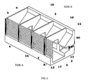
- the tanks can be also arranged isolated, in parallel and at a suitable distance from the coast for the protection of the littoral from the erosion of surges, thus being also able to function as protection of the coast, which is generally peculiar to the tidal barriers or the breakwater barriers, as it is shown in figure 3 .
- the tanks With the tanks in isolated position, it is provided a separation between the calm sea (side B), as it is protected by the same tank, and the open sea (side A) .
- the tank (1) comprised in the apparatus according to the present invention is always in an interposed position between two opposed sea sections, the one (side A) characterized by the presence of waves coming from the open sea, the other (side B) by the absence of waves as it is positioned on the side protected by the same tank (1) or by the tidal barrier (D) or by the breakwater barrier (C).
- the side A towards the open sea of the tanks is mainly parallel to the wave front.
- the side B, opposed to the side A faces a surface of calm sea as it is protected by the same marine structure.
- the wall of the tank (1) facing the side A is equipped to allow to capture the water of the waves breaking thereon allowing the inlet in the tank of the water transported thereby and avoiding its outlet. Due to this functioning mode, the tank supply is episodic and inconstant, and occurs in concomitance with the wave breaking. With regards to the tank positioning, the wave breaking occurs as the same time along the whole wall interested by the wave front.
- the water captured in the tanks accumulates with its potential energy at an height (H) higher than the free "calm sea” level arranged on the side B.
- the potential energy contained in the water accumulation thus created can be so exploited to produce electric energy by actuating hydraulic turbines (2), which are coupled to current generators (3), and put in motion by the transfer of water accumulated by the accumulation tank (1) in the surface of calm sea arranged on the side B.
- the tank (1) is supplied by filling itself when the wave comes, to tend then to empty itself before the next wave arrives.
- the hydraulic head is continually variable and so it is equally variable the water flow crossing the turbines and as a consequence also the characteristic parameters of the electric energy produced notwithstanding the presence of suitable flywheels change.
- the electric energy produced can be input in the net only upon stabilization or used to produce hydrogen.
- each tank (1) it can be conveniently provided a proper number of discharge ducts (13), in each of which being installed a turbine (3) so that it is possible to adjust, in certain limits, the flow rate supplying each turbine (3) bu opening and closing a portion of the discharge ducts (13) according to the inlet flow rate in the tank (1) which in turn depends on the height of the waves.
- the number of the active discharge ducts is to selected such that the tank is allowed to be almost completely emptied between a wave and the other one.
- the number of functioning turbines is then related to the sea condition.
- the tanks (1) can be ballasted, variable in width in proportion to the height and in particular can be divergent upwards, as it is shown in the section views of figures 1 and 2 and 3 .
- the tanks can be long between 4.00 and 8.00 m at the average level of the free "calm sea” in low tide condition (indicated by the symbol 00 in figures 1, 2 and 3 ).
- the tanks (1) can be realized in concrete or other suitable material possibly provided with suitable coatings, realized as independent modules, between 40.00 and 50.00 m long each.
- the capturing wall of the tank exposed to the waves is equipped to allow the water inlet but not the water outlet.
- this wall can be realized in two portions: the lower portion (4) immersed both in calm sea condition and low tide condition, can be realized in concrete as the remaining portion of the tank (1), while the portion which is not immersed (5) in calm sea and low tide condition is made up of a series of independent panels (16), indicatively between 5 and 6 m long.
- the upper edge of the immersed portion (4) of the wall of the tank (1) is positioned so that it is immersed, for example at a depth approximately between 1.00 and 1.50 m, also in low tide condition.
- the lower portion of the capturing wall formed by panels (16) is always immersed as well.
- the panels (16) of the capturing wall can be conveniently realized in steel or composite material, can be arranged in vertical or inclined position and be constrained to the supporting structures of the tank (1) by means of guides (6) able to allow the extraction of the same panels for cleaning and maintenance purposes.
- Each panel suitably dimensioned to resist to the stresses deriving from its usage, is provided with openings (7) developing horizontally which make up the gaps through which the water of the sea waves goes into the tank.
- These openings (7) can be conveniently of length equal to the maximum one allowed by the length of the same panel and of length for example between 40 and 60 cm.
- the openings (7) are provided on the whole development of the panel.
- Each opening (7) is provided with a movable element (8) able to close the corresponding opening (7).
- a movable element (8) can be realized by means of a movable sluice gate (8) constrained to the panel (16) at the respective gap by means of hinges (9) arranged in the upper portion of the sluice gate (8) such that the sluice gate (8) can swing inwards the tank (1), but not outwards of the same. In absence of outer stresses, the sluice gate (8) takes spontaneously the vertical or almost vertical position corresponding to the closing position of the respective gap (7) in the panel (16).
- the apparatus made up of panels (16) having openings (7) closed by the movable sluice gates (8), allows to receive the water transported by the waves, but not to let it going out.
- the movable sluice gates (8) function as check valves for the water of the waves.
- the seabed (11) near the tanks in case of low seabed, can be shaped according to an inclined plane which from the natural floor goes to the upper edge of the immersed portion (4) of the wall of the tank exposed to the waves (side A) in order to exalt the kinematic portion of the energy of the sea waves.
- the wall (10) opposed to the capturing wall, as for the portion emerging at the calm sea level, can be conveniently realized inclined following the linear or curvilinear profile so that the tank width is divergent with the height.
- the wall (10) can be inclined, following a linear profile, for a height of at least 2.50 m with an angle between 45° and 30° with respect to the horizontal.
- the portion of the wall (10) which is on the inclined portion can be inclined as well or it can be realized vertical indifferently.
- Such communication ways comprise recesses (17) provided with extractable vertical grids (12), from each of them an immersed duct (13), with convergent-divergent geometry, departing in orthogonal direction to the tank direction.
- the duct goes out from the tank going into the calm sea surface arranged on the side B, if present crossing the body of the tidal barrier (D) or the body of the breakwater barrier (C).
- the duct can be provided at the mouth with suitable closing gate which is to be actuated if needed, which, inhibiting the water passage allows to inactivate the same turbine. This allows to adapt the number of the supplied turbines (2) in relation to the sea condition.
- the tank immersed bottom is to be found at a distance of at least 1.00 - 1.50 m with respect to the lower edge of the discharge duct to contain the possible sand accumulation.
- the tank can be stiffened by transverse buttresses (18) in concrete, positioned in the upper end of the tank, which connect the two longitudinal walls at the structures where the guides (6) are housed, which constrain the panels (16) located on the capturing wall.
- Suitable buildings can be conveniently realized at the system disposal to house all the apparatuses for controlling and managing the same system, as well as for controlling the energy flow produced and the possible hydrogen production.
- the apparatus according to the present invention is advantageous with respect to the applications known in the state of the art in that it allows to discharge the fluid in a substantially calm section of sea, whose height can be considered constant.
- Such advantage is obtained by positioning the tank such that the same is in an interposed position between two sea opposed sections, the one (side A) being characterized by the presence of waves coming from the open sea, the other one (side B) by the absence of waves as it is arranged on the side protected by the same tank (1) or by the tidal barrier (D) or by the breakwater barrier (C).
Landscapes
- Engineering & Computer Science (AREA)
- General Engineering & Computer Science (AREA)
- Mechanical Engineering (AREA)
- Civil Engineering (AREA)
- Structural Engineering (AREA)
- Other Liquid Machine Or Engine Such As Wave Power Use (AREA)
Claims (9)
- Apparat zur Erzeugung von Energie aus Meereswellen, bestehend aus:- mindestens einem Tank (1), versehen mit einer Wand mit Öffnungen (7), versehen mit einer Vorrichtung (8) zur Aufnahme des Wassers der Wellen, die sich daran brechen, sodass ein Ein-, aber kein Abfluss des Wassers ermöglicht wird und der freie Wasserstand (14) im Tank (1) höher ist als der Wasserstand der ruhigen Meeresoberfläche;- mindestens einem Führungskanal (13) mit konvergent-divergenter Geometrie zwischen dem Tank (1) und dem Meer, welcher den Tank durchläuft und gegenüber dem Kanal für die Aufnahme der Wellen verläuft und so konfiguriert ist, dass das im Tank (1) angesammelte Wasser in einen Bereich des Meeres abgelassen wird, der nicht der direkten Wirkung der Wellen ausgesetzt ist;- einer oder mehreren Turbine(n) (2) innerhalb des erwähnten Kanals, welche die potenzielle Energie des im Tank (1) angesammelten Wassers zur Erzeugung von elektrischer Energie nutzt/nutzen;und woran
die besagte Wand mit Öffnungen (7) und der Vorrichtung (8) zur Aufnahme des Wassers der Wellen, die sich daran brechen, vorwiegend senkrecht zur Wellenfront verläuft und die besagten Kanäle (13) in eine Richtung orthogonal zur Tankrichtung verlaufen, welche orthogonal zur Wand mit Öffnungen (7) verläuft. - Apparat gemäß Anspruch 1, dadurch gekennzeichnet, dass sich der Tank nahe bei der Wellenbarriere auf der Außenseite befindet, die den Wellen ausgesetzt ist, in direkter Nähe oder in einem gewissen Abstand zu der Barriere (D) positioniert ist und parallel zu ihr verläuft.
- Apparat gemäß Anspruch 1, dadurch gekennzeichnet, dass sich der Tank nahe bei der Brandungsbarriere auf der Außenseite befindet, die den Wellen ausgesetzt ist, in direkter Nähe oder in einem gewissen Abstand zu der Brandungsbarriere (C) positioniert ist und parallel zu ihr verläuft.
- Apparat gemäß Anspruch 1, dadurch gekennzeichnet, dass der Tank zum Schutz der Küste isoliert, parallel und in ausreichender Entfernung zur Küste positioniert ist.
- Apparat gemäß einem der vorangegangenen Ansprüche, dadurch gekennzeichnet, dass besagte Vorrichtung (8) zur Aufnahme des Wassers der Wellen, die sich daran brechen, sodass ein Ein-, aber kein Abfluss des Wassers ermöglicht wird, über bewegliche Schleusen (8) verfügt, die im oberen Bereich angebracht sind.
- Apparat gemäß Anspruch 5, dadurch gekennzeichnet, dass jede bewegliche Schleuse (9) unter Einwirkung der Wellen automatisch die jeweilige Öffnung (7) öffnet und unter Einwirkung ihres Eigengewichts und des Wassers, das von der Innenseite des Tanks zu entweichen versucht, automatisch die jeweilige Öffnung (7) schließt.
- Apparat gemäß den Ansprüchen 5 und 6, dadurch gekennzeichnet, dass die Öffnungen (7) in unabhängige Platten (16) eingelassen sind, an denen die beweglichen Schleusen (8), die diese Öffnungen (7) schließen, angebracht sind.
- Apparat gemäß einem der vorangegangenen Ansprüche, dadurch gekennzeichnet, dass die Platten (16), an denen besagte Vorrichtungen (8) zur Aufnahme des Wassers der sich daran brechenden Wellen in den Tank (1), sodass ein Ein-, aber kein Abfluss des Wassers ermöglicht wird, angebracht sind, beweglich und mittels Führungen (6) an der Tragstruktur des Tanks (1) befestigt sind, welche die Bewegung beim Abheben der Platten vorgeben.
- Apparat gemäß einem der vorangegangenen Ansprüche, dadurch gekennzeichnet, dass die Längsseite des Tanks, die nicht den Wellen ausgesetzt ist, im Verhältnis zur aufnehmenden Wand gemäß einem linearen oder kurvenförmigen Profil nach oben divergiert.
Applications Claiming Priority (2)
| Application Number | Priority Date | Filing Date | Title |
|---|---|---|---|
| ITBR2010A000004A IT1401060B1 (it) | 2010-07-20 | 2010-07-20 | Sistema di captazione dell'acqua delle onde del mare in vasche per sfruttare l'energia del moto ondoso per produrre energia elettrica per mezzo di turbine idrauliche e generatori di corrente. |
| PCT/IB2011/053091 WO2012011018A1 (en) | 2010-07-20 | 2011-07-11 | Waves collection system for electricity production by means of hydraulic turbines and current generators |
Publications (2)
| Publication Number | Publication Date |
|---|---|
| EP2596175A1 EP2596175A1 (de) | 2013-05-29 |
| EP2596175B1 true EP2596175B1 (de) | 2015-04-15 |
Family
ID=43608092
Family Applications (1)
| Application Number | Title | Priority Date | Filing Date |
|---|---|---|---|
| EP11749916.0A Active EP2596175B1 (de) | 2010-07-20 | 2011-07-11 | Wellenenergiegewinnungsvorrichtung zur energieproduktion anhand von hydraulischen turbinen und stromgeneratoren |
Country Status (3)
| Country | Link |
|---|---|
| EP (1) | EP2596175B1 (de) |
| IT (1) | IT1401060B1 (de) |
| WO (1) | WO2012011018A1 (de) |
Families Citing this family (25)
| Publication number | Priority date | Publication date | Assignee | Title |
|---|---|---|---|---|
| WO2012087842A1 (en) | 2010-12-23 | 2012-06-28 | The Foundry, Llc | System for mitral valve repair and replacement |
| WO2012177942A2 (en) | 2011-06-21 | 2012-12-27 | Hanson Gifford, Iii | Prosthetic heart valve devices and associated systems and methods |
| CN103889369B (zh) | 2011-10-19 | 2016-09-14 | 托尔福公司 | 用于心脏瓣膜置换术的装置 |
| JP6133309B2 (ja) | 2011-10-19 | 2017-05-24 | トゥエルヴ, インコーポレイテッド | 人工心臓弁デバイス |
| US11202704B2 (en) | 2011-10-19 | 2021-12-21 | Twelve, Inc. | Prosthetic heart valve devices, prosthetic mitral valves and associated systems and methods |
| US9039757B2 (en) | 2011-10-19 | 2015-05-26 | Twelve, Inc. | Prosthetic heart valve devices, prosthetic mitral valves and associated systems and methods |
| US9655722B2 (en) | 2011-10-19 | 2017-05-23 | Twelve, Inc. | Prosthetic heart valve devices, prosthetic mitral valves and associated systems and methods |
| US9763780B2 (en) | 2011-10-19 | 2017-09-19 | Twelve, Inc. | Devices, systems and methods for heart valve replacement |
| US9579198B2 (en) | 2012-03-01 | 2017-02-28 | Twelve, Inc. | Hydraulic delivery systems for prosthetic heart valve devices and associated methods |
| WO2014115135A1 (en) * | 2013-01-23 | 2014-07-31 | Jubran Emad | A wave energy converter and converting method |
| CN105246431B (zh) | 2013-05-20 | 2018-04-06 | 托尔福公司 | 可植入心脏瓣膜装置、二尖瓣修复装置以及相关系统和方法 |
| NO20140762A1 (no) * | 2014-06-17 | 2015-12-18 | Oerjavik Harald | Bølgekraftanlegg |
| WO2017035002A1 (en) | 2015-08-21 | 2017-03-02 | Twelve Inc. | Implantable heart valve devices, mitral valve repair devices and associated systems and methods |
| CN109069272A (zh) | 2016-04-29 | 2018-12-21 | 美敦力瓦斯科尔勒公司 | 具有带系绳的锚定件的假体心脏瓣膜设备以及相关联的系统和方法 |
| US10575950B2 (en) | 2017-04-18 | 2020-03-03 | Twelve, Inc. | Hydraulic systems for delivering prosthetic heart valve devices and associated methods |
| US10702378B2 (en) | 2017-04-18 | 2020-07-07 | Twelve, Inc. | Prosthetic heart valve device and associated systems and methods |
| AU2018202718A1 (en) * | 2017-04-18 | 2018-11-01 | Pieter Jan De Geeter | Wave Energy Converter |
| US10433961B2 (en) | 2017-04-18 | 2019-10-08 | Twelve, Inc. | Delivery systems with tethers for prosthetic heart valve devices and associated methods |
| US10792151B2 (en) | 2017-05-11 | 2020-10-06 | Twelve, Inc. | Delivery systems for delivering prosthetic heart valve devices and associated methods |
| US10646338B2 (en) | 2017-06-02 | 2020-05-12 | Twelve, Inc. | Delivery systems with telescoping capsules for deploying prosthetic heart valve devices and associated methods |
| US10709591B2 (en) | 2017-06-06 | 2020-07-14 | Twelve, Inc. | Crimping device and method for loading stents and prosthetic heart valves |
| US10786352B2 (en) | 2017-07-06 | 2020-09-29 | Twelve, Inc. | Prosthetic heart valve devices and associated systems and methods |
| US10729541B2 (en) | 2017-07-06 | 2020-08-04 | Twelve, Inc. | Prosthetic heart valve devices and associated systems and methods |
| CN109726349B (zh) * | 2018-12-12 | 2023-06-30 | 国家海洋局第一海洋研究所 | 一种提高潮波势能和潮能通量计算精度的推算方法 |
| WO2021068030A1 (en) * | 2019-10-06 | 2021-04-15 | Pieter Jan De Geeter | "wave energy converter" |
Family Cites Families (5)
| Publication number | Priority date | Publication date | Assignee | Title |
|---|---|---|---|---|
| US1868087A (en) * | 1922-08-08 | 1932-07-19 | Robert S Blair | Wave motor |
| IT8023836A0 (it) * | 1979-07-31 | 1980-07-31 | Guimbal Jean | Impianto idroelettrico a salto bassissimo o maremotore a gruppi monto economico. |
| IL180052A (en) * | 2006-12-14 | 2011-04-28 | Elazar Tagansky | System for generating energy from sea waves |
| GB2445945B (en) * | 2007-01-27 | 2008-12-10 | Bai-Cheng Liou | Wave-dissipating block with turbine generator assembly |
| GB2451627B (en) * | 2007-08-06 | 2011-01-26 | Ray Larter | Installation for harnessing energy from tidal flows |
-
2010
- 2010-07-20 IT ITBR2010A000004A patent/IT1401060B1/it active
-
2011
- 2011-07-11 EP EP11749916.0A patent/EP2596175B1/de active Active
- 2011-07-11 WO PCT/IB2011/053091 patent/WO2012011018A1/en not_active Ceased
Also Published As
| Publication number | Publication date |
|---|---|
| WO2012011018A1 (en) | 2012-01-26 |
| ITBR20100004A1 (it) | 2010-10-19 |
| EP2596175A1 (de) | 2013-05-29 |
| IT1401060B1 (it) | 2013-07-12 |
Similar Documents
| Publication | Publication Date | Title |
|---|---|---|
| EP2596175A1 (de) | Wellenenergiegewinnungssystem zur energieproduktion anhand von hydraulischen turbinen und stromgeneratoren | |
| AU2018214114B2 (en) | Coastal Protection and Wave Generation System | |
| US7442002B2 (en) | Tidal turbine installation | |
| US9109571B2 (en) | Shaft power plant | |
| US8648487B2 (en) | Shaft power plant | |
| US8525364B1 (en) | Apparatus for converting wave energy | |
| US20140183122A1 (en) | Caisson Breakwater Module | |
| CN110565581B (zh) | 一种兼波浪能发电功能的浮式防波堤及防波系统 | |
| TW201636503A (zh) | 海岸保護暨波浪能源發電系統 | |
| AU2021322818B2 (en) | An improved apparatus and method for extracting energy from a fluid | |
| WO2014120399A2 (en) | Apparatus for converting wave energy | |
| CN104271840A (zh) | 能量产生单元 | |
| WO2021068030A1 (en) | "wave energy converter" | |
| ES2228177T3 (es) | Unidad de conversion de energia para convertir la energia de las olas marinas en energia electrica. | |
| CA2644792C (en) | Tidal energy structure | |
| WO2009123375A1 (en) | Suspended matter blocking fence for an ocean power system | |
| US20250075677A1 (en) | Power generation from moving water | |
| JP5568109B2 (ja) | 海水力発電システム | |
| CN117738839A (zh) | 潮汐能、波浪能综合发电装置及方法 | |
| CN112900355A (zh) | 多功能防浪堤 | |
| KR101988048B1 (ko) | 해수압을 이용한 보조전력 생산장치를 갖춘 고정식 해상 풍력 발전기 | |
| CN118814691A (zh) | 混凝土与竹消浪结构复合浮式防波消浪堤 |
Legal Events
| Date | Code | Title | Description |
|---|---|---|---|
| PUAI | Public reference made under article 153(3) epc to a published international application that has entered the european phase |
Free format text: ORIGINAL CODE: 0009012 |
|
| 17P | Request for examination filed |
Effective date: 20130211 |
|
| AK | Designated contracting states |
Kind code of ref document: A1 Designated state(s): AL AT BE BG CH CY CZ DE DK EE ES FI FR GB GR HR HU IE IS IT LI LT LU LV MC MK MT NL NO PL PT RO RS SE SI SK SM TR |
|
| DAX | Request for extension of the european patent (deleted) | ||
| GRAP | Despatch of communication of intention to grant a patent |
Free format text: ORIGINAL CODE: EPIDOSNIGR1 |
|
| INTG | Intention to grant announced |
Effective date: 20141113 |
|
| GRAS | Grant fee paid |
Free format text: ORIGINAL CODE: EPIDOSNIGR3 |
|
| GRAA | (expected) grant |
Free format text: ORIGINAL CODE: 0009210 |
|
| AK | Designated contracting states |
Kind code of ref document: B1 Designated state(s): AL AT BE BG CH CY CZ DE DK EE ES FI FR GB GR HR HU IE IS IT LI LT LU LV MC MK MT NL NO PL PT RO RS SE SI SK SM TR |
|
| REG | Reference to a national code |
Ref country code: GB Ref legal event code: FG4D Ref country code: CH Ref legal event code: EP |
|
| REG | Reference to a national code |
Ref country code: IE Ref legal event code: FG4D |
|
| REG | Reference to a national code |
Ref country code: AT Ref legal event code: REF Ref document number: 722069 Country of ref document: AT Kind code of ref document: T Effective date: 20150515 |
|
| REG | Reference to a national code |
Ref country code: DE Ref legal event code: R096 Ref document number: 602011015703 Country of ref document: DE Effective date: 20150528 |
|
| REG | Reference to a national code |
Ref country code: NL Ref legal event code: VDEP Effective date: 20150415 |
|
| REG | Reference to a national code |
Ref country code: AT Ref legal event code: MK05 Ref document number: 722069 Country of ref document: AT Kind code of ref document: T Effective date: 20150415 |
|
| REG | Reference to a national code |
Ref country code: FR Ref legal event code: PLFP Year of fee payment: 5 |
|
| REG | Reference to a national code |
Ref country code: LT Ref legal event code: MG4D |
|
| PG25 | Lapsed in a contracting state [announced via postgrant information from national office to epo] |
Ref country code: NL Free format text: LAPSE BECAUSE OF FAILURE TO SUBMIT A TRANSLATION OF THE DESCRIPTION OR TO PAY THE FEE WITHIN THE PRESCRIBED TIME-LIMIT Effective date: 20150415 |
|
| PG25 | Lapsed in a contracting state [announced via postgrant information from national office to epo] |
Ref country code: NO Free format text: LAPSE BECAUSE OF FAILURE TO SUBMIT A TRANSLATION OF THE DESCRIPTION OR TO PAY THE FEE WITHIN THE PRESCRIBED TIME-LIMIT Effective date: 20150715 Ref country code: FI Free format text: LAPSE BECAUSE OF FAILURE TO SUBMIT A TRANSLATION OF THE DESCRIPTION OR TO PAY THE FEE WITHIN THE PRESCRIBED TIME-LIMIT Effective date: 20150415 Ref country code: LT Free format text: LAPSE BECAUSE OF FAILURE TO SUBMIT A TRANSLATION OF THE DESCRIPTION OR TO PAY THE FEE WITHIN THE PRESCRIBED TIME-LIMIT Effective date: 20150415 Ref country code: PT Free format text: LAPSE BECAUSE OF FAILURE TO SUBMIT A TRANSLATION OF THE DESCRIPTION OR TO PAY THE FEE WITHIN THE PRESCRIBED TIME-LIMIT Effective date: 20150817 Ref country code: HR Free format text: LAPSE BECAUSE OF FAILURE TO SUBMIT A TRANSLATION OF THE DESCRIPTION OR TO PAY THE FEE WITHIN THE PRESCRIBED TIME-LIMIT Effective date: 20150415 Ref country code: ES Free format text: LAPSE BECAUSE OF FAILURE TO SUBMIT A TRANSLATION OF THE DESCRIPTION OR TO PAY THE FEE WITHIN THE PRESCRIBED TIME-LIMIT Effective date: 20150415 |
|
| PG25 | Lapsed in a contracting state [announced via postgrant information from national office to epo] |
Ref country code: RS Free format text: LAPSE BECAUSE OF FAILURE TO SUBMIT A TRANSLATION OF THE DESCRIPTION OR TO PAY THE FEE WITHIN THE PRESCRIBED TIME-LIMIT Effective date: 20150415 Ref country code: LV Free format text: LAPSE BECAUSE OF FAILURE TO SUBMIT A TRANSLATION OF THE DESCRIPTION OR TO PAY THE FEE WITHIN THE PRESCRIBED TIME-LIMIT Effective date: 20150415 Ref country code: AT Free format text: LAPSE BECAUSE OF FAILURE TO SUBMIT A TRANSLATION OF THE DESCRIPTION OR TO PAY THE FEE WITHIN THE PRESCRIBED TIME-LIMIT Effective date: 20150415 Ref country code: GR Free format text: LAPSE BECAUSE OF FAILURE TO SUBMIT A TRANSLATION OF THE DESCRIPTION OR TO PAY THE FEE WITHIN THE PRESCRIBED TIME-LIMIT Effective date: 20150716 Ref country code: IS Free format text: LAPSE BECAUSE OF FAILURE TO SUBMIT A TRANSLATION OF THE DESCRIPTION OR TO PAY THE FEE WITHIN THE PRESCRIBED TIME-LIMIT Effective date: 20150815 |
|
| REG | Reference to a national code |
Ref country code: DE Ref legal event code: R097 Ref document number: 602011015703 Country of ref document: DE |
|
| PG25 | Lapsed in a contracting state [announced via postgrant information from national office to epo] |
Ref country code: DK Free format text: LAPSE BECAUSE OF FAILURE TO SUBMIT A TRANSLATION OF THE DESCRIPTION OR TO PAY THE FEE WITHIN THE PRESCRIBED TIME-LIMIT Effective date: 20150415 Ref country code: EE Free format text: LAPSE BECAUSE OF FAILURE TO SUBMIT A TRANSLATION OF THE DESCRIPTION OR TO PAY THE FEE WITHIN THE PRESCRIBED TIME-LIMIT Effective date: 20150415 |
|
| PLBE | No opposition filed within time limit |
Free format text: ORIGINAL CODE: 0009261 |
|
| STAA | Information on the status of an ep patent application or granted ep patent |
Free format text: STATUS: NO OPPOSITION FILED WITHIN TIME LIMIT |
|
| PG25 | Lapsed in a contracting state [announced via postgrant information from national office to epo] |
Ref country code: SK Free format text: LAPSE BECAUSE OF FAILURE TO SUBMIT A TRANSLATION OF THE DESCRIPTION OR TO PAY THE FEE WITHIN THE PRESCRIBED TIME-LIMIT Effective date: 20150415 Ref country code: RO Free format text: LAPSE BECAUSE OF NON-PAYMENT OF DUE FEES Effective date: 20150415 Ref country code: MC Free format text: LAPSE BECAUSE OF FAILURE TO SUBMIT A TRANSLATION OF THE DESCRIPTION OR TO PAY THE FEE WITHIN THE PRESCRIBED TIME-LIMIT Effective date: 20150415 Ref country code: CZ Free format text: LAPSE BECAUSE OF FAILURE TO SUBMIT A TRANSLATION OF THE DESCRIPTION OR TO PAY THE FEE WITHIN THE PRESCRIBED TIME-LIMIT Effective date: 20150415 Ref country code: PL Free format text: LAPSE BECAUSE OF FAILURE TO SUBMIT A TRANSLATION OF THE DESCRIPTION OR TO PAY THE FEE WITHIN THE PRESCRIBED TIME-LIMIT Effective date: 20150415 |
|
| REG | Reference to a national code |
Ref country code: CH Ref legal event code: PL |
|
| 26N | No opposition filed |
Effective date: 20160118 |
|
| PG25 | Lapsed in a contracting state [announced via postgrant information from national office to epo] |
Ref country code: LU Free format text: LAPSE BECAUSE OF FAILURE TO SUBMIT A TRANSLATION OF THE DESCRIPTION OR TO PAY THE FEE WITHIN THE PRESCRIBED TIME-LIMIT Effective date: 20150711 |
|
| REG | Reference to a national code |
Ref country code: IE Ref legal event code: MM4A |
|
| PG25 | Lapsed in a contracting state [announced via postgrant information from national office to epo] |
Ref country code: IT Free format text: LAPSE BECAUSE OF FAILURE TO SUBMIT A TRANSLATION OF THE DESCRIPTION OR TO PAY THE FEE WITHIN THE PRESCRIBED TIME-LIMIT Effective date: 20150415 Ref country code: CH Free format text: LAPSE BECAUSE OF NON-PAYMENT OF DUE FEES Effective date: 20150731 Ref country code: LI Free format text: LAPSE BECAUSE OF NON-PAYMENT OF DUE FEES Effective date: 20150731 |
|
| PG25 | Lapsed in a contracting state [announced via postgrant information from national office to epo] |
Ref country code: SI Free format text: LAPSE BECAUSE OF FAILURE TO SUBMIT A TRANSLATION OF THE DESCRIPTION OR TO PAY THE FEE WITHIN THE PRESCRIBED TIME-LIMIT Effective date: 20150415 |
|
| REG | Reference to a national code |
Ref country code: FR Ref legal event code: PLFP Year of fee payment: 6 |
|
| PG25 | Lapsed in a contracting state [announced via postgrant information from national office to epo] |
Ref country code: IE Free format text: LAPSE BECAUSE OF NON-PAYMENT OF DUE FEES Effective date: 20150711 |
|
| PG25 | Lapsed in a contracting state [announced via postgrant information from national office to epo] |
Ref country code: BE Free format text: LAPSE BECAUSE OF FAILURE TO SUBMIT A TRANSLATION OF THE DESCRIPTION OR TO PAY THE FEE WITHIN THE PRESCRIBED TIME-LIMIT Effective date: 20150415 |
|
| PG25 | Lapsed in a contracting state [announced via postgrant information from national office to epo] |
Ref country code: MT Free format text: LAPSE BECAUSE OF FAILURE TO SUBMIT A TRANSLATION OF THE DESCRIPTION OR TO PAY THE FEE WITHIN THE PRESCRIBED TIME-LIMIT Effective date: 20150415 |
|
| PG25 | Lapsed in a contracting state [announced via postgrant information from national office to epo] |
Ref country code: SM Free format text: LAPSE BECAUSE OF FAILURE TO SUBMIT A TRANSLATION OF THE DESCRIPTION OR TO PAY THE FEE WITHIN THE PRESCRIBED TIME-LIMIT Effective date: 20150415 Ref country code: HU Free format text: LAPSE BECAUSE OF FAILURE TO SUBMIT A TRANSLATION OF THE DESCRIPTION OR TO PAY THE FEE WITHIN THE PRESCRIBED TIME-LIMIT; INVALID AB INITIO Effective date: 20110711 Ref country code: BG Free format text: LAPSE BECAUSE OF FAILURE TO SUBMIT A TRANSLATION OF THE DESCRIPTION OR TO PAY THE FEE WITHIN THE PRESCRIBED TIME-LIMIT Effective date: 20150415 |
|
| REG | Reference to a national code |
Ref country code: FR Ref legal event code: PLFP Year of fee payment: 7 |
|
| PG25 | Lapsed in a contracting state [announced via postgrant information from national office to epo] |
Ref country code: SE Free format text: LAPSE BECAUSE OF FAILURE TO SUBMIT A TRANSLATION OF THE DESCRIPTION OR TO PAY THE FEE WITHIN THE PRESCRIBED TIME-LIMIT Effective date: 20150415 Ref country code: CY Free format text: LAPSE BECAUSE OF FAILURE TO SUBMIT A TRANSLATION OF THE DESCRIPTION OR TO PAY THE FEE WITHIN THE PRESCRIBED TIME-LIMIT Effective date: 20150415 |
|
| PG25 | Lapsed in a contracting state [announced via postgrant information from national office to epo] |
Ref country code: TR Free format text: LAPSE BECAUSE OF FAILURE TO SUBMIT A TRANSLATION OF THE DESCRIPTION OR TO PAY THE FEE WITHIN THE PRESCRIBED TIME-LIMIT Effective date: 20150415 |
|
| REG | Reference to a national code |
Ref country code: DE Ref legal event code: R081 Ref document number: 602011015703 Country of ref document: DE Owner name: COMEDILE S.R.L., IT Free format text: FORMER OWNER: GLOBAL ENGINEERING CONSTRUCTIONS SRL, BRINDISI, IT Ref country code: FR Ref legal event code: PLFP Year of fee payment: 8 |
|
| PG25 | Lapsed in a contracting state [announced via postgrant information from national office to epo] |
Ref country code: MK Free format text: LAPSE BECAUSE OF FAILURE TO SUBMIT A TRANSLATION OF THE DESCRIPTION OR TO PAY THE FEE WITHIN THE PRESCRIBED TIME-LIMIT Effective date: 20150415 |
|
| PG25 | Lapsed in a contracting state [announced via postgrant information from national office to epo] |
Ref country code: AL Free format text: LAPSE BECAUSE OF FAILURE TO SUBMIT A TRANSLATION OF THE DESCRIPTION OR TO PAY THE FEE WITHIN THE PRESCRIBED TIME-LIMIT Effective date: 20150415 |
|
| REG | Reference to a national code |
Ref country code: GB Ref legal event code: 732E Free format text: REGISTERED BETWEEN 20190103 AND 20190109 |
|
| PGFP | Annual fee paid to national office [announced via postgrant information from national office to epo] |
Ref country code: GB Payment date: 20210607 Year of fee payment: 11 |
|
| PGFP | Annual fee paid to national office [announced via postgrant information from national office to epo] |
Ref country code: DE Payment date: 20210604 Year of fee payment: 11 |
|
| REG | Reference to a national code |
Ref country code: DE Ref legal event code: R082 Ref document number: 602011015703 Country of ref document: DE Representative=s name: SCHIEBER - FARAGO PATENTANWAELTE, DE Ref country code: DE Ref legal event code: R082 Ref document number: 602011015703 Country of ref document: DE Representative=s name: FARAGO PATENTANWALTSGESELLSCHAFT MBH, DE |
|
| REG | Reference to a national code |
Ref country code: DE Ref legal event code: R082 Ref document number: 602011015703 Country of ref document: DE Representative=s name: SCHIEBER - FARAGO PATENTANWAELTE, DE |
|
| REG | Reference to a national code |
Ref country code: DE Ref legal event code: R119 Ref document number: 602011015703 Country of ref document: DE |
|
| GBPC | Gb: european patent ceased through non-payment of renewal fee |
Effective date: 20220711 |
|
| PG25 | Lapsed in a contracting state [announced via postgrant information from national office to epo] |
Ref country code: GB Free format text: LAPSE BECAUSE OF NON-PAYMENT OF DUE FEES Effective date: 20220711 Ref country code: DE Free format text: LAPSE BECAUSE OF NON-PAYMENT OF DUE FEES Effective date: 20230201 |
|
| PGFP | Annual fee paid to national office [announced via postgrant information from national office to epo] |
Ref country code: FR Payment date: 20250522 Year of fee payment: 15 |