EP2596232B1 - Dispositif de refoulement de carburant - Google Patents
Dispositif de refoulement de carburant Download PDFInfo
- Publication number
- EP2596232B1 EP2596232B1 EP11726103.2A EP11726103A EP2596232B1 EP 2596232 B1 EP2596232 B1 EP 2596232B1 EP 11726103 A EP11726103 A EP 11726103A EP 2596232 B1 EP2596232 B1 EP 2596232B1
- Authority
- EP
- European Patent Office
- Prior art keywords
- pressure
- fuel
- pump
- delivery device
- fuel delivery
- Prior art date
- Legal status (The legal status is an assumption and is not a legal conclusion. Google has not performed a legal analysis and makes no representation as to the accuracy of the status listed.)
- Not-in-force
Links
- 239000000446 fuel Substances 0.000 title claims description 128
- 238000006073 displacement reaction Methods 0.000 claims description 21
- 230000001105 regulatory effect Effects 0.000 claims description 9
- 238000002485 combustion reaction Methods 0.000 claims description 7
- 238000002347 injection Methods 0.000 claims description 4
- 239000007924 injection Substances 0.000 claims description 4
- 239000002828 fuel tank Substances 0.000 claims 4
- 230000033228 biological regulation Effects 0.000 description 2
- 238000010276 construction Methods 0.000 description 2
- 230000007423 decrease Effects 0.000 description 2
- 238000001514 detection method Methods 0.000 description 2
- 230000005540 biological transmission Effects 0.000 description 1
- 230000001276 controlling effect Effects 0.000 description 1
- 230000001419 dependent effect Effects 0.000 description 1
- 230000000694 effects Effects 0.000 description 1
- 230000008030 elimination Effects 0.000 description 1
- 238000003379 elimination reaction Methods 0.000 description 1
- 239000007788 liquid Substances 0.000 description 1
- 239000002245 particle Substances 0.000 description 1
- 239000000243 solution Substances 0.000 description 1
- 238000011144 upstream manufacturing Methods 0.000 description 1
Images


Classifications
-
- F—MECHANICAL ENGINEERING; LIGHTING; HEATING; WEAPONS; BLASTING
- F02—COMBUSTION ENGINES; HOT-GAS OR COMBUSTION-PRODUCT ENGINE PLANTS
- F02M—SUPPLYING COMBUSTION ENGINES IN GENERAL WITH COMBUSTIBLE MIXTURES OR CONSTITUENTS THEREOF
- F02M69/00—Low-pressure fuel-injection apparatus ; Apparatus with both continuous and intermittent injection; Apparatus injecting different types of fuel
- F02M69/02—Pumps peculiar thereto
-
- F—MECHANICAL ENGINEERING; LIGHTING; HEATING; WEAPONS; BLASTING
- F02—COMBUSTION ENGINES; HOT-GAS OR COMBUSTION-PRODUCT ENGINE PLANTS
- F02M—SUPPLYING COMBUSTION ENGINES IN GENERAL WITH COMBUSTIBLE MIXTURES OR CONSTITUENTS THEREOF
- F02M63/00—Other fuel-injection apparatus having pertinent characteristics not provided for in groups F02M39/00 - F02M57/00 or F02M67/00; Details, component parts, or accessories of fuel-injection apparatus, not provided for in, or of interest apart from, the apparatus of groups F02M39/00 - F02M61/00 or F02M67/00; Combination of fuel pump with other devices, e.g. lubricating oil pump
- F02M63/02—Fuel-injection apparatus having several injectors fed by a common pumping element, or having several pumping elements feeding a common injector; Fuel-injection apparatus having provisions for cutting-out pumps, pumping elements, or injectors; Fuel-injection apparatus having provisions for variably interconnecting pumping elements and injectors alternatively
-
- F—MECHANICAL ENGINEERING; LIGHTING; HEATING; WEAPONS; BLASTING
- F02—COMBUSTION ENGINES; HOT-GAS OR COMBUSTION-PRODUCT ENGINE PLANTS
- F02M—SUPPLYING COMBUSTION ENGINES IN GENERAL WITH COMBUSTIBLE MIXTURES OR CONSTITUENTS THEREOF
- F02M59/00—Pumps specially adapted for fuel-injection and not provided for in groups F02M39/00 -F02M57/00, e.g. rotary cylinder-block type of pumps
- F02M59/20—Varying fuel delivery in quantity or timing
-
- F—MECHANICAL ENGINEERING; LIGHTING; HEATING; WEAPONS; BLASTING
- F02—COMBUSTION ENGINES; HOT-GAS OR COMBUSTION-PRODUCT ENGINE PLANTS
- F02M—SUPPLYING COMBUSTION ENGINES IN GENERAL WITH COMBUSTIBLE MIXTURES OR CONSTITUENTS THEREOF
- F02M59/00—Pumps specially adapted for fuel-injection and not provided for in groups F02M39/00 -F02M57/00, e.g. rotary cylinder-block type of pumps
- F02M59/20—Varying fuel delivery in quantity or timing
- F02M59/22—Varying quantity or timing by adjusting cylinder-head space
-
- F—MECHANICAL ENGINEERING; LIGHTING; HEATING; WEAPONS; BLASTING
- F02—COMBUSTION ENGINES; HOT-GAS OR COMBUSTION-PRODUCT ENGINE PLANTS
- F02M—SUPPLYING COMBUSTION ENGINES IN GENERAL WITH COMBUSTIBLE MIXTURES OR CONSTITUENTS THEREOF
- F02M59/00—Pumps specially adapted for fuel-injection and not provided for in groups F02M39/00 -F02M57/00, e.g. rotary cylinder-block type of pumps
- F02M59/20—Varying fuel delivery in quantity or timing
- F02M59/36—Varying fuel delivery in quantity or timing by variably-timed valves controlling fuel passages to pumping elements or overflow passages
-
- F—MECHANICAL ENGINEERING; LIGHTING; HEATING; WEAPONS; BLASTING
- F02—COMBUSTION ENGINES; HOT-GAS OR COMBUSTION-PRODUCT ENGINE PLANTS
- F02M—SUPPLYING COMBUSTION ENGINES IN GENERAL WITH COMBUSTIBLE MIXTURES OR CONSTITUENTS THEREOF
- F02M63/00—Other fuel-injection apparatus having pertinent characteristics not provided for in groups F02M39/00 - F02M57/00 or F02M67/00; Details, component parts, or accessories of fuel-injection apparatus, not provided for in, or of interest apart from, the apparatus of groups F02M39/00 - F02M61/00 or F02M67/00; Combination of fuel pump with other devices, e.g. lubricating oil pump
- F02M63/02—Fuel-injection apparatus having several injectors fed by a common pumping element, or having several pumping elements feeding a common injector; Fuel-injection apparatus having provisions for cutting-out pumps, pumping elements, or injectors; Fuel-injection apparatus having provisions for variably interconnecting pumping elements and injectors alternatively
- F02M63/0225—Fuel-injection apparatus having a common rail feeding several injectors ; Means for varying pressure in common rails; Pumps feeding common rails
- F02M63/023—Means for varying pressure in common rails
- F02M63/0235—Means for varying pressure in common rails by bleeding fuel pressure
- F02M63/025—Means for varying pressure in common rails by bleeding fuel pressure from the common rail
-
- F—MECHANICAL ENGINEERING; LIGHTING; HEATING; WEAPONS; BLASTING
- F02—COMBUSTION ENGINES; HOT-GAS OR COMBUSTION-PRODUCT ENGINE PLANTS
- F02M—SUPPLYING COMBUSTION ENGINES IN GENERAL WITH COMBUSTIBLE MIXTURES OR CONSTITUENTS THEREOF
- F02M69/00—Low-pressure fuel-injection apparatus ; Apparatus with both continuous and intermittent injection; Apparatus injecting different types of fuel
- F02M69/46—Details, component parts or accessories not provided for in, or of interest apart from, the apparatus covered by groups F02M69/02 - F02M69/44
- F02M69/54—Arrangement of fuel pressure regulators
-
- F—MECHANICAL ENGINEERING; LIGHTING; HEATING; WEAPONS; BLASTING
- F04—POSITIVE - DISPLACEMENT MACHINES FOR LIQUIDS; PUMPS FOR LIQUIDS OR ELASTIC FLUIDS
- F04C—ROTARY-PISTON, OR OSCILLATING-PISTON, POSITIVE-DISPLACEMENT MACHINES FOR LIQUIDS; ROTARY-PISTON, OR OSCILLATING-PISTON, POSITIVE-DISPLACEMENT PUMPS
- F04C11/00—Combinations of two or more machines or pumps, each being of rotary-piston or oscillating-piston type; Pumping installations
-
- F—MECHANICAL ENGINEERING; LIGHTING; HEATING; WEAPONS; BLASTING
- F04—POSITIVE - DISPLACEMENT MACHINES FOR LIQUIDS; PUMPS FOR LIQUIDS OR ELASTIC FLUIDS
- F04C—ROTARY-PISTON, OR OSCILLATING-PISTON, POSITIVE-DISPLACEMENT MACHINES FOR LIQUIDS; ROTARY-PISTON, OR OSCILLATING-PISTON, POSITIVE-DISPLACEMENT PUMPS
- F04C14/00—Control of, monitoring of, or safety arrangements for, machines, pumps or pumping installations
- F04C14/02—Control of, monitoring of, or safety arrangements for, machines, pumps or pumping installations specially adapted for several machines or pumps connected in series or in parallel
-
- F—MECHANICAL ENGINEERING; LIGHTING; HEATING; WEAPONS; BLASTING
- F04—POSITIVE - DISPLACEMENT MACHINES FOR LIQUIDS; PUMPS FOR LIQUIDS OR ELASTIC FLUIDS
- F04C—ROTARY-PISTON, OR OSCILLATING-PISTON, POSITIVE-DISPLACEMENT MACHINES FOR LIQUIDS; ROTARY-PISTON, OR OSCILLATING-PISTON, POSITIVE-DISPLACEMENT PUMPS
- F04C14/00—Control of, monitoring of, or safety arrangements for, machines, pumps or pumping installations
- F04C14/24—Control of, monitoring of, or safety arrangements for, machines, pumps or pumping installations characterised by using valves controlling pressure or flow rate, e.g. discharge valves or unloading valves
- F04C14/26—Control of, monitoring of, or safety arrangements for, machines, pumps or pumping installations characterised by using valves controlling pressure or flow rate, e.g. discharge valves or unloading valves using bypass channels
-
- F—MECHANICAL ENGINEERING; LIGHTING; HEATING; WEAPONS; BLASTING
- F04—POSITIVE - DISPLACEMENT MACHINES FOR LIQUIDS; PUMPS FOR LIQUIDS OR ELASTIC FLUIDS
- F04C—ROTARY-PISTON, OR OSCILLATING-PISTON, POSITIVE-DISPLACEMENT MACHINES FOR LIQUIDS; ROTARY-PISTON, OR OSCILLATING-PISTON, POSITIVE-DISPLACEMENT PUMPS
- F04C2/00—Rotary-piston machines or pumps
- F04C2/30—Rotary-piston machines or pumps having the characteristics covered by two or more groups F04C2/02, F04C2/08, F04C2/22, F04C2/24 or having the characteristics covered by one of these groups together with some other type of movement between co-operating members
- F04C2/34—Rotary-piston machines or pumps having the characteristics covered by two or more groups F04C2/02, F04C2/08, F04C2/22, F04C2/24 or having the characteristics covered by one of these groups together with some other type of movement between co-operating members having the movement defined in groups F04C2/08 or F04C2/22 and relative reciprocation between the co-operating members
- F04C2/344—Rotary-piston machines or pumps having the characteristics covered by two or more groups F04C2/02, F04C2/08, F04C2/22, F04C2/24 or having the characteristics covered by one of these groups together with some other type of movement between co-operating members having the movement defined in groups F04C2/08 or F04C2/22 and relative reciprocation between the co-operating members with vanes reciprocating with respect to the inner member
- F04C2/3441—Rotary-piston machines or pumps having the characteristics covered by two or more groups F04C2/02, F04C2/08, F04C2/22, F04C2/24 or having the characteristics covered by one of these groups together with some other type of movement between co-operating members having the movement defined in groups F04C2/08 or F04C2/22 and relative reciprocation between the co-operating members with vanes reciprocating with respect to the inner member the inner and outer member being in contact along one line or continuous surface substantially parallel to the axis of rotation
- F04C2/3442—Rotary-piston machines or pumps having the characteristics covered by two or more groups F04C2/02, F04C2/08, F04C2/22, F04C2/24 or having the characteristics covered by one of these groups together with some other type of movement between co-operating members having the movement defined in groups F04C2/08 or F04C2/22 and relative reciprocation between the co-operating members with vanes reciprocating with respect to the inner member the inner and outer member being in contact along one line or continuous surface substantially parallel to the axis of rotation the surfaces of the inner and outer member, forming the working space, being surfaces of revolution
-
- F—MECHANICAL ENGINEERING; LIGHTING; HEATING; WEAPONS; BLASTING
- F02—COMBUSTION ENGINES; HOT-GAS OR COMBUSTION-PRODUCT ENGINE PLANTS
- F02M—SUPPLYING COMBUSTION ENGINES IN GENERAL WITH COMBUSTIBLE MIXTURES OR CONSTITUENTS THEREOF
- F02M37/00—Apparatus or systems for feeding liquid fuel from storage containers to carburettors or fuel-injection apparatus; Arrangements for purifying liquid fuel specially adapted for, or arranged on, internal-combustion engines
-
- F—MECHANICAL ENGINEERING; LIGHTING; HEATING; WEAPONS; BLASTING
- F04—POSITIVE - DISPLACEMENT MACHINES FOR LIQUIDS; PUMPS FOR LIQUIDS OR ELASTIC FLUIDS
- F04C—ROTARY-PISTON, OR OSCILLATING-PISTON, POSITIVE-DISPLACEMENT MACHINES FOR LIQUIDS; ROTARY-PISTON, OR OSCILLATING-PISTON, POSITIVE-DISPLACEMENT PUMPS
- F04C14/00—Control of, monitoring of, or safety arrangements for, machines, pumps or pumping installations
- F04C14/18—Control of, monitoring of, or safety arrangements for, machines, pumps or pumping installations characterised by varying the volume of the working chamber
- F04C14/22—Control of, monitoring of, or safety arrangements for, machines, pumps or pumping installations characterised by varying the volume of the working chamber by changing the eccentricity between cooperating members
Definitions
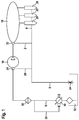
- the feed pump 10 can be arranged on the high-pressure pump 16, integrated into it or arranged remotely from the high-pressure pump 16, for example in the reservoir 12 or in a hydraulic line between the reservoir 12 and the high-pressure pump 16.
- the high-pressure pump 16 has at least one pump element, which in turn has a pump piston which is driven in a lifting movement.
- the high pressure pump 16 may have its own drive shaft through which the lifting movement of the pump piston is effected via a cam or eccentric.
- the drive shaft of the high pressure pump 16 is mechanically driven, for example via a transmission or a belt drive from the internal combustion engine, so that the speed of the high-pressure pump 16 is proportional to the speed of the internal combustion engine.
- the feed pump 10 can be arranged remotely from the at least one high-pressure pump 16, for example also in the storage container 12.
- the feed pump 10 is connected via a hydraulic line 6 to the suction side of the at least one high-pressure pump 16.
- a fuel filter 38 can be arranged in the hydraulic line in order to prevent dirt particles from entering the high-pressure pump 16 and the high-pressure region 18.
- a pressure regulating valve 22 can be provided, by which the pressure prevailing in the high-pressure region 18 is controlled. If an excessively high pressure is present in the high-pressure region 18, excess fuel can reach the reservoir 12 via the hydraulic line 2 in the return line 8 via the pressure regulating valve 22. Thus, in the high-pressure region 18, a required pressure can be set depending on operating parameters of the internal combustion engine.
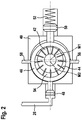
- FIG. 2 is exemplified a pump with adjustable displacement volume in a schematic sectional view of a fuel delivery device. It has a housing 40 in which a rotor 42 with at least one or more vanes 44 is located. The rotor 42 rotates about an axis that passes perpendicular to the blade through a center M1.
- a circular stator ring 46 is clamped by a first actuating piston 48 and a second actuating piston 50.
- the two adjusting pistons are arranged opposite each other. There may be another bearing point of the stator ring 46 by a height adjustment screw, not shown.
- the axis of the circular stator ring 46 passes through a center M2.
- the back of the first actuating piston 48 is acted upon via a hydraulic line 26 with a control pressure.
- the control pressure is in the described embodiment by a Krafftstoff Kunststoff horr within the fuel delivery to the Provided.
- the second actuating piston 50 counteracts the first actuating piston 48 and is held by a spring 52 in a certain position. Due to the control pressure and the spring force, two forces act in opposite directions on the stator ring 46.
- stator 46 is displaced in the housing. If both forces are equal, the stator ring is in the middle position and the two center points M1 and M2 lie on one another. In this case, the flow rate of the fuel is returned to a zero flow rate, i. the flow rate is zero.
- the feed pump 10 can be operated at the same speed or variable speed via a mechanical or electric drive.
- the speed of the feed pump 10 influences the amount of fuel delivered.
- the control pressure can be promoted a variable amount of fuel at the same speed.
- a delivery pump 10 with adjustable delivery volume is the "adjustable vane pump, type PV7" from Bosch Rexroth, which is similar in construction to the described delivery pump 10, but would have to be adapted to the dimensions and requirements of a fuel delivery device.
- an external gear pump or a roller-cell pump or an internal gear pump or a pendulum slide pump can also be used as the delivery pump 10 with adjustable delivery volume.
- An example of a volume-adjustable pendulum slide pump is in the published patent application DE 101 02 531 A1 shown.
- control pressure acts on the first actuating piston 48 and thus influences the displacement volume of the feed pump 10.
- a pressure-side fuel filter 38 is provided, alternatively the pressure on the Suction side of the high pressure pump 16 between the fuel filter 38 and high pressure pump 16 serve as a control pressure.
- the fuel in the return line 8 to the reservoir 12 are controlled by the pressure control valve 22 in the high pressure region 18.
- the pressure control valve 22 may be located directly on the high pressure accumulator 18 or on the high pressure pump 16 or between the high pressure pump 16 and high pressure accumulator 18.
- the pressure control valve 22 is regulated by an electrical control unit. If there is a higher pressure than required in the high-pressure region 18, excess fuel is deactivated with the aid of the pressure regulating valve 22.
- the pressure in the return 8 increases depending on the amount of fuel being removed. The increased fuel return increases the pressure in the Return 8 upstream of the throttle 24 and the control pressure on the first actuating piston 48 increases. The displacement volume of the feed pump 10 is reduced and thus reduces the flow rate of the fuel. If only little fuel is diverted from the pressure control valve 22 into the return 8, the control pressure drops and the delivery pump 10 increases the delivery rate of the fuel.
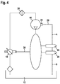
- FIG. 4 shows a further embodiment of the invention.
- the pressure in the high pressure region 18 acts directly on the first control piston 48 of the feed pump 10 and thus affects the displacement of the feed pump 10 prevails in the high-pressure accumulator 18 too high a pressure, the Fuel delivery of the feed pump 10 is reduced, the pressure in the high pressure accumulator 18 is too low, the fuel delivery of the feed pump 10 is increased, otherwise it remains constant.
- the rear side of the second actuating piston 50 can be subjected to a control pressure for the controlled influencing of the displacement volume.
- a force which is composed of the force of the spring 52 and the control pressure acts on the second actuating piston 50.
- the control pressure acting on the second actuating piston 50 comes from any point of the fuel delivery device and should be lower than the control pressure, which acts on the back of the first actuating piston 48.
- FIG. 5 shows a further embodiment of the invention.
- the control pressure is controlled by a pressure control valve 15 which is connected to an electronic control device 19.
- the electrical control device 19 is connected to a pressure sensor 17 in the high-pressure region 18, which supplies information about the pressure in the high-pressure region 18 to the electronic control device 19.
- the electrical control device 19 controls the pressure control valve 15 and thus influenced by the control pressure, the delivery rate of the feed pump 10.
- Unnecessary fuel is via a hydraulic line in the reservoir 12 deactivated.
- the pressure control valve 15 is a continuous adjustment of the force on the second actuating piston 50 of the feed pump 10 is possible.
- the delivery characteristic of the feed pump 10 changes and there are different displacement volumes of the feed pump 10 at the same control pressure.
Landscapes
- Engineering & Computer Science (AREA)
- Mechanical Engineering (AREA)
- General Engineering & Computer Science (AREA)
- Chemical & Material Sciences (AREA)
- Combustion & Propulsion (AREA)
- Physics & Mathematics (AREA)
- Fluid Mechanics (AREA)
- Fuel-Injection Apparatus (AREA)
- Rotary Pumps (AREA)
- Details And Applications Of Rotary Liquid Pumps (AREA)
- Details Of Reciprocating Pumps (AREA)
- Reciprocating Pumps (AREA)
Claims (12)
- Dispositif de refoulement de carburant pour un dispositif d'injection de carburant d'un moteur à combustion interne comprenant une pompe de refoulement (10) et au moins une pompe haute pression (16), du carburant étant refoulé par la pompe de refoulement (10) depuis un réservoir (12) vers le côté d'aspiration de la pompe haute pression (16) et du carburant étant refoulé par la pompe haute pression (16) vers une région haute pression (18), caractérisé en ce que la pompe de refoulement (10) présente un volume de déplacement réglable, de sorte qu'une quantité de carburant variable peut être refoulée pour une même vitesse de rotation de la pompe de refoulement (10), le volume de déplacement réglable étant régulé par le biais d'une pression de commande qui agit par le biais d'une conduite hydraulique (26) sur un piston de commande (48) de la pompe de refoulement (10).
- Dispositif de refoulement de carburant selon la revendication 1, caractérisé en ce que la pompe de refoulement (10) refoule une quantité de carburant variable qui varie entre une quantité de refoulement nulle et une quantité maximale, la quantité maximale étant donnée par le volume de déplacement maximal de la pompe de refoulement (10).
- Dispositif de refoulement de carburant selon la revendication 1, caractérisé en ce que la pression de commande est la pression de carburant du côté pression (6) de la pompe de refoulement (10).
- Dispositif de refoulement de carburant selon la revendication 1, caractérisé en ce que la pression de commande est la pression de carburant entre le filtre à carburant (38) et le côté aspiration de la pompe haute pression (16).
- Dispositif de refoulement de carburant selon la revendication 1, caractérisé en ce que la pression de commande est la pression de carburant dans un retour (8) au réservoir (12).
- Dispositif de refoulement de carburant selon la revendication 1, caractérisé en ce que la pression de commande est la pression de carburant dans l'accumulateur haute pression (18).
- Dispositif de refoulement de carburant selon la revendication 5, caractérisé en ce que le carburant dans le retour (8) au réservoir (12) est coupé par une soupape de débordement (34) du côté aspiration de la pompe haute pression (16).
- Dispositif de refoulement de carburant selon la revendication 5, caractérisé en ce que le carburant dans le retour (8) au réservoir (12) est coupé par une soupape de régulation de pression (22) dans la région haute pression (18).
- Dispositif de refoulement de carburant selon la revendication 1, caractérisé en ce que le volume de déplacement réglable est en outre influencé par le biais d'une pression de régulation.
- Dispositif de refoulement de carburant selon la revendication 9, caractérisé en ce que la pression de régulation est ajustée par le biais d'une soupape de régulation de pression (15).
- Dispositif de refoulement de carburant selon la revendication 9 ou 10, caractérisé en ce que la pression de régulation est ajustée en fonction d'un point de fonctionnement du moteur et/ou en fonction de la pression dans l'accumulateur haute pression (18).
- Dispositif de refoulement de carburant selon la revendication 1, caractérisé en ce que la pompe de refoulement (10) est une pompe à palettes réglable, une pompe à engrenages extérieurs réglable, une pompe cellulaire à rouleaux réglable, une pompe à engrenages intérieurs réglable ou une pompe à tiroir-navette réglable.
Applications Claiming Priority (2)
| Application Number | Priority Date | Filing Date | Title |
|---|---|---|---|
| DE102010031622A DE102010031622A1 (de) | 2010-07-21 | 2010-07-21 | Kraftstofffördereinrichung |
| PCT/EP2011/059556 WO2012010373A1 (fr) | 2010-07-21 | 2011-06-09 | Dispositif de refoulement de carburant |
Publications (2)
| Publication Number | Publication Date |
|---|---|
| EP2596232A1 EP2596232A1 (fr) | 2013-05-29 |
| EP2596232B1 true EP2596232B1 (fr) | 2016-04-20 |
Family
ID=44359860
Family Applications (1)
| Application Number | Title | Priority Date | Filing Date |
|---|---|---|---|
| EP11726103.2A Not-in-force EP2596232B1 (fr) | 2010-07-21 | 2011-06-09 | Dispositif de refoulement de carburant |
Country Status (7)
| Country | Link |
|---|---|
| US (1) | US9328710B2 (fr) |
| EP (1) | EP2596232B1 (fr) |
| JP (1) | JP5693718B2 (fr) |
| KR (1) | KR101867632B1 (fr) |
| CN (1) | CN103003560B (fr) |
| DE (1) | DE102010031622A1 (fr) |
| WO (1) | WO2012010373A1 (fr) |
Families Citing this family (10)
| Publication number | Priority date | Publication date | Assignee | Title |
|---|---|---|---|---|
| US20130336808A1 (en) * | 2012-06-08 | 2013-12-19 | Magna Powertrain Of America, Inc. | Out rotor drive electrical vane pump |
| DE102013207172A1 (de) | 2013-04-19 | 2014-10-23 | Robert Bosch Gmbh | Kraftstofffördereinrichtung für eine Kraftstoffeinspritzeinrichtung einer Brennkraftmaschine |
| CN105473860B (zh) * | 2013-06-13 | 2017-07-25 | 皮尔伯格泵技术有限责任公司 | 可转换润滑剂叶片泵 |
| DE102014215388A1 (de) | 2014-08-05 | 2016-02-11 | Evonik Degussa Gmbh | Stickstoffhaltige Verbindungen, geeignet zur Verwendung bei der Herstellung von Polyurethanen |
| JP2016169843A (ja) * | 2015-03-16 | 2016-09-23 | 日本精工株式会社 | 無段変速機 |
| IT201600125212A1 (it) * | 2016-12-12 | 2018-06-12 | Bosch Gmbh Robert | Pompa elettrica a ingranaggi |
| DE102018216176A1 (de) * | 2018-09-21 | 2020-03-26 | Robert Bosch Gmbh | Kraftstofffördereinrichtung für eine Brennkraftmaschine |
| CN110332112A (zh) * | 2019-06-13 | 2019-10-15 | 江苏理工学院 | 一种比例差压式变量叶片泵 |
| US11092126B2 (en) * | 2019-09-03 | 2021-08-17 | Pratt & Whitney Canada Corp. | Common-rail fuel system with ejector pump and method of use thereof |
| CN112172916A (zh) * | 2020-11-10 | 2021-01-05 | 三一专用汽车有限责任公司 | 转向泵和作业车辆 |
Citations (2)
| Publication number | Priority date | Publication date | Assignee | Title |
|---|---|---|---|---|
| DE10343482A1 (de) * | 2003-09-19 | 2005-04-14 | Robert Bosch Gmbh | Kraftstoffeinspritzeinrichtung für eine Brennkraftmaschine |
| DE102006027486A1 (de) * | 2006-06-14 | 2007-12-20 | Robert Bosch Gmbh | Kraftstoffeinspritzeinrichtung für eine Brennkraftmaschine |
Family Cites Families (18)
| Publication number | Priority date | Publication date | Assignee | Title |
|---|---|---|---|---|
| US2266191A (en) * | 1939-06-05 | 1941-12-16 | Granberg Equipment Inc | Variable displacement pump |
| US4711616A (en) * | 1984-12-13 | 1987-12-08 | Nippondenso Co., Ltd. | Control apparatus for a variable displacement pump |
| JPS61145382A (ja) * | 1984-12-17 | 1986-07-03 | Nippon Denso Co Ltd | 可変容量ポンプの容量制御装置 |
| JP2915626B2 (ja) * | 1990-07-25 | 1999-07-05 | 株式会社ユニシアジェックス | 可変容量型ベーンポンプ |
| DE19612412B4 (de) * | 1996-03-28 | 2006-07-06 | Siemens Ag | Regelung für ein Druckfluid-Versorgungssystem, insbesondere für den Hochdruck in einem Kraftstoff-Einspritzsystem |
| DE19618932C2 (de) | 1996-05-10 | 2001-02-01 | Siemens Ag | Vorrichtung und Verfahren zur Regelung des Kraftstoffdruckes in einem Hochdruckspeicher |
| DE19731994B4 (de) * | 1997-07-25 | 2007-11-15 | Robert Bosch Gmbh | Verfahren und Vorrichtung zur Steuerung einer Brennkraftmaschine |
| DE19853823A1 (de) * | 1998-11-21 | 2000-05-25 | Bosch Gmbh Robert | Verfahren zum Betreiben einer Brennkraftmaschine insbesondere eines Kraftfahrzeugs |
| US6102001A (en) * | 1998-12-04 | 2000-08-15 | Woodward Governor Company | Variable displacement pump fuel metering system and electrohydraulic servo-valve for controlling the same |
| DE10002132A1 (de) * | 2000-01-19 | 2001-08-02 | Siemens Ag | Verfahren und Vorrichtung zur Regelung des Antriebsmoments einer Verbrennungskraftmaschine mit Common-Rail-Einspritzung |
| IT1320684B1 (it) | 2000-10-03 | 2003-12-10 | Fiat Ricerche | Dispositivo di controllo della portata di una pompa ad alta pressionein un impianto di iniezione a collettore comune del combustibile di un |
| DE10059422A1 (de) * | 2000-11-30 | 2002-06-06 | Bosch Gmbh Robert | Vorrichtung zum Fördern von Flüssigkeiten, insbesondere Kraftstoff |
| DE10102531A1 (de) | 2001-01-20 | 2002-07-25 | Guenther Beez | Stelleinrichtung für eine mengenregelbare Zellenpumpe |
| US7108493B2 (en) * | 2002-03-27 | 2006-09-19 | Argo-Tech Corporation | Variable displacement pump having rotating cam ring |
| DE10343480A1 (de) | 2003-09-19 | 2005-04-14 | Robert Bosch Gmbh | Kraftstoffeinspritzeinrichtung für eine Brennkraftmaschine |
| DE102007039892A1 (de) | 2007-08-23 | 2009-02-26 | Continental Automotive Gmbh | Einspritzanlage für eine Brennkraftmaschine |
| US7640916B2 (en) * | 2008-01-29 | 2010-01-05 | Ford Global Technologies, Llc | Lift pump system for a direct injection fuel system |
| US8192172B2 (en) * | 2009-04-06 | 2012-06-05 | Woodward, Inc. | Flow sensing shutoff valve |
-
2010
- 2010-07-21 DE DE102010031622A patent/DE102010031622A1/de not_active Withdrawn
-
2011
- 2011-06-09 CN CN201180035672.0A patent/CN103003560B/zh not_active Expired - Fee Related
- 2011-06-09 WO PCT/EP2011/059556 patent/WO2012010373A1/fr not_active Ceased
- 2011-06-09 EP EP11726103.2A patent/EP2596232B1/fr not_active Not-in-force
- 2011-06-09 JP JP2013520029A patent/JP5693718B2/ja not_active Expired - Fee Related
- 2011-06-09 KR KR1020137001383A patent/KR101867632B1/ko not_active Expired - Fee Related
- 2011-06-09 US US13/808,959 patent/US9328710B2/en not_active Expired - Fee Related
Patent Citations (2)
| Publication number | Priority date | Publication date | Assignee | Title |
|---|---|---|---|---|
| DE10343482A1 (de) * | 2003-09-19 | 2005-04-14 | Robert Bosch Gmbh | Kraftstoffeinspritzeinrichtung für eine Brennkraftmaschine |
| DE102006027486A1 (de) * | 2006-06-14 | 2007-12-20 | Robert Bosch Gmbh | Kraftstoffeinspritzeinrichtung für eine Brennkraftmaschine |
Also Published As
| Publication number | Publication date |
|---|---|
| WO2012010373A1 (fr) | 2012-01-26 |
| JP2013536345A (ja) | 2013-09-19 |
| EP2596232A1 (fr) | 2013-05-29 |
| KR101867632B1 (ko) | 2018-06-15 |
| CN103003560B (zh) | 2017-04-05 |
| KR20130132729A (ko) | 2013-12-05 |
| US9328710B2 (en) | 2016-05-03 |
| JP5693718B2 (ja) | 2015-04-01 |
| CN103003560A (zh) | 2013-03-27 |
| US20130112174A1 (en) | 2013-05-09 |
| DE102010031622A1 (de) | 2012-01-26 |
Similar Documents
| Publication | Publication Date | Title |
|---|---|---|
| EP2596232B1 (fr) | Dispositif de refoulement de carburant | |
| EP1476654B1 (fr) | Dispositif d'injection de carburant pour moteur a combustion interne | |
| EP2032832B1 (fr) | Dispositif d'injection de carburant pour un moteur à combustion interne | |
| EP1352174B1 (fr) | Systeme d'injection de carburant avec regulation de la pression dans la conduite de retour | |
| EP3059438B1 (fr) | Unite de pompe pour une pompe a haute pression | |
| EP2467591B1 (fr) | Dispositif d'alimentation en carburant pour système d'injection de carburant d'un moteur à combustion interne | |
| DE102004005527A1 (de) | Treibstoffzufuhrsystem für eine Verbrennungskraftmaschine | |
| EP1357283B1 (fr) | Dispositif d'injection de carburant pour un moteur à combustion interne | |
| EP1913255B1 (fr) | Dispositif d'alimentation en carburant, destine en particulier a un moteur a combustion | |
| WO2012113488A1 (fr) | Dispositif de refoulement de carburant et procédé d'actionnement d'un dispositif de refoulement de carburant | |
| EP2049800B1 (fr) | Pompe de circulation | |
| DE102010051290A1 (de) | Regelvorrichtung für eine Umlaufschmierung | |
| EP2622204A1 (fr) | Système d'injection de carburant | |
| DE102010027842A1 (de) | Pumpenanordnung | |
| WO2006125702A1 (fr) | Dispositif de transport de carburant pour la surveillance d'un filtre du dispositif | |
| DE102011004939B4 (de) | 02.03.2011Kraftstofffördereinrichtung und Verfahren zum Betätigen einer Kraftstofffördereinrichtung | |
| DE4134184A1 (de) | Verstellbare hydrostatische pumpe | |
| DE10006659B4 (de) | Regeleinrichtung für eine Hydropumpe | |
| EP1515038B1 (fr) | Système de combustible pour un moteur à combustion interne | |
| DE10318941A1 (de) | Kraftstoffsystem für eine Brennkraftmaschine | |
| WO2003069145A1 (fr) | Systeme d'injection de carburant pour un moteur a combustion interne | |
| DE102009047113A1 (de) | Hochdruckpumpe mit mechanischer Vorförderpumpe | |
| DE102009028402A1 (de) | Pumpenanordnung | |
| EP1655480A1 (fr) | Procédé pour utiliser un système de carburant d'un moteur à combustion interne et systéme de carburant | |
| DE102009028439A1 (de) | Pumpenanordnung |
Legal Events
| Date | Code | Title | Description |
|---|---|---|---|
| PUAI | Public reference made under article 153(3) epc to a published international application that has entered the european phase |
Free format text: ORIGINAL CODE: 0009012 |
|
| 17P | Request for examination filed |
Effective date: 20130221 |
|
| AK | Designated contracting states |
Kind code of ref document: A1 Designated state(s): AL AT BE BG CH CY CZ DE DK EE ES FI FR GB GR HR HU IE IS IT LI LT LU LV MC MK MT NL NO PL PT RO RS SE SI SK SM TR |
|
| DAX | Request for extension of the european patent (deleted) | ||
| 17Q | First examination report despatched |
Effective date: 20150123 |
|
| REG | Reference to a national code |
Ref country code: DE Ref legal event code: R079 Ref document number: 502011009533 Country of ref document: DE Free format text: PREVIOUS MAIN CLASS: F02M0063020000 Ipc: F02M0037000000 |
|
| RIC1 | Information provided on ipc code assigned before grant |
Ipc: F04C 14/22 20060101ALI20150930BHEP Ipc: F04C 14/02 20060101ALI20150930BHEP Ipc: F04C 14/26 20060101ALI20150930BHEP Ipc: F02M 69/02 20060101ALI20150930BHEP Ipc: F04C 11/00 20060101ALI20150930BHEP Ipc: F02M 37/00 20060101AFI20150930BHEP Ipc: F02M 63/02 20060101ALI20150930BHEP Ipc: F04C 2/344 20060101ALI20150930BHEP |
|
| GRAP | Despatch of communication of intention to grant a patent |
Free format text: ORIGINAL CODE: EPIDOSNIGR1 |
|
| INTG | Intention to grant announced |
Effective date: 20160105 |
|
| GRAS | Grant fee paid |
Free format text: ORIGINAL CODE: EPIDOSNIGR3 |
|
| GRAA | (expected) grant |
Free format text: ORIGINAL CODE: 0009210 |
|
| AK | Designated contracting states |
Kind code of ref document: B1 Designated state(s): AL AT BE BG CH CY CZ DE DK EE ES FI FR GB GR HR HU IE IS IT LI LT LU LV MC MK MT NL NO PL PT RO RS SE SI SK SM TR |
|
| REG | Reference to a national code |
Ref country code: GB Ref legal event code: FG4D Free format text: NOT ENGLISH |
|
| REG | Reference to a national code |
Ref country code: CH Ref legal event code: EP |
|
| REG | Reference to a national code |
Ref country code: AT Ref legal event code: REF Ref document number: 792729 Country of ref document: AT Kind code of ref document: T Effective date: 20160515 |
|
| REG | Reference to a national code |
Ref country code: IE Ref legal event code: FG4D Free format text: LANGUAGE OF EP DOCUMENT: GERMAN |
|
| REG | Reference to a national code |
Ref country code: DE Ref legal event code: R096 Ref document number: 502011009533 Country of ref document: DE |
|
| REG | Reference to a national code |
Ref country code: FR Ref legal event code: PLFP Year of fee payment: 6 |
|
| REG | Reference to a national code |
Ref country code: LT Ref legal event code: MG4D |
|
| REG | Reference to a national code |
Ref country code: NL Ref legal event code: MP Effective date: 20160420 |
|
| PG25 | Lapsed in a contracting state [announced via postgrant information from national office to epo] |
Ref country code: LT Free format text: LAPSE BECAUSE OF FAILURE TO SUBMIT A TRANSLATION OF THE DESCRIPTION OR TO PAY THE FEE WITHIN THE PRESCRIBED TIME-LIMIT Effective date: 20160420 Ref country code: NL Free format text: LAPSE BECAUSE OF FAILURE TO SUBMIT A TRANSLATION OF THE DESCRIPTION OR TO PAY THE FEE WITHIN THE PRESCRIBED TIME-LIMIT Effective date: 20160420 Ref country code: PL Free format text: LAPSE BECAUSE OF FAILURE TO SUBMIT A TRANSLATION OF THE DESCRIPTION OR TO PAY THE FEE WITHIN THE PRESCRIBED TIME-LIMIT Effective date: 20160420 Ref country code: NO Free format text: LAPSE BECAUSE OF FAILURE TO SUBMIT A TRANSLATION OF THE DESCRIPTION OR TO PAY THE FEE WITHIN THE PRESCRIBED TIME-LIMIT Effective date: 20160720 Ref country code: FI Free format text: LAPSE BECAUSE OF FAILURE TO SUBMIT A TRANSLATION OF THE DESCRIPTION OR TO PAY THE FEE WITHIN THE PRESCRIBED TIME-LIMIT Effective date: 20160420 |
|
| PG25 | Lapsed in a contracting state [announced via postgrant information from national office to epo] |
Ref country code: SE Free format text: LAPSE BECAUSE OF FAILURE TO SUBMIT A TRANSLATION OF THE DESCRIPTION OR TO PAY THE FEE WITHIN THE PRESCRIBED TIME-LIMIT Effective date: 20160420 Ref country code: GR Free format text: LAPSE BECAUSE OF FAILURE TO SUBMIT A TRANSLATION OF THE DESCRIPTION OR TO PAY THE FEE WITHIN THE PRESCRIBED TIME-LIMIT Effective date: 20160721 Ref country code: ES Free format text: LAPSE BECAUSE OF FAILURE TO SUBMIT A TRANSLATION OF THE DESCRIPTION OR TO PAY THE FEE WITHIN THE PRESCRIBED TIME-LIMIT Effective date: 20160420 Ref country code: RS Free format text: LAPSE BECAUSE OF FAILURE TO SUBMIT A TRANSLATION OF THE DESCRIPTION OR TO PAY THE FEE WITHIN THE PRESCRIBED TIME-LIMIT Effective date: 20160420 Ref country code: HR Free format text: LAPSE BECAUSE OF FAILURE TO SUBMIT A TRANSLATION OF THE DESCRIPTION OR TO PAY THE FEE WITHIN THE PRESCRIBED TIME-LIMIT Effective date: 20160420 Ref country code: PT Free format text: LAPSE BECAUSE OF FAILURE TO SUBMIT A TRANSLATION OF THE DESCRIPTION OR TO PAY THE FEE WITHIN THE PRESCRIBED TIME-LIMIT Effective date: 20160822 Ref country code: LV Free format text: LAPSE BECAUSE OF FAILURE TO SUBMIT A TRANSLATION OF THE DESCRIPTION OR TO PAY THE FEE WITHIN THE PRESCRIBED TIME-LIMIT Effective date: 20160420 |
|
| PG25 | Lapsed in a contracting state [announced via postgrant information from national office to epo] |
Ref country code: BE Free format text: LAPSE BECAUSE OF NON-PAYMENT OF DUE FEES Effective date: 20160630 |
|
| REG | Reference to a national code |
Ref country code: DE Ref legal event code: R097 Ref document number: 502011009533 Country of ref document: DE |
|
| PG25 | Lapsed in a contracting state [announced via postgrant information from national office to epo] |
Ref country code: RO Free format text: LAPSE BECAUSE OF FAILURE TO SUBMIT A TRANSLATION OF THE DESCRIPTION OR TO PAY THE FEE WITHIN THE PRESCRIBED TIME-LIMIT Effective date: 20160420 Ref country code: SK Free format text: LAPSE BECAUSE OF FAILURE TO SUBMIT A TRANSLATION OF THE DESCRIPTION OR TO PAY THE FEE WITHIN THE PRESCRIBED TIME-LIMIT Effective date: 20160420 Ref country code: DK Free format text: LAPSE BECAUSE OF FAILURE TO SUBMIT A TRANSLATION OF THE DESCRIPTION OR TO PAY THE FEE WITHIN THE PRESCRIBED TIME-LIMIT Effective date: 20160420 Ref country code: EE Free format text: LAPSE BECAUSE OF FAILURE TO SUBMIT A TRANSLATION OF THE DESCRIPTION OR TO PAY THE FEE WITHIN THE PRESCRIBED TIME-LIMIT Effective date: 20160420 Ref country code: MC Free format text: LAPSE BECAUSE OF FAILURE TO SUBMIT A TRANSLATION OF THE DESCRIPTION OR TO PAY THE FEE WITHIN THE PRESCRIBED TIME-LIMIT Effective date: 20160420 Ref country code: CZ Free format text: LAPSE BECAUSE OF FAILURE TO SUBMIT A TRANSLATION OF THE DESCRIPTION OR TO PAY THE FEE WITHIN THE PRESCRIBED TIME-LIMIT Effective date: 20160420 |
|
| REG | Reference to a national code |
Ref country code: CH Ref legal event code: PL |
|
| PLBE | No opposition filed within time limit |
Free format text: ORIGINAL CODE: 0009261 |
|
| STAA | Information on the status of an ep patent application or granted ep patent |
Free format text: STATUS: NO OPPOSITION FILED WITHIN TIME LIMIT |
|
| PG25 | Lapsed in a contracting state [announced via postgrant information from national office to epo] |
Ref country code: SM Free format text: LAPSE BECAUSE OF FAILURE TO SUBMIT A TRANSLATION OF THE DESCRIPTION OR TO PAY THE FEE WITHIN THE PRESCRIBED TIME-LIMIT Effective date: 20160420 |
|
| GBPC | Gb: european patent ceased through non-payment of renewal fee |
Effective date: 20160720 |
|
| REG | Reference to a national code |
Ref country code: IE Ref legal event code: MM4A |
|
| 26N | No opposition filed |
Effective date: 20170123 |
|
| PG25 | Lapsed in a contracting state [announced via postgrant information from national office to epo] |
Ref country code: CH Free format text: LAPSE BECAUSE OF NON-PAYMENT OF DUE FEES Effective date: 20160630 Ref country code: LI Free format text: LAPSE BECAUSE OF NON-PAYMENT OF DUE FEES Effective date: 20160630 |
|
| PG25 | Lapsed in a contracting state [announced via postgrant information from national office to epo] |
Ref country code: SI Free format text: LAPSE BECAUSE OF FAILURE TO SUBMIT A TRANSLATION OF THE DESCRIPTION OR TO PAY THE FEE WITHIN THE PRESCRIBED TIME-LIMIT Effective date: 20160420 Ref country code: GB Free format text: LAPSE BECAUSE OF NON-PAYMENT OF DUE FEES Effective date: 20160720 Ref country code: IE Free format text: LAPSE BECAUSE OF NON-PAYMENT OF DUE FEES Effective date: 20160609 |
|
| REG | Reference to a national code |
Ref country code: FR Ref legal event code: PLFP Year of fee payment: 7 |
|
| REG | Reference to a national code |
Ref country code: AT Ref legal event code: MM01 Ref document number: 792729 Country of ref document: AT Kind code of ref document: T Effective date: 20160609 |
|
| PG25 | Lapsed in a contracting state [announced via postgrant information from national office to epo] |
Ref country code: AT Free format text: LAPSE BECAUSE OF NON-PAYMENT OF DUE FEES Effective date: 20160609 |
|
| PG25 | Lapsed in a contracting state [announced via postgrant information from national office to epo] |
Ref country code: HU Free format text: LAPSE BECAUSE OF FAILURE TO SUBMIT A TRANSLATION OF THE DESCRIPTION OR TO PAY THE FEE WITHIN THE PRESCRIBED TIME-LIMIT; INVALID AB INITIO Effective date: 20110609 Ref country code: CY Free format text: LAPSE BECAUSE OF FAILURE TO SUBMIT A TRANSLATION OF THE DESCRIPTION OR TO PAY THE FEE WITHIN THE PRESCRIBED TIME-LIMIT Effective date: 20160420 |
|
| REG | Reference to a national code |
Ref country code: FR Ref legal event code: PLFP Year of fee payment: 8 |
|
| PG25 | Lapsed in a contracting state [announced via postgrant information from national office to epo] |
Ref country code: IS Free format text: LAPSE BECAUSE OF FAILURE TO SUBMIT A TRANSLATION OF THE DESCRIPTION OR TO PAY THE FEE WITHIN THE PRESCRIBED TIME-LIMIT Effective date: 20160420 Ref country code: MK Free format text: LAPSE BECAUSE OF FAILURE TO SUBMIT A TRANSLATION OF THE DESCRIPTION OR TO PAY THE FEE WITHIN THE PRESCRIBED TIME-LIMIT Effective date: 20160420 Ref country code: TR Free format text: LAPSE BECAUSE OF FAILURE TO SUBMIT A TRANSLATION OF THE DESCRIPTION OR TO PAY THE FEE WITHIN THE PRESCRIBED TIME-LIMIT Effective date: 20160420 Ref country code: LU Free format text: LAPSE BECAUSE OF NON-PAYMENT OF DUE FEES Effective date: 20160609 Ref country code: MT Free format text: LAPSE BECAUSE OF FAILURE TO SUBMIT A TRANSLATION OF THE DESCRIPTION OR TO PAY THE FEE WITHIN THE PRESCRIBED TIME-LIMIT Effective date: 20160420 |
|
| PG25 | Lapsed in a contracting state [announced via postgrant information from national office to epo] |
Ref country code: BG Free format text: LAPSE BECAUSE OF FAILURE TO SUBMIT A TRANSLATION OF THE DESCRIPTION OR TO PAY THE FEE WITHIN THE PRESCRIBED TIME-LIMIT Effective date: 20160420 |
|
| PG25 | Lapsed in a contracting state [announced via postgrant information from national office to epo] |
Ref country code: AL Free format text: LAPSE BECAUSE OF FAILURE TO SUBMIT A TRANSLATION OF THE DESCRIPTION OR TO PAY THE FEE WITHIN THE PRESCRIBED TIME-LIMIT Effective date: 20160420 |
|
| PGFP | Annual fee paid to national office [announced via postgrant information from national office to epo] |
Ref country code: FR Payment date: 20200623 Year of fee payment: 10 |
|
| PGFP | Annual fee paid to national office [announced via postgrant information from national office to epo] |
Ref country code: IT Payment date: 20200630 Year of fee payment: 10 |
|
| PGFP | Annual fee paid to national office [announced via postgrant information from national office to epo] |
Ref country code: DE Payment date: 20210823 Year of fee payment: 11 |
|
| PG25 | Lapsed in a contracting state [announced via postgrant information from national office to epo] |
Ref country code: FR Free format text: LAPSE BECAUSE OF NON-PAYMENT OF DUE FEES Effective date: 20210630 |
|
| PG25 | Lapsed in a contracting state [announced via postgrant information from national office to epo] |
Ref country code: IT Free format text: LAPSE BECAUSE OF NON-PAYMENT OF DUE FEES Effective date: 20210609 |
|
| REG | Reference to a national code |
Ref country code: DE Ref legal event code: R119 Ref document number: 502011009533 Country of ref document: DE |
|
| PG25 | Lapsed in a contracting state [announced via postgrant information from national office to epo] |
Ref country code: DE Free format text: LAPSE BECAUSE OF NON-PAYMENT OF DUE FEES Effective date: 20230103 |