EP2596734A2 - Haushaltsgerät und Steuerungsverfahren für ein Haushaltsgerät - Google Patents
Haushaltsgerät und Steuerungsverfahren für ein Haushaltsgerät Download PDFInfo
- Publication number
- EP2596734A2 EP2596734A2 EP12193307.1A EP12193307A EP2596734A2 EP 2596734 A2 EP2596734 A2 EP 2596734A2 EP 12193307 A EP12193307 A EP 12193307A EP 2596734 A2 EP2596734 A2 EP 2596734A2
- Authority
- EP
- European Patent Office
- Prior art keywords
- pump
- drain pump
- rinsing
- container
- filling
- Prior art date
- Legal status (The legal status is an assumption and is not a legal conclusion. Google has not performed a legal analysis and makes no representation as to the accuracy of the status listed.)
- Granted
Links
Images


Classifications
-
- A—HUMAN NECESSITIES
- A47—FURNITURE; DOMESTIC ARTICLES OR APPLIANCES; COFFEE MILLS; SPICE MILLS; SUCTION CLEANERS IN GENERAL
- A47L—DOMESTIC WASHING OR CLEANING; SUCTION CLEANERS IN GENERAL
- A47L15/00—Washing or rinsing machines for crockery or tableware
- A47L15/0018—Controlling processes, i.e. processes to control the operation of the machine characterised by the purpose or target of the control
- A47L15/0021—Regulation of operational steps within the washing processes, e.g. optimisation or improvement of operational steps depending from the detergent nature or from the condition of the crockery
- A47L15/0031—Water discharge phases
-
- A—HUMAN NECESSITIES
- A47—FURNITURE; DOMESTIC ARTICLES OR APPLIANCES; COFFEE MILLS; SPICE MILLS; SUCTION CLEANERS IN GENERAL
- A47L—DOMESTIC WASHING OR CLEANING; SUCTION CLEANERS IN GENERAL
- A47L15/00—Washing or rinsing machines for crockery or tableware
- A47L15/0018—Controlling processes, i.e. processes to control the operation of the machine characterised by the purpose or target of the control
- A47L15/0047—Energy or water consumption, e.g. by saving energy or water
-
- A—HUMAN NECESSITIES
- A47—FURNITURE; DOMESTIC ARTICLES OR APPLIANCES; COFFEE MILLS; SPICE MILLS; SUCTION CLEANERS IN GENERAL
- A47L—DOMESTIC WASHING OR CLEANING; SUCTION CLEANERS IN GENERAL
- A47L15/00—Washing or rinsing machines for crockery or tableware
- A47L15/0018—Controlling processes, i.e. processes to control the operation of the machine characterised by the purpose or target of the control
- A47L15/0049—Detection or prevention of malfunction, including accident prevention
-
- A—HUMAN NECESSITIES
- A47—FURNITURE; DOMESTIC ARTICLES OR APPLIANCES; COFFEE MILLS; SPICE MILLS; SUCTION CLEANERS IN GENERAL
- A47L—DOMESTIC WASHING OR CLEANING; SUCTION CLEANERS IN GENERAL
- A47L15/00—Washing or rinsing machines for crockery or tableware
- A47L15/0018—Controlling processes, i.e. processes to control the operation of the machine characterised by the purpose or target of the control
- A47L15/0052—Noise reduction
-
- A—HUMAN NECESSITIES
- A47—FURNITURE; DOMESTIC ARTICLES OR APPLIANCES; COFFEE MILLS; SPICE MILLS; SUCTION CLEANERS IN GENERAL
- A47L—DOMESTIC WASHING OR CLEANING; SUCTION CLEANERS IN GENERAL
- A47L15/00—Washing or rinsing machines for crockery or tableware
- A47L15/42—Details
- A47L15/4202—Water filter means or strainers
- A47L15/4206—Tubular filters
-
- A—HUMAN NECESSITIES
- A47—FURNITURE; DOMESTIC ARTICLES OR APPLIANCES; COFFEE MILLS; SPICE MILLS; SUCTION CLEANERS IN GENERAL
- A47L—DOMESTIC WASHING OR CLEANING; SUCTION CLEANERS IN GENERAL
- A47L15/00—Washing or rinsing machines for crockery or tableware
- A47L15/42—Details
- A47L15/4214—Water supply, recirculation or discharge arrangements; Devices therefor
- A47L15/4225—Arrangements or adaption of recirculation or discharge pumps
-
- A—HUMAN NECESSITIES
- A47—FURNITURE; DOMESTIC ARTICLES OR APPLIANCES; COFFEE MILLS; SPICE MILLS; SUCTION CLEANERS IN GENERAL
- A47L—DOMESTIC WASHING OR CLEANING; SUCTION CLEANERS IN GENERAL
- A47L2401/00—Automatic detection in controlling methods of washing or rinsing machines for crockery or tableware, e.g. information provided by sensors entered into controlling devices
- A47L2401/06—Water supply, circulation or discharge information
-
- A—HUMAN NECESSITIES
- A47—FURNITURE; DOMESTIC ARTICLES OR APPLIANCES; COFFEE MILLS; SPICE MILLS; SUCTION CLEANERS IN GENERAL
- A47L—DOMESTIC WASHING OR CLEANING; SUCTION CLEANERS IN GENERAL
- A47L2401/00—Automatic detection in controlling methods of washing or rinsing machines for crockery or tableware, e.g. information provided by sensors entered into controlling devices
- A47L2401/20—Time, e.g. elapsed operating time
-
- A—HUMAN NECESSITIES
- A47—FURNITURE; DOMESTIC ARTICLES OR APPLIANCES; COFFEE MILLS; SPICE MILLS; SUCTION CLEANERS IN GENERAL
- A47L—DOMESTIC WASHING OR CLEANING; SUCTION CLEANERS IN GENERAL
- A47L2501/00—Output in controlling method of washing or rinsing machines for crockery or tableware, i.e. quantities or components controlled, or actions performed by the controlling device executing the controlling method
- A47L2501/05—Drain or recirculation pump, e.g. regulation of the pump rotational speed or flow direction
Definitions
- the present invention relates to a household appliance, for example a dishwasher, and a control method for such a household appliance.
- a dishwasher has a circulation pump for circulating rinsing liquid in the washing container of the dishwasher and a drain pump for emptying contaminated rinsing liquid from the rinsing container.
- Technically important aspects of the pumps used are low-noise performance and the highest possible delivery rate.
- the drain pump which can also be referred to as a drain pump, is connected to the suction side with a pump pot. Further, the drain pump has a pump chamber in which a pump wheel is running. The pump chamber is in fluid communication with the pump pot in the upper area via a ventilation opening. In this way, the gas collecting above a residual liquid column can escape after the pump impeller has stopped via the vent opening in the pump pot for venting the drain pump. As a result, the impeller dips deeper into the residual liquid of the rinsing liquid. When switched on again, the drainage pump then achieves its maximum delivery capacity in a relatively short time with low-noise performance.
- a water-conducting household appliance with a pump and a vent for this pump is in the DE 10 2009 002 224 A1 described.
- the pump of the household appliance can convey liquid in a normal operating mode.
- the pump can be vented by a vent operating mode that can be carried out before the normal operating mode, while a gas bubble can be conveyed against the conveying direction during the normal operating mode at least partially from a pump chamber of the pump to a liquid pump inlet of the pump.
- an object of the present invention is to provide a vent for a drain pump of a household appliance.
- a domestic appliance in particular a dishwasher, which has a circulating pump for circulating rinsing liquid in a rinsing container of the domestic appliance, a drainage pump for emptying the rinsing liquid from the rinsing container and a control means.
- the control means is adapted to control the drain pump for venting the drain pump after filling the washing container with the washing liquid and before or during operation of the circulation pump.
- the pump chamber of the drain pump is vented by the control of the drain pump according to the invention.
- An advantage of the present invention is, in particular, that the venting of the drainage pump is advanced and carried out before a dirt accumulation occurs, so that the venting can function reliably.
- the drain pump can also be referred to as a drain pump.
- the circulation pump can also be referred to as a heating pump.
- control means is arranged to switch on the drain pump for venting the drain pump after filling the wash tank with the wash liquid and before or during the operation of the circulation pump for a certain period between 2s and 5s.
- the time period is between 2.5s and 3.5s, for example 3s.
- control means is adapted to determine the time duration for switching on the drain pump after filling the washing container with the washing liquid and before or during the operation of the circulation pump in response to a predetermined conveying characteristic of the drain pump.
- the control means selects the duty cycle of the drain pump for the purpose of venting, in particular depending on the type of drain pump used.
- the present invention can be used for many different types of drain pumps.
- control means is adapted to control the drain pump for venting the drain pump after each filling of the washing container with the washing liquid and before or during the operation of the circulation pump.
- control means is adapted to control the drain pump for venting the drain pump between the filling of the washing container with the rinsing liquid and a start-up of the circulating pump.
- control means is adapted to control the drain pump such that for venting the drain pump rinsing liquid is pumped out of the washing after filling the washing with the rinsing liquid and before or during operation of the circulating pump.
- the venting phase can be combined with the pumping process.
- a higher filling quantity of rinsing liquid can be introduced, in order subsequently to again rinse out rinsing liquid in accordance with the quantity of liquid required for the subsequent phase.
- the drain pump is vented and still accumulated dirt is removed by a longer activation time of the drain pump.
- control means is adapted to control the drain pump for venting the drain pump after filling the washing container with the rinsing liquid and during operation of the circulation pump.
- the drain pump can also be vented in the simultaneous operation with the circulation pump directly after filling.
- the controls of the drain pump and the circulation pump are tuned to each other noise optimized.
- control means is arranged to control the drain pump and the circulation pump.
- control means is implemented in the appliance control of the household appliance.
- control means may be implemented by hardware or software technology.
- control means may be designed as a device, for example as a computer, microprocessor, device or as part of the device control of the household appliance.
- control means may be formed as a computer program product, as a function, as a routine, as part of a program code, or as an executable object.
- a method for controlling a domestic appliance in particular a dishwasher, which comprises a circulating pump for circulating rinsing liquid in a rinsing container of the domestic appliance and a drainage pump for emptying the rinsing liquid from the rinsing container.
- the drain pump for venting the drain pump after filling the washing container with the rinsing liquid and before or during operation of the circulating pump is driven.
- the method includes pumping out the flushing liquid from the flushing tank, filling the flushing tank with fresh flushing liquid, actuating the drainage pump to vent the drainage pump, and turning on the circulation pump.
- the above sequence of steps is performed cyclically.
- a computer program product which causes the execution of a method for controlling a household appliance on a program-controlled device.
- the computer program product such as a computer program means can be provided or supplied, for example, as a storage medium, such as a memory card, USB stick, floppy, CD-ROM, DVD or even in the form of a downloadable file from a server in a network. This can be for example in a wireless Communication network by transmitting a corresponding file with the computer program product or the computer program means done.
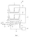
- Fig. 1 is a schematic view of a first embodiment of a dishwasher 10 is shown.
- the dishwasher 10 has a circulation pump 13 and a drain pump 19.
- the circulation pump 13 is for circulating flushing liquid in the washing compartment 1 (see Fig. 4 ) of the dishwasher 10 suitable.
- the drain pump 19 is suitable for emptying the rinsing liquid from the washing compartment 1.
- the control means 23 is adapted to the drain pump 19 for venting the drain pump 19 after filling the washing container 1 with the rinsing liquid and before or during to control an operation of the circulation pump 13. That is, the control means 13 controls the drain pump 19 so that it is vented. The control takes place after the filling of the washing container 1 and before or during the switching on of the circulating pump 13.
- the control means 23 controls the drain pump 19 thereto by means of a first control signal S1 and the circulation pump 13 by means of a second control signal S2.
- the control means 23 controls this for a certain period of time between 2s and 5s. This period of time is in particular between 2.5 s and 3 s. The time period can be determined by the control means 23 as a function of the drain pump 19 used and in particular as a function of the delivery characteristic of the drainage pump 19.
- the drain pump 19 is vented by means of the control by the control means 23 after each filling of the washing container 1 with rinsing liquid.
- the control means 23, the drain pump 19 also control such that after filling the washing container 1 with the rinsing liquid and before or during operation of the circulating pump 13 rinsing fluid from the washing compartment 1 is pumped to vent the drain pump 19.
- the control means 23, the drain pump 19 also control such that after filling the washing container 1 with the rinsing liquid and before or during operation of the circulating pump 13 rinsing fluid from the washing compartment 1 is pumped to vent the drain pump 19.
- more rinsing liquid than necessary for the rinsing is filled in, in order subsequently to pump off a smaller quantity of the rinsing liquid filled in again for the purpose of venting.
- a required rinsing fluid quantity of three liters four liters are filled in the filling step, with another one liter being pumped off in the deaeration step.
- venting of the drain pump 19 by the control means 23 also during operation of the circulation pump 13 can take place.
- control means 23 may be implemented as part of the appliance control of the household appliance.
- FIG. 2 a schematic flow diagram of a first embodiment of a method for controlling a dishwasher 10 is shown.
- a dishwasher 10 which has at least one circulation pump 13 for circulating rinsing liquid in the rinsing container 1 of the dishwasher 10 and an emptying pump 19 for emptying the rinsing liquid from the rinsing container 1 (see Fig. 1 and 4 ).
- step 202 the drain pump 19 is actuated to vent the drain pump 19 after filling the washing container 1 with rinsing liquid and before or during operation of the circulating pump 13.
- Fig. 3 shows a schematic flow diagram of a second embodiment of a method for controlling a dishwasher 10th
- step 301 the existing, contaminated rinsing liquid is pumped out of the washing container 1.
- step 302 the washing container 1 is filled with fresh rinsing liquid.
- step 303 the drain pump 19 is driven so that it is vented.
- step 304 the circulation pump 13 is turned on to circulate the rinsing liquid in the rinsing container 1 in order to rinse the items to be washed introduced into the dishwasher.
- the method starts again with the method step 301. Consequently, the steps 301, 302, 303, 304 are preferably carried out cyclically.
- Fig. 4 is a schematic view of a second embodiment of a dishwasher 10 is shown.
- the dishwasher 10 has a rinsing container 1, in which dishes, not shown, in dish racks 3, 5 can be arranged.
- a rinsing container 1 in which dishes, not shown, in dish racks 3, 5 can be arranged.
- two spraying arms 7, 9 provided in different spraying levels are arranged by way of example as spraying devices, with which the washware to be cleaned is supplied with washing liquid.
- a pump pot 11 is associated with Circulating pump 13 is provided, which is fluidly connected via fluid lines 14, 15, 16 with the spray arms 7, 9.
- the pump pot 11 is further connected to a, connected to the water supply network fresh water supply line 17 and a drain line 18 in connection, in which the drain pump 19 is connected to pump out contaminated rinsing liquid from the washing compartment 1.
- a check valve 27 is connected downstream. Downstream of the check valve 27, a siphon section 29 follows in the sewer line with mutually opposite vertical line sections, so that a liquid column of predetermined height in the reverse direction against the check valve 27 builds up a liquid pressure.
- a filter system for cleaning the circulating in the hydraulic circuit rinsing liquid is provided.
- the filter system has a flat, funnel-shaped fine filter 21, which sits on the top side of the pump pot 11, and a centrally located in the pump pot 11 hollow cylindrical, cup-shaped large filter 22.
- a rinse may include partial program steps with or without liquid feed, such as pre-rinsing, cleaning, intermediate rinsing, rinsing and drying.
- a rinsing fluid change takes place.
- the no longer required, contaminated rinsing liquid is derived by putting the drain pump 19 from the rinsing tank 1 into the waste water supply network.
- fresh water is introduced via the fresh water supply into the pump pot 11.
- the drainage pump 19 can be activated during the flushing process before a liquid change, which takes place after execution of a partial program step, such as the pre-wash, and before the start of the subsequent part program step, such as cleaning.
- a trapped in the pump chamber gas bubble could the time until the drain pump 19 with maximum Output is running, increase. It is therefore the gas bubble from the pump chamber by means of the reference to the Fig. 1 to 3 displaced described venting.
- the venting of the drainage pump 19 can take place immediately after filling the washing container 1 with rinsing liquid and before the start of the circulating pump 13.
Landscapes
- Engineering & Computer Science (AREA)
- Water Supply & Treatment (AREA)
- Washing And Drying Of Tableware (AREA)
- Cookers (AREA)
Abstract
Description
- Die vorliegende Erfindung betrifft ein Haushaltsgerät, beispielsweise eine Geschirrspülmaschine, und ein Steuerungsverfahren für ein solches Haushaltsgerät.
- Eine Geschirrspülmaschine weist eine Umwälzpumpe zum Umwälzen von Spülflüssigkeit in dem Spülbehälter der Geschirrspülmaschine sowie eine Entleerungspumpe zum Entleeren verunreinigter Spülflüssigkeit aus dem Spülbehälter auf. Technisch wichtige Aspekte bei den eingesetzten Pumpen sind ein geräuscharmes Betriebsverhalten sowie eine möglichst hohe Förderleistung.
- Die Entleerungspumpe, welche auch als Laugenpumpe bezeichnet werden kann, ist ansaugseitig mit einem Pumpentopf verbunden. Ferner hat die Entleerungspumpe eine Pumpenkammer, in welcher ein Pumpenrad läuft. Die Pumpenkammer ist im oberen Bereich über eine Belüftungsöffnung mit dem Pumpentopf strömungstechnisch in Verbindung. Auf diese Weise kann das sich oberhalb einer Restflüssigkeitssäule sammelnde Gas nach einem Stillsetzen des Pumpenrades über die Entlüftungsöffnung in dem Pumpentopf zur Entlüftung der Entleerungspumpe entweichen. Das Pumpenrad taucht dadurch tiefer in die Restflüssigkeit der Spülflüssigkeit. Bei erneutem Einschalten erzielt die Entleerungspumpe dann bei einem geräuscharmen Betriebsverhalten ihre maximale Förderleistung in relativ kürzerer Zeit.
- Ein wasserführendes Haushaltsgerät mit einer Pumpe und einer Entlüftungsmöglichkeit für diese Pumpe ist in der
DE 10 2009 002 224 A1 beschrieben. Die Pumpe des Haushaltsgerätes kann in einem Normalbetriebsmodus Flüssigkeit fördern. Ferner ist die Pumpe durch einen vor dem Normalbetriebsmodus durchführbaren Entlüftungsbetriebsmodus entlüftbar, währenddem eine Gasblase entgegen der Förderrichtung während des Normalbetriebsmodus wenigstens teilweise aus einer Pumpenkammer der Pumpe zu einem Flüssigkeitspumpenzulauf der Pumpe förderbar ist. - Vor diesem Hintergrund besteht eine Aufgabe der vorliegenden Erfindung darin, eine Entlüftung für eine Entleerungspumpe eines Haushaltsgerätes zu schaffen.
- Erfindungsgemäß wird ein Haushaltsgerät, insbesondere eine Geschirrspülmaschine, vorgeschlagen, welches eine Umwälzpumpe zum Umwälzen von Spülflüssigkeit in einem Spülbehälter des Haushaltsgeräts, eine Entleerungspumpe zum Entleeren der Spülflüssigkeit aus dem Spülbehälter und ein Steuermittel aufweist. Das Steuermittel ist dazu eingerichtet, die Entleerungspumpe zum Entlüften der Entleerungspumpe nach einem Füllen des Spülbehälters mit der Spülflüssigkeit und vor oder während eines Betriebs der Umwälzpumpe anzusteuern.
- Dabei wird insbesondere die Pumpenkammer der Entleerungspumpe durch die erfindungsgemäße Ansteuerung der Entleerungspumpe entlüftet.
- Ein Vorteil der vorliegenden Erfindung liegt insbesondere darin, dass die Entlüftung der Entleerungspumpe vor einem auftretenden Schmutzanfall vorverlegt und durchgeführt wird, so dass die Entlüftung zuverlässig funktionieren kann.
- Dadurch wird verhindert, dass eine entsprechend große Schmutzmenge vor der Reuse der Entleerungspumpe liegt, welche es verhindern könnte, dass die entsprechende Gasblase in der Pumpenkammer der Entleerungspumpe abtransportiert werden kann. Folglich wird das Auftreten eines solchen Abpumpfehlers zuverlässig verhindert. Ein solcher Abpumpfehler könnte verursachen, dass das Gerät überfüllt wird, was zu einem Austritt von Wasser über die Schürzenkante führen könnte. Wird aber, wie oben ausgeführt, die Pumpenkammer der Entleerungspumpe durch einen kurzen Pumpstoß bereits nach dem Füllen und vor der Inbetriebnahme der Umwälzpumpe nahezu vollständig entlüftet, so wird ein solcher Abpumpfehler verhindert, da an dieser Stelle noch kein wesentlicher Schmutzabtrag stattgefunden haben kann und somit noch keine wesentliche Schmutzfracht vor der Reuse liegen kann. Somit wird die Ansteuerung der Entleerungspumpe derart optimiert, dass der Verlust von Wasser minimiert wird bzw. kein Wasserverlust anfällt. Ferner wird die Wahrscheinlichkeit für das Auftreten des oben angeführten Abpumpfehlers verringert. Des Weiteren ist die Abpumpleistung vom Beginn des Abpumpens an maximiert.
- Durch die erfindungsgemäße Entlüftung der Entleerungspumpe kann ein zuverlässiger Betrieb der Entleerungspumpe auch bei höherem Schmutzanfall sichergestellt werden, ohne etwaige Nachteile durch einen höheren Wasserverbrauch in Kauf nehmen zu müssen.
- Die Entleerungspumpe kann auch als Laugenpumpe bezeichnet werden. Ferner kann die Umwälzpumpe auch als Heizpumpe bezeichnet werden.
- Gemäß einer Ausführungsform ist das Steuermittel dazu eingerichtet, die Entleerungspumpe zum Entlüften der Entleerungspumpe nach dem Füllen des Spülbehälters mit der Spülflüssigkeit und vor oder während des Betriebs der Umwälzpumpe für eine bestimmte Zeitdauer zwischen 2s und 5s einzuschalten. Vorzugsweise liegt die Zeitdauer zwischen 2,5s und 3,5s, beispielsweise bei 3s.
- Folglich wird die Entleerungspumpe derart kurz angesteuert, dass die Einschaltdauer zwar ausreicht, um die Luftblase in der Pumpenkammer der Entleerungspumpe zu entfernen, ein Wasserverlust für das Gerät jedoch minimiert bzw. verhindert wird. Versuche der Anmelderin haben gezeigt, dass eine Einschaltdauer von 2 bis 5s, insbesondere von 3s, für den Pumpstoß optimal ist.
- Gemäß einer weiteren Ausführungsform ist das Steuermittel dazu eingerichtet, die Zeitdauer zum Einschalten der Entleerungspumpe nach dem Füllen des Spülbehälters mit der Spülflüssigkeit und vor oder während des Betriebs der Umwälzpumpe in Abhängigkeit einer vorbestimmten Förder-Kennlinie der Entleerungspumpe zu bestimmen.
- Das Steuermittel wählt die Einschaltdauer der Entleerungspumpe zum Zwecke der Entlüftung insbesondere in Abhängigkeit des Typs der verwendeten Entleerungspumpe. Somit kann die vorliegende Erfindung für viele verschiedene Typen von Entleerungspumpen verwendet werden.
- Gemäß einer weiteren Ausführungsform ist das Steuermittel dazu eingerichtet, die Entleerungspumpe zum Entlüften der Entleerungspumpe nach einem jeden Füllen des Spülbehälters mit der Spülflüssigkeit und vor oder während des Betriebs der Umwälzpumpe anzusteuern.
- Durch das Entlüften der Entleerungspumpe nach einem jeden Füllen des Spülbehälters wird der Wirkungsgrad der vorliegenden Entleerungspumpe maximiert.
- Gemäß einer weiteren Ausführungsform ist das Steuermittel dazu eingerichtet, die Entleerungspumpe zum Entlüften der Entleerungspumpe zwischen dem Füllen des Spülbehälters mit der Spülflüssigkeit und einer Inbetriebnahme der Umwälzpumpe anzusteuern.
- Gemäß einer weiteren Ausführungsform ist das Steuermittel dazu eingerichtet, die Entleerungspumpe derart anzusteuern, dass zum Entlüften der Entleerungspumpe Spülflüssigkeit aus dem Spülbehälter nach dem Füllen des Spülbehälters mit der Spülflüssigkeit und vor oder während des Betriebs der Umwälzpumpe abgepumpt wird.
- Damit kann die Entlüftungsphase mit dem Abpumpvorgang kombiniert werden. Dabei kann zu Beginn einer entsprechenden Phase eine höhere Füllmenge von Spülflüssigkeit eingefüllt werden, um anschließend wiederum Spülflüssigkeit entsprechend der für die nachfolgende Phase benötigten Flüssigkeitsmenge abzupumpen. Auf diese Weise wird die Entleerungspumpe entlüftet und noch angefallener Schmutz wird durch eine längere Ansteuerzeit der Entleerungspumpe entfernt.
- Gemäß einer weiteren Ausführungsform ist das Steuermittel dazu eingerichtet, die Entleerungspumpe zum Entlüften der Entleerungspumpe nach einem Füllen des Spülbehälters mit der Spülflüssigkeit und während des Betriebs der Umwälzpumpe anzusteuern.
- Hierbei kann die Entleerungspumpe auch im gleichzeitigen Betrieb mit der Umwälzpumpe direkt nach dem Befüllen entlüftet werden. Die Ansteuerungen der Entleerungspumpe und der Umwälzpumpe sind dabei geräuschoptimiert aufeinander abgestimmt.
- Gemäß einer weiteren Ausführungsform ist das Steuermittel dazu eingerichtet, die Entleerungspumpe und die Umwälzpumpe zu steuern.
- Gemäß einer weiteren Ausführungsform ist das Steuermittel in der Gerätesteuerung des Haushaltsgeräts implementiert.
- Das Steuermittel kann hardwaretechnisch oder auch softwaretechnisch implementiert sein. Bei einer hardwaretechnischen Implementierung kann das Steuermittel als Vorrichtung, zum Beispiel als Computer, Mikroprozessor, Einrichtung oder auch als Teil der Gerätesteuerung des Haushaltsgeräts ausgebildet sein. Bei einer softwaretechnischen Implementierung kann das Steuermittel als Computerprogrammprodukt, als eine Funktion, als eine Routine, als Teil eines Programmcodes oder als ausführbares Objekt ausgebildet sein.
- Des Weiteren wird ein Verfahren zum Steuern eines Haushaltsgeräts, insbesondere einer Geschirrspülmaschine, vorgeschlagen, welches eine Umwälzpumpe zum Umwälzen von Spülflüssigkeit in einem Spülbehälter des Haushaltsgeräts und eine Entleerungspumpe zum Entleeren der Spülflüssigkeit aus dem Spülbehälter umfasst. Dabei wird die Entleerungspumpe zum Entlüften der Entleerungspumpe nach einem Füllen des Spülbehälters mit der Spülflüssigkeit und vor oder während eines Betriebs der Umwälzpumpe angesteuert.
- Bei einer Ausführungsform beinhaltet das Verfahren das Abpumpen der Spülflüssigkeit aus dem Spülbehälter, das Füllen des Spülbehälters mit frischer Spülflüssigkeit, das Ansteuern der Entleerungspumpe zum Entlüften der Entleerungspumpe und das Einschalten der Umwälzpumpe.
- Bei einer weiteren Ausführungsform wird die obige Abfolge der Schritte zyklisch durchgeführt.
- Weiterhin wird ein Computerprogrammprodukt vorgeschlagen, welches auf einer programmgesteuerten Einrichtung die Durchführung eines Verfahrens zum Steuern eines Haushaltsgeräts veranlasst.
- Das Computerprogrammprodukt wie ein Computerprogramm-Mittel kann beispielsweise als Speichermedium, wie Speicherkarte, USB-Stick, Floppy, CD-ROM, DVD oder auch in Form einer herunterladbaren Datei von einem Server in einem Netzwerk bereitgestellt oder geliefert werden. Dies kann zum Beispiel in einem drahtlosen Kommunikationsnetzwerk durch die Übertragung einer entsprechenden Datei mit dem Computerprogramm-Produkt oder dem Computerprogramm-Mittel erfolgen.
- Weitere vorteilhafte Ausgestaltungen und Aspekte der Erfindung sind Gegenstand der Unteransprüche sowie der im Folgenden beschriebenen Ausführungsbeispiele der Erfindung. Im Weiteren wird die Erfindung anhand von bevorzugten Ausführungsformen unter Bezugnahme auf die beigelegten Figuren näher erläutert.
- Es zeigen dabei:
- Fig. 1
- eine schematische Ansicht eines ersten Ausführungsbeispiels einer Geschirrspülmaschine;
- Fig. 2
- ein schematisches Ablaufdiagramm eines ersten Ausführungsbeispiels eines Verfahrens zur Steuerung einer Geschirrspülmaschine;
- Fig. 3
- ein schematisches Ablaufdiagramm eines zweiten Ausführungsbeispiels eines Verfahrens zur Steuerung einer Geschirrspülmaschine; und
- Fig. 4
- eine schematische Ansicht eines zweiten Ausführungsbeispiels einer Geschirrspülmaschine.
- In den Figuren sind gleiche oder funktionsgleiche Elemente mit denselben Bezugszeichen versehen worden, sofern nichts anderes angegeben ist.
- In
Fig. 1 ist eine schematische Ansicht eines ersten Ausführungsbeispiels einer Geschirrspülmaschine 10 dargestellt. - Die Geschirrspülmaschine 10 hat eine Umwälzpumpe 13 und eine Entleerungspumpe 19. Die Umwälzpumpe 13 ist zum Umwälzen von Spülflüssigkeit in dem Spülbehälter 1 (siehe
Fig. 4 ) der Geschirrspülmaschine 10 geeignet. Die Entleerungspumpe 19 ist zum Entleeren der Spülflüssigkeit aus dem Spülbehälter 1 geeignet. Das Steuermittel 23 ist dazu eingerichtet, die Entleerungspumpe 19 zum Entlüften der Entleerungspumpe 19 nach einem Befüllen des Spülbehälters 1 mit der Spülflüssigkeit und vor oder während eines Betriebs der Umwälzpumpe 13 anzusteuern. Das heißt, das Steuermittel 13 steuert die Entleerungspumpe 19 derart an, dass diese entlüftet wird. Die Ansteuerung erfolgt nach dem Befüllen des Spülbehälters 1 und vor oder während des Einschaltens der Umwälzpumpe 13. - Das Steuermittel 23 steuert die Entleerungspumpe 19 dazu mittels eines ersten Steuersignals S1 und die Umwälzpumpe 13 mittels eines zweiten Steuersignals S2.
- Zum Entlüften der Entleerungspumpe 19 steuert das Steuermittel 23 diese für eine bestimmte Zeitdauer zwischen 2s und 5s an. Diese Zeitdauer liegt insbesondere zwischen 2,5s und 3s. Die Zeitdauer kann von dem Steuermittel 23 in Abhängigkeit der eingesetzten Entleerungspumpe 19 und dabei insbesondere in Abhängigkeit der Förder-Kennlinie der Entleerungspumpe 19 bestimmt werden.
- Ferner wird die Entleerungspumpe 19 mittels der Ansteuerung durch das Steuermittel 23 nach einem jeden Füllen des Spülbehälters 1 mit Spülflüssigkeit entlüftet. Beispielsweise kann das Steuermittel 23 die Entleerungspumpe 19 auch derart ansteuern, dass nach dem Füllen des Spülbehälters 1 mit der Spülflüssigkeit und vor oder während des Betriebs der Umwälzpumpe 13 Spülflüssigkeit aus dem Spülbehälter 1 zum Entlüften der Entleerungspumpe 19 abgepumpt wird. Beispielsweise wird beim Schritt des Füllens des Spülbehälters 1 mit Spülflüssigkeit mehr Spülflüssigkeit als für das Spülen notwendig eingefüllt, um anschließend zum Zwecke der Entlüftung eine kleinere Menge der eingefüllten Spülflüssigkeit wieder abzupumpen. Beispielsweise werden bei einer benötigten Spülflüssigkeitsmenge von drei Litern in dem Befüllungsschritt vier Liter eingefüllt, wobei bei dem Entlüftungsschritt wieder ein Liter abgepumpt wird.
- Alternativ oder zusätzlich kann die Entlüftung der Entleerungspumpe 19 durch das Steuermittel 23 auch während des Betriebs der Umwälzpumpe 13 erfolgen.
- Des Weiteren kann das Steuermittel 23 als Teil der Gerätesteuerung des Haushaltsgeräts implementiert sein.
- In
Fig. 2 ist ein schematisches Ablaufdiagramm eines ersten Ausführungsbeispiels eines Verfahrens zur Steuerung einer Geschirrspülmaschine 10 dargestellt. - In Schritt 201 wird eine Geschirrspülmaschine 10 bereitgestellt, die zumindest eine Umwälzpumpe 13 zum Umwälzen von Spülflüssigkeit in dem Spülbehälter 1 der Geschirrspülmaschine 10 und eine Entleerungspumpe 19 zum Entleeren der Spülflüssigkeit aus dem Spülbehälter 1 aufweist (siehe
Fig. 1 und4 ). - In Schritt 202 wird die Entleerungspumpe 19 zum Entlüften der Entleerungspumpe 19 nach einem Füllen des Spülbehälters 1 mit Spülflüssigkeit und vor oder während eines Betriebs der Umwälzpumpe 13 angesteuert.
-
Fig. 3 zeigt ein schematisches Ablaufdiagramm eines zweiten Ausführungsbeispiels eines Verfahrens zur Steuerung einer Geschirrspülmaschine 10. - In Schritt 301 wird die bestehende, verunreinigte Spülflüssigkeit aus dem Spülbehälter 1 abgepumpt.
- In Schritt 302 wird der Spülbehälter 1 mit frischer Spülflüssigkeit befüllt.
- In Schritt 303 wird die Entleerungspumpe 19 derart angesteuert, dass diese entlüftet wird.
- In Schritt 304 wird die Umwälzpumpe 13 eingeschaltet, um die Spülflüssigkeit in dem Spülbehälter 1 umzuwälzen, um das in die Geschirrspülmaschine eingebrachte Spülgut zu spülen. Nach dem Beenden des Spülvorgangs und damit nach dem Ausschalten der Umwälzpumpe 13 startet das Verfahren wiederum mit dem Verfahrensschritt 301. Folglich werden die Schritte 301, 302, 303, 304 vorzugsweise zyklisch durchgeführt.
- In
Fig. 4 ist eine schematische Ansicht eines zweiten Ausführungsbeispiels einer Geschirrspülmaschine 10 dargestellt. - Die Geschirrspülmaschine 10 hat einen Spülbehälter 1, in dem nicht dargestelltes Spülgut in Geschirrkörben 3, 5 angeordnet werden kann. Im gezeigten Spülbehälter 1 sind beispielhaft als Sprüheinrichtungen zwei in unterschiedlichen Sprühebenen vorgesehene Sprüharme 7, 9 angeordnet, mit denen das zu reinigende Spülgut mit Spülflüssigkeit beaufschlagt wird. Im Spülbehälterboden ist ein Pumpentopf 11 mit zugeordneter Umwälzpumpe 13 vorgesehen, die über Flüssigkeitsleitungen 14, 15, 16 strömungstechnisch mit den Sprüharmen 7, 9 verbunden ist.
- Der Pumpentopf 11 ist ferner mit einer, mit dem Wasserversorgungsnetz gekoppelten Frischwasserzuleitung 17 sowie einer Ablaufleitung 18 in Verbindung, in der die Entleerungspumpe 19 zum Abpumpen verunreinigter Spülflüssigkeit aus dem Spülbehälter 1 geschaltet ist. Außerdem ist der Laugenpumpe 19 ein Rückschlagventil 27 nachgeschaltet. Stromab des Rückschlagventils 27 folgt ein Siphonabschnitt 29 in der Abwasserleitung mit zueinander gegenläufigen vertikalen Leitungsabschnitten, so dass sich eine Flüssigkeitssäule vorgegebener Höhe in Sperrichtung gegen das Rückschlagventil 27 einen Flüssigkeitsdruck aufbaut.
- In dem Pumpentopf 11 ist ein Filtersystem zur Reinigung der im Hydraulikkreislauf umgewälzten Spülflüssigkeit vorgesehen. Das Filtersystem weist einen flächigen, trichterförmigen Feinfilter 21, der oberseitig auf dem Pumpentopf 11 sitzt, und einen mittig im Pumpentopf 11 eingesetzten hohlzylindrischen, topfförmigen Grossfilter 22 auf.
- Während eines Spülganges der Geschirrspülmaschine 10 wird der Betrieb der Pumpen 13, 19 sowie weiterer, hier nicht gezeigter Gerätekomponenten von dem Steuermittel 23 gesteuert. Ein Spülgang kann Teilprogrammschritte mit bzw. ohne Flüssigkeitseinsatz, etwa Vorspülen, Reinigen, Zwischenspülen, Klarspülen und Trocknen, aufweisen.
- Zwischen zwei aufeinander folgenden Teilprogrammschritten mit Flüssigkeitseinsatz, etwa zwischen dem Vorspülen und dem Reinigen, erfolgt ein Spülflüssigkeitswechsel. Bei dem Spülflüssigkeitswechsel wird die nicht mehr benötigte, verunreinigte Spülflüssigkeit durch Inbetriebnahme der Entleerungspumpe 19 aus dem Spülbehälter 1 in das Abwasserversorgungsnetz abgeleitet. Außerdem wird Frischwasser über die Frischwasserzuleitung in den Pumpentopf 11 eingeleitet.
- Die Entleerungspumpe 19 kann während des Spülvorgangs vor einem Flüssigkeitswechsel aktiviert werden, welcher nach Ausführung eines Teilprogrammschritts, etwa dem Vorspülen, und vor Beginn des darauf folgenden Teilprogrammschrittes, etwa dem Reinigen, stattfindet. Eine in der Pumpenkammer gefangene Gasblase könnte die Zeitdauer, bis die Entleerungspumpe 19 mit maximaler Förderleistung läuft, erhöhen. Es wird daher die Gasblase aus der Pumpenkammer mittels der mit Bezug zu den
Fig. 1 bis 3 beschriebenen Entlüftung verdrängt. Die Entlüftung der Entleerungspumpe 19 kann unmittelbar nach dem Befüllen des Spülbehälters 1 mit Spülflüssigkeit und vor der Inbetriebnahme der Umwälzpumpe 13 stattfinden. - Obwohl die vorliegende Erfindung anhand von Ausführungsbeispielen beschrieben wurde, ist sie vielfältig modifizierbar.
-
- 1
- Spülbehälter
- 3, 5
- Geschirrkörbe
- 7, 9
- Sprüharme
- 10
- Geschirrspülmaschine
- 11
- Pumpentopf
- 13
- Umwälzpumpe
- 15, 16
- Flüssigkeitsleitungen
- 17
- Frischwasserzuleitung
- 19
- Laugenpumpe
- 21
- Feinfilter
- 22
- Grobfilter
- 23
- Steuereinrichtung
- 27
- Rückschlagventil
- 29
- Siphonabschnitt
- 201-202
- Verfahrensschritt
- 301-304
- Verfahrensschritt
- S1
- erstes Steuersignal
- S2
- zweites Steuersignal
Claims (13)
- Haushaltsgerät (10), insbesondere Geschirrspülmaschine, mit:einer Umwälzpumpe (13) zum Umwälzen von Spülflüssigkeit in einem Spülbehälter (1) des Haushaltsgeräts (10),einer Entleerungspumpe (19) zum Entleeren der Spülflüssigkeit aus dem Spülbehälter (1), undeinem Steuermittel (23), welches dazu eingerichtet ist, die Entleerungspumpe (19) zum Entlüften der Entleerungspumpe (19) nach einem Füllen des Spülbehälters (1) mit der Spülflüssigkeit und vor oder während eines Betriebs der Umwälzpumpe (13) anzusteuern.
- Haushaltsgerät (10) nach Anspruch 1, dadurch gekennzeichnet, dass das Steuermittel (23) dazu eingerichtet ist, die Entleerungspumpe (19) zum Entlüften der Entleerungspumpe (19) nach dem Füllen des Spülbehälters (1) mit der Spülflüssigkeit und vor oder während des Betriebs der Umwälzpumpe (13) für eine bestimmte Zeitdauer zwischen 2s und 5s, bevorzugt zwischen 2,5s und 3,5s, bevorzugt für 3s, einzuschalten.
- Haushaltsgerät (10) nach Anspruch 2, dadurch gekennzeichnet, dass das Steuermittel (23) dazu eingerichtet ist, die Zeitdauer zum Einschalten der Entleerungspumpe (19) nach dem Füllen des Spülbehälters (1) mit der Spülflüssigkeit und vor oder während des Betriebs der Umwälzpumpe (13) in Abhängigkeit einer vorbestimmten Förder-Kennlinie der Entleerungspumpe (19) zu bestimmen.
- Haushaltsgerät (10) nach einem der Ansprüche 1 bis 3, dadurch gekennzeichnet, dass das Steuermittel (23) dazu eingerichtet ist, die Entleerungspumpe (19) zum Entlüften der Entleerungspumpe (19) nach einem jeden Füllen des Spülbehälters (1) mit der Spülflüssigkeit und vor oder während des Betriebs der Umwälzpumpe (13) anzusteuern.
- Haushaltsgerät (10) nach einem der Ansprüche 1 bis 4, dadurch gekennzeichnet, dass das Steuermittel (23) dazu eingerichtet ist, die Entleerungspumpe (19) zum Entlüften der Entleerungspumpe (19) zwischen dem Füllen des Spülbehälters (1) mit der Spülflüssigkeit und einer Inbetriebnahme der Umwälzpumpe (13) anzusteuern.
- Haushaltsgerät (10) nach einem der Ansprüche 1 bis 5, dadurch gekennzeichnet, dass das Steuermittel (23) dazu eingerichtet ist, die Entleerungspumpe (19) derart anzusteuern, dass Spülflüssigkeit aus dem Spülbehälter (1) zum Entlüften der Entleerungspumpe (19) nach dem Füllen des Spülbehälters (1) mit der Spülflüssigkeit und vor oder während des Betriebs der Umwälzpumpe (13) abgepumpt wird.
- Haushaltsgerät (10) nach einem der Ansprüche 1 bis 6, dadurch gekennzeichnet, dass das Steuermittel (23) dazu eingerichtet ist, die Entleerungspumpe (19) zum Entlüften der Entleerungspumpe (19) nach dem Füllen des Spülbehälters (1) mit der Spülflüssigkeit und während des Betriebs der Umwälzpumpe (13) anzusteuern.
- Haushaltsgerät (10) nach einem der Ansprüche 1 bis 7, dadurch gekennzeichnet, dass das Steuermittel (23) dazu eingerichtet ist, die Entleerungspumpe (19) und die Umwälzpumpe (13) zu steuern.
- Haushaltsgerät (10) nach einem der Ansprüche 1 bis 8, dadurch gekennzeichnet, dass das Steuermittel (23) die Gerätesteuerung des Haushaltsgeräts (10) ist.
- Verfahren zum Steuern eines Haushaltsgeräts (10), insbesondere einer Geschirrspülmaschine, mit einer Umwälzpumpe (13) zum Umwälzen von Spülflüssigkeit in einem Spülbehälter (1) des Haushaltsgeräts (10) und einer Entleerungspumpe (19) zum Entleeren der Spülflüssigkeit aus dem Spülbehälter (1), dadurch gekennzeichnet, dass die Entleerungspumpe (19) zum Entlüften der Entleerungspumpe (19) nach einem Füllen des Spülbehälters (1) mit der Spülflüssigkeit und vor oder während eines Betriebs der Umwälzpumpe (13) angesteuert wird.
- Verfahren nach Anspruch 10, gekennzeichnet durch die Schritte:a) Abpumpen (301) der Spülflüssigkeit aus dem Spülbehälter (1),b) Füllen (302) des Spülbehälters (1) mit frischer Spülflüssigkeit,c) Ansteuern (303) der Entleerungspumpe (19) zum Entlüften der Entleerungspumpe (19), undd) Einschalten (304) der Umwälzpumpe (13).
- Verfahren nach Anspruch 11, dadurch gekennzeichnet, dass die Abfolge der Schritte (301, 302, 303, 304) a) bis d) zyklisch durchgeführt wird.
- Computerprogrammprodukt, welches auf einer programmgesteuerten Einrichtung die Durchführung eines Verfahrens zum Steuern eines Haushaltsgeräts (10) nach einem der Ansprüche 10 bis 12 veranlasst.
Priority Applications (1)
| Application Number | Priority Date | Filing Date | Title |
|---|---|---|---|
| PL12193307T PL2596734T3 (pl) | 2011-11-28 | 2012-11-20 | Urządzenie gospodarstwa domowego i sposób sterowania do urządzenia gospodarstwa domowego |
Applications Claiming Priority (1)
| Application Number | Priority Date | Filing Date | Title |
|---|---|---|---|
| DE102011087168A DE102011087168A1 (de) | 2011-11-28 | 2011-11-28 | Haushaltsgerät und Steuerungsverfahren für ein Haushaltsgerät |
Publications (3)
| Publication Number | Publication Date |
|---|---|
| EP2596734A2 true EP2596734A2 (de) | 2013-05-29 |
| EP2596734A3 EP2596734A3 (de) | 2016-05-11 |
| EP2596734B1 EP2596734B1 (de) | 2018-10-03 |
Family
ID=47221188
Family Applications (1)
| Application Number | Title | Priority Date | Filing Date |
|---|---|---|---|
| EP12193307.1A Active EP2596734B1 (de) | 2011-11-28 | 2012-11-20 | Haushaltsgerät und Steuerungsverfahren für ein Haushaltsgerät |
Country Status (5)
| Country | Link |
|---|---|
| US (2) | US9554687B2 (de) |
| EP (1) | EP2596734B1 (de) |
| DE (1) | DE102011087168A1 (de) |
| PL (1) | PL2596734T3 (de) |
| TR (1) | TR201815257T4 (de) |
Families Citing this family (3)
| Publication number | Priority date | Publication date | Assignee | Title |
|---|---|---|---|---|
| US20130291900A1 (en) * | 2012-05-04 | 2013-11-07 | General Electric Company | Method for operating a pump in an appliance |
| KR102402029B1 (ko) * | 2015-11-13 | 2022-05-26 | 삼성전자주식회사 | 식기 세척기 및 그 제어방법 |
| DE102018209076A1 (de) * | 2018-06-07 | 2019-12-12 | BSH Hausgeräte GmbH | Geschirrspülmaschine, Verfahren zum Betreiben einer Geschirrspülmaschine und Computerprogrammprodukt |
Citations (1)
| Publication number | Priority date | Publication date | Assignee | Title |
|---|---|---|---|---|
| DE102009002224A1 (de) | 2009-04-06 | 2010-10-07 | BSH Bosch und Siemens Hausgeräte GmbH | Wasserführendes Haushaltsgerät, insbesondere Geschirrspülmaschine |
Family Cites Families (3)
| Publication number | Priority date | Publication date | Assignee | Title |
|---|---|---|---|---|
| US6887318B2 (en) | 2003-07-09 | 2005-05-03 | Whirlpool Corporation | Adaptive fill for dishwashers |
| US8105047B2 (en) | 2007-01-05 | 2012-01-31 | Samsung Electronics Co., Ltd. | Electric home appliance having drain function and method of controlling the same |
| EP2009165A1 (de) | 2007-06-28 | 2008-12-31 | Bonferraro S.p.A. | Betriebszyklus für die Entleerungspumpe einer Haushaltswaschmaschine |
-
2011
- 2011-11-28 DE DE102011087168A patent/DE102011087168A1/de not_active Withdrawn
- 2011-12-19 US US13/329,358 patent/US9554687B2/en active Active
-
2012
- 2012-11-20 EP EP12193307.1A patent/EP2596734B1/de active Active
- 2012-11-20 PL PL12193307T patent/PL2596734T3/pl unknown
- 2012-11-20 TR TR2018/15257T patent/TR201815257T4/tr unknown
-
2016
- 2016-11-11 US US15/349,061 patent/US20170055800A1/en not_active Abandoned
Patent Citations (1)
| Publication number | Priority date | Publication date | Assignee | Title |
|---|---|---|---|---|
| DE102009002224A1 (de) | 2009-04-06 | 2010-10-07 | BSH Bosch und Siemens Hausgeräte GmbH | Wasserführendes Haushaltsgerät, insbesondere Geschirrspülmaschine |
Also Published As
| Publication number | Publication date |
|---|---|
| US9554687B2 (en) | 2017-01-31 |
| US20130133699A1 (en) | 2013-05-30 |
| US20170055800A1 (en) | 2017-03-02 |
| PL2596734T3 (pl) | 2019-04-30 |
| EP2596734A3 (de) | 2016-05-11 |
| DE102011087168A1 (de) | 2013-05-29 |
| TR201815257T4 (tr) | 2018-11-21 |
| EP2596734B1 (de) | 2018-10-03 |
Similar Documents
| Publication | Publication Date | Title |
|---|---|---|
| DE102004004104A1 (de) | Geschirrspülmaschine mit alternierendem Pumpenbetrieb | |
| EP2407078A2 (de) | Geschirrspülmaschine | |
| EP4179946B1 (de) | Verfahren zum betreiben eines wasserführenden haushaltsgeräts | |
| EP2759244B1 (de) | Geschirrspülautomat sowie Verfahren zur Einleitung von Frischwasser in einen Geschirrspülautomaten | |
| DE4140949C2 (de) | Niveausteuerung für eine Geschirrspülmaschine | |
| EP2596734B1 (de) | Haushaltsgerät und Steuerungsverfahren für ein Haushaltsgerät | |
| WO2010079021A2 (de) | Verfahren zum abpumpen einer flüssigkeit aus einem wasserführenden haushaltsgerät | |
| EP4306030B1 (de) | Spülmaschine mit schmutzaustragsystem | |
| EP2416694B1 (de) | Wasserführendes haushaltsgerät, insbesondere geschirrspülmaschine | |
| DE102008013549A1 (de) | Geschirrspülmaschine und Verfahren zum Reinigen von Spülgut | |
| EP1699339B1 (de) | Spülmaschinensteuerung zur bewältigung grosser speiserestmengen durch variierbare spülprogramme | |
| DE19828768C2 (de) | Verfahren zum Betreiben einer Geschirrspülmaschine mit einer Umwälzpumpe | |
| EP2420174B1 (de) | Geschirrspülmaschine mit einer verbesserten Abpumpsequenz | |
| DE102017129052B4 (de) | Geschirrspülmaschine | |
| DE19845338B4 (de) | Verfahren zum Betreiben einer Geschirrspülmaschine | |
| EP1699341B1 (de) | Geschirrspülmaschine mit gleichzeitigem Betrieb der Umwälzpumpe und der Laugenpumpe | |
| EP3585238A1 (de) | Geschirrspülmaschine mit hydraulikanordnung zum reinigen einer filtereinrichtung und verfahren | |
| EP3473156B1 (de) | Geschirrspülmaschine | |
| EP2491843B1 (de) | Verfahren zur Durchführung eines Spülprogramms, welches mindestens die Programmabschnitte Reinigen, Zwischenspülen und Klarspülen umfasst | |
| EP1882438A1 (de) | Verfahren zur Durchführung eines Reinigungsprogramms mit einem Sieb-Reinigungsabschnitt | |
| EP4728956A1 (de) | Spülmaschine mit einem tankreinigungssystem | |
| DE102024104056A1 (de) | Filtereinheit für ein Reinigungsgerät, Verfahren und Steuereinheit zum Reinigen einer Filtereinheit und Reinigungsgerät | |
| DE102017106725A1 (de) | Verfahren zum Betreiben eines wasserführenden Reinigungsgeräts und wasserführendes Reinigungsgerät | |
| EP4477128A1 (de) | Verfahren zum betreiben einer gewerblichen spülmaschine sowie spülmaschine | |
| DE102020106792A1 (de) | Spülmaschine mit mindestens einem als rezirkulationskreislauf ausgebildeten waschsystem |
Legal Events
| Date | Code | Title | Description |
|---|---|---|---|
| PUAI | Public reference made under article 153(3) epc to a published international application that has entered the european phase |
Free format text: ORIGINAL CODE: 0009012 |
|
| AK | Designated contracting states |
Kind code of ref document: A2 Designated state(s): AL AT BE BG CH CY CZ DE DK EE ES FI FR GB GR HR HU IE IS IT LI LT LU LV MC MK MT NL NO PL PT RO RS SE SI SK SM TR |
|
| AX | Request for extension of the european patent |
Extension state: BA ME |
|
| RAP1 | Party data changed (applicant data changed or rights of an application transferred) |
Owner name: BSH HAUSGERAETE GMBH |
|
| PUAL | Search report despatched |
Free format text: ORIGINAL CODE: 0009013 |
|
| AK | Designated contracting states |
Kind code of ref document: A3 Designated state(s): AL AT BE BG CH CY CZ DE DK EE ES FI FR GB GR HR HU IE IS IT LI LT LU LV MC MK MT NL NO PL PT RO RS SE SI SK SM TR |
|
| AX | Request for extension of the european patent |
Extension state: BA ME |
|
| RIC1 | Information provided on ipc code assigned before grant |
Ipc: A47L 15/00 20060101AFI20160406BHEP |
|
| 17P | Request for examination filed |
Effective date: 20161111 |
|
| RBV | Designated contracting states (corrected) |
Designated state(s): AL AT BE BG CH CY CZ DE DK EE ES FI FR GB GR HR HU IE IS IT LI LT LU LV MC MK MT NL NO PL PT RO RS SE SI SK SM TR |
|
| R17P | Request for examination filed (corrected) |
Effective date: 20161111 |
|
| 17Q | First examination report despatched |
Effective date: 20180425 |
|
| GRAP | Despatch of communication of intention to grant a patent |
Free format text: ORIGINAL CODE: EPIDOSNIGR1 |
|
| INTG | Intention to grant announced |
Effective date: 20180614 |
|
| GRAS | Grant fee paid |
Free format text: ORIGINAL CODE: EPIDOSNIGR3 |
|
| GRAA | (expected) grant |
Free format text: ORIGINAL CODE: 0009210 |
|
| AK | Designated contracting states |
Kind code of ref document: B1 Designated state(s): AL AT BE BG CH CY CZ DE DK EE ES FI FR GB GR HR HU IE IS IT LI LT LU LV MC MK MT NL NO PL PT RO RS SE SI SK SM TR |
|
| REG | Reference to a national code |
Ref country code: GB Ref legal event code: FG4D Free format text: NOT ENGLISH |
|
| REG | Reference to a national code |
Ref country code: CH Ref legal event code: EP Ref country code: AT Ref legal event code: REF Ref document number: 1047718 Country of ref document: AT Kind code of ref document: T Effective date: 20181015 |
|
| REG | Reference to a national code |
Ref country code: IE Ref legal event code: FG4D Free format text: LANGUAGE OF EP DOCUMENT: GERMAN Ref country code: DE Ref legal event code: R096 Ref document number: 502012013536 Country of ref document: DE |
|
| REG | Reference to a national code |
Ref country code: NL Ref legal event code: MP Effective date: 20181003 |
|
| REG | Reference to a national code |
Ref country code: LT Ref legal event code: MG4D |
|
| PG25 | Lapsed in a contracting state [announced via postgrant information from national office to epo] |
Ref country code: NL Free format text: LAPSE BECAUSE OF FAILURE TO SUBMIT A TRANSLATION OF THE DESCRIPTION OR TO PAY THE FEE WITHIN THE PRESCRIBED TIME-LIMIT Effective date: 20181003 |
|
| PG25 | Lapsed in a contracting state [announced via postgrant information from national office to epo] |
Ref country code: LV Free format text: LAPSE BECAUSE OF FAILURE TO SUBMIT A TRANSLATION OF THE DESCRIPTION OR TO PAY THE FEE WITHIN THE PRESCRIBED TIME-LIMIT Effective date: 20181003 Ref country code: FI Free format text: LAPSE BECAUSE OF FAILURE TO SUBMIT A TRANSLATION OF THE DESCRIPTION OR TO PAY THE FEE WITHIN THE PRESCRIBED TIME-LIMIT Effective date: 20181003 Ref country code: IS Free format text: LAPSE BECAUSE OF FAILURE TO SUBMIT A TRANSLATION OF THE DESCRIPTION OR TO PAY THE FEE WITHIN THE PRESCRIBED TIME-LIMIT Effective date: 20190203 Ref country code: NO Free format text: LAPSE BECAUSE OF FAILURE TO SUBMIT A TRANSLATION OF THE DESCRIPTION OR TO PAY THE FEE WITHIN THE PRESCRIBED TIME-LIMIT Effective date: 20190103 Ref country code: CZ Free format text: LAPSE BECAUSE OF FAILURE TO SUBMIT A TRANSLATION OF THE DESCRIPTION OR TO PAY THE FEE WITHIN THE PRESCRIBED TIME-LIMIT Effective date: 20181003 Ref country code: HR Free format text: LAPSE BECAUSE OF FAILURE TO SUBMIT A TRANSLATION OF THE DESCRIPTION OR TO PAY THE FEE WITHIN THE PRESCRIBED TIME-LIMIT Effective date: 20181003 Ref country code: BG Free format text: LAPSE BECAUSE OF FAILURE TO SUBMIT A TRANSLATION OF THE DESCRIPTION OR TO PAY THE FEE WITHIN THE PRESCRIBED TIME-LIMIT Effective date: 20190103 Ref country code: LT Free format text: LAPSE BECAUSE OF FAILURE TO SUBMIT A TRANSLATION OF THE DESCRIPTION OR TO PAY THE FEE WITHIN THE PRESCRIBED TIME-LIMIT Effective date: 20181003 Ref country code: ES Free format text: LAPSE BECAUSE OF FAILURE TO SUBMIT A TRANSLATION OF THE DESCRIPTION OR TO PAY THE FEE WITHIN THE PRESCRIBED TIME-LIMIT Effective date: 20181003 |
|
| PG25 | Lapsed in a contracting state [announced via postgrant information from national office to epo] |
Ref country code: RS Free format text: LAPSE BECAUSE OF FAILURE TO SUBMIT A TRANSLATION OF THE DESCRIPTION OR TO PAY THE FEE WITHIN THE PRESCRIBED TIME-LIMIT Effective date: 20181003 Ref country code: SE Free format text: LAPSE BECAUSE OF FAILURE TO SUBMIT A TRANSLATION OF THE DESCRIPTION OR TO PAY THE FEE WITHIN THE PRESCRIBED TIME-LIMIT Effective date: 20181003 Ref country code: GR Free format text: LAPSE BECAUSE OF FAILURE TO SUBMIT A TRANSLATION OF THE DESCRIPTION OR TO PAY THE FEE WITHIN THE PRESCRIBED TIME-LIMIT Effective date: 20190104 Ref country code: PT Free format text: LAPSE BECAUSE OF FAILURE TO SUBMIT A TRANSLATION OF THE DESCRIPTION OR TO PAY THE FEE WITHIN THE PRESCRIBED TIME-LIMIT Effective date: 20190203 Ref country code: AL Free format text: LAPSE BECAUSE OF FAILURE TO SUBMIT A TRANSLATION OF THE DESCRIPTION OR TO PAY THE FEE WITHIN THE PRESCRIBED TIME-LIMIT Effective date: 20181003 |
|
| REG | Reference to a national code |
Ref country code: CH Ref legal event code: PL |
|
| REG | Reference to a national code |
Ref country code: DE Ref legal event code: R097 Ref document number: 502012013536 Country of ref document: DE |
|
| PG25 | Lapsed in a contracting state [announced via postgrant information from national office to epo] |
Ref country code: IT Free format text: LAPSE BECAUSE OF FAILURE TO SUBMIT A TRANSLATION OF THE DESCRIPTION OR TO PAY THE FEE WITHIN THE PRESCRIBED TIME-LIMIT Effective date: 20181003 Ref country code: LU Free format text: LAPSE BECAUSE OF NON-PAYMENT OF DUE FEES Effective date: 20181120 Ref country code: DK Free format text: LAPSE BECAUSE OF FAILURE TO SUBMIT A TRANSLATION OF THE DESCRIPTION OR TO PAY THE FEE WITHIN THE PRESCRIBED TIME-LIMIT Effective date: 20181003 |
|
| PLBE | No opposition filed within time limit |
Free format text: ORIGINAL CODE: 0009261 |
|
| STAA | Information on the status of an ep patent application or granted ep patent |
Free format text: STATUS: NO OPPOSITION FILED WITHIN TIME LIMIT |
|
| REG | Reference to a national code |
Ref country code: BE Ref legal event code: MM Effective date: 20181130 |
|
| REG | Reference to a national code |
Ref country code: IE Ref legal event code: MM4A |
|
| PG25 | Lapsed in a contracting state [announced via postgrant information from national office to epo] |
Ref country code: RO Free format text: LAPSE BECAUSE OF FAILURE TO SUBMIT A TRANSLATION OF THE DESCRIPTION OR TO PAY THE FEE WITHIN THE PRESCRIBED TIME-LIMIT Effective date: 20181003 Ref country code: LI Free format text: LAPSE BECAUSE OF NON-PAYMENT OF DUE FEES Effective date: 20181130 Ref country code: SK Free format text: LAPSE BECAUSE OF FAILURE TO SUBMIT A TRANSLATION OF THE DESCRIPTION OR TO PAY THE FEE WITHIN THE PRESCRIBED TIME-LIMIT Effective date: 20181003 Ref country code: SM Free format text: LAPSE BECAUSE OF FAILURE TO SUBMIT A TRANSLATION OF THE DESCRIPTION OR TO PAY THE FEE WITHIN THE PRESCRIBED TIME-LIMIT Effective date: 20181003 Ref country code: EE Free format text: LAPSE BECAUSE OF FAILURE TO SUBMIT A TRANSLATION OF THE DESCRIPTION OR TO PAY THE FEE WITHIN THE PRESCRIBED TIME-LIMIT Effective date: 20181003 Ref country code: CH Free format text: LAPSE BECAUSE OF NON-PAYMENT OF DUE FEES Effective date: 20181130 Ref country code: MC Free format text: LAPSE BECAUSE OF FAILURE TO SUBMIT A TRANSLATION OF THE DESCRIPTION OR TO PAY THE FEE WITHIN THE PRESCRIBED TIME-LIMIT Effective date: 20181003 |
|
| 26N | No opposition filed |
Effective date: 20190704 |
|
| GBPC | Gb: european patent ceased through non-payment of renewal fee |
Effective date: 20190103 |
|
| PG25 | Lapsed in a contracting state [announced via postgrant information from national office to epo] |
Ref country code: FR Free format text: LAPSE BECAUSE OF NON-PAYMENT OF DUE FEES Effective date: 20181203 Ref country code: SI Free format text: LAPSE BECAUSE OF FAILURE TO SUBMIT A TRANSLATION OF THE DESCRIPTION OR TO PAY THE FEE WITHIN THE PRESCRIBED TIME-LIMIT Effective date: 20181003 Ref country code: IE Free format text: LAPSE BECAUSE OF NON-PAYMENT OF DUE FEES Effective date: 20181120 |
|
| PG25 | Lapsed in a contracting state [announced via postgrant information from national office to epo] |
Ref country code: BE Free format text: LAPSE BECAUSE OF NON-PAYMENT OF DUE FEES Effective date: 20181130 |
|
| PG25 | Lapsed in a contracting state [announced via postgrant information from national office to epo] |
Ref country code: GB Free format text: LAPSE BECAUSE OF NON-PAYMENT OF DUE FEES Effective date: 20190103 |
|
| REG | Reference to a national code |
Ref country code: AT Ref legal event code: MM01 Ref document number: 1047718 Country of ref document: AT Kind code of ref document: T Effective date: 20181120 |
|
| PG25 | Lapsed in a contracting state [announced via postgrant information from national office to epo] |
Ref country code: MT Free format text: LAPSE BECAUSE OF FAILURE TO SUBMIT A TRANSLATION OF THE DESCRIPTION OR TO PAY THE FEE WITHIN THE PRESCRIBED TIME-LIMIT Effective date: 20181003 Ref country code: AT Free format text: LAPSE BECAUSE OF NON-PAYMENT OF DUE FEES Effective date: 20181120 |
|
| PG25 | Lapsed in a contracting state [announced via postgrant information from national office to epo] |
Ref country code: MK Free format text: LAPSE BECAUSE OF NON-PAYMENT OF DUE FEES Effective date: 20181003 Ref country code: CY Free format text: LAPSE BECAUSE OF FAILURE TO SUBMIT A TRANSLATION OF THE DESCRIPTION OR TO PAY THE FEE WITHIN THE PRESCRIBED TIME-LIMIT Effective date: 20181003 Ref country code: HU Free format text: LAPSE BECAUSE OF FAILURE TO SUBMIT A TRANSLATION OF THE DESCRIPTION OR TO PAY THE FEE WITHIN THE PRESCRIBED TIME-LIMIT; INVALID AB INITIO Effective date: 20121120 |
|
| PGFP | Annual fee paid to national office [announced via postgrant information from national office to epo] |
Ref country code: DE Payment date: 20251130 Year of fee payment: 14 |
|
| PGFP | Annual fee paid to national office [announced via postgrant information from national office to epo] |
Ref country code: TR Payment date: 20251114 Year of fee payment: 14 |
|
| PGFP | Annual fee paid to national office [announced via postgrant information from national office to epo] |
Ref country code: PL Payment date: 20251114 Year of fee payment: 14 |