EP2596843A1 - Filteranordnung zum Entfernen von in einem Fluid suspendierten Partikeln - Google Patents
Filteranordnung zum Entfernen von in einem Fluid suspendierten Partikeln Download PDFInfo
- Publication number
- EP2596843A1 EP2596843A1 EP11190163.3A EP11190163A EP2596843A1 EP 2596843 A1 EP2596843 A1 EP 2596843A1 EP 11190163 A EP11190163 A EP 11190163A EP 2596843 A1 EP2596843 A1 EP 2596843A1
- Authority
- EP
- European Patent Office
- Prior art keywords
- filter assembly
- filter element
- assembly according
- filter
- chamber
- Prior art date
- Legal status (The legal status is an assumption and is not a legal conclusion. Google has not performed a legal analysis and makes no representation as to the accuracy of the status listed.)
- Withdrawn
Links
- 239000012530 fluid Substances 0.000 title claims abstract description 27
- 239000000428 dust Substances 0.000 claims abstract description 25
- 239000002245 particle Substances 0.000 claims abstract description 7
- 229920000914 Metallic fiber Polymers 0.000 claims abstract description 6
- 239000007769 metal material Substances 0.000 claims abstract description 3
- 238000011144 upstream manufacturing Methods 0.000 claims description 8
- PXHVJJICTQNCMI-UHFFFAOYSA-N Nickel Chemical compound [Ni] PXHVJJICTQNCMI-UHFFFAOYSA-N 0.000 claims description 6
- 229910000831 Steel Inorganic materials 0.000 claims description 5
- 239000010959 steel Substances 0.000 claims description 5
- 238000004140 cleaning Methods 0.000 claims description 4
- RTAQQCXQSZGOHL-UHFFFAOYSA-N Titanium Chemical compound [Ti] RTAQQCXQSZGOHL-UHFFFAOYSA-N 0.000 claims description 3
- 229910045601 alloy Inorganic materials 0.000 claims description 3
- 239000000956 alloy Substances 0.000 claims description 3
- 229910052759 nickel Inorganic materials 0.000 claims description 3
- 239000010935 stainless steel Substances 0.000 claims description 3
- 229910001220 stainless steel Inorganic materials 0.000 claims description 3
- 229910052719 titanium Inorganic materials 0.000 claims description 3
- 239000010936 titanium Substances 0.000 claims description 3
- CWYNVVGOOAEACU-UHFFFAOYSA-N Fe2+ Chemical compound [Fe+2] CWYNVVGOOAEACU-UHFFFAOYSA-N 0.000 claims description 2
- 239000004568 cement Substances 0.000 claims description 2
- 239000000919 ceramic Substances 0.000 claims description 2
- 239000011521 glass Substances 0.000 claims description 2
- 239000000463 material Substances 0.000 claims 1
- 239000004753 textile Substances 0.000 description 9
- 239000011148 porous material Substances 0.000 description 8
- 230000005684 electric field Effects 0.000 description 2
- 230000005484 gravity Effects 0.000 description 2
- 239000002184 metal Substances 0.000 description 2
- 229910052751 metal Inorganic materials 0.000 description 2
- 229920000742 Cotton Polymers 0.000 description 1
- 239000004020 conductor Substances 0.000 description 1
- 238000001816 cooling Methods 0.000 description 1
- 230000000694 effects Effects 0.000 description 1
- 239000000835 fiber Substances 0.000 description 1
- 239000003365 glass fiber Substances 0.000 description 1
- 238000009434 installation Methods 0.000 description 1
- 238000012423 maintenance Methods 0.000 description 1
- 238000004519 manufacturing process Methods 0.000 description 1
- 238000000034 method Methods 0.000 description 1
- 238000003303 reheating Methods 0.000 description 1
Images
Classifications
-
- B—PERFORMING OPERATIONS; TRANSPORTING
- B01—PHYSICAL OR CHEMICAL PROCESSES OR APPARATUS IN GENERAL
- B01D—SEPARATION
- B01D46/00—Filters or filtering processes specially modified for separating dispersed particles from gases or vapours
- B01D46/02—Particle separators, e.g. dust precipitators, having hollow filters made of flexible material
-
- B—PERFORMING OPERATIONS; TRANSPORTING
- B01—PHYSICAL OR CHEMICAL PROCESSES OR APPARATUS IN GENERAL
- B01D—SEPARATION
- B01D39/00—Filtering material for liquid or gaseous fluids
- B01D39/14—Other self-supporting filtering material ; Other filtering material
- B01D39/20—Other self-supporting filtering material ; Other filtering material of inorganic material, e.g. asbestos paper, metallic filtering material of non-woven wires
- B01D39/2027—Metallic material
-
- B—PERFORMING OPERATIONS; TRANSPORTING
- B01—PHYSICAL OR CHEMICAL PROCESSES OR APPARATUS IN GENERAL
- B01D—SEPARATION
- B01D46/00—Filters or filtering processes specially modified for separating dispersed particles from gases or vapours
- B01D46/0027—Filters or filtering processes specially modified for separating dispersed particles from gases or vapours with additional separating or treating functions
- B01D46/0032—Filters or filtering processes specially modified for separating dispersed particles from gases or vapours with additional separating or treating functions using electrostatic forces to remove particles, e.g. electret filters
-
- B—PERFORMING OPERATIONS; TRANSPORTING
- B01—PHYSICAL OR CHEMICAL PROCESSES OR APPARATUS IN GENERAL
- B01D—SEPARATION
- B01D46/00—Filters or filtering processes specially modified for separating dispersed particles from gases or vapours
- B01D46/24—Particle separators, e.g. dust precipitators, using rigid hollow filter bodies
- B01D46/2403—Particle separators, e.g. dust precipitators, using rigid hollow filter bodies characterised by the physical shape or structure of the filtering element
- B01D46/2407—Filter candles
-
- B—PERFORMING OPERATIONS; TRANSPORTING
- B01—PHYSICAL OR CHEMICAL PROCESSES OR APPARATUS IN GENERAL
- B01D—SEPARATION
- B01D46/00—Filters or filtering processes specially modified for separating dispersed particles from gases or vapours
- B01D46/42—Auxiliary equipment or operation thereof
- B01D46/50—Means for discharging electrostatic potential
Definitions
- the present invention generally relates to a filter assembly for removing particulates suspended in a fluid.
- the invention more particularly relates to a dedusting apparatus for treating off-gas from a metallurgical reactor, e.g. a blast furnace.
- baghouse a device commonly referred to as baghouse.
- a baghouse comprises a housing with a first chamber for receiving the dirty, dust-laden gas and a second chamber for feeding clean, dust-free gas to a subsequent treatment device.
- the cleaning of the gas is performed by tubular filter elements arranged in a tube sheet separating the first chamber from the second chamber.
- the filter elements are textile filter media formed from cotton, plastic fibre or glass fibre.
- dirty, dust-laden gas is fed through a gas inlet into the first chamber.
- the gas then flows through the textile filter media into the interior space within the core of the tubular filter element.
- the dust is caught by the filter element and either sticks thereto or falls under gravity to the bottom of the first chamber.
- the clean gas in the interior space within the core of the tubular filter element is fed to the second chamber from where it is let out of the baghouse via a gas outlet.
- the dust accumulating at the bottom of the first chamber is extracted from the baghouse and disposed of. The dust that sticks to the filter element tends to clog the filter and, after a while, it becomes necessary to clean the filter.
- a knocking device may be provided for causing the filter elements to vibrate and thereby liberate the dust stuck thereto.
- Textile filter elements have the disadvantage that they cannot be used with high temperature gasses. Indeed, the maximum temperature allowed by textile filter elements is generally in the region of 150°C, maximum 300°C. Off-gas from e.g. a metallurgical furnace is however generally at a higher temperature. Consequently the off-gas has to be cooled before it is fed though the baghouse. This causes a loss of energy, which is in particular undesired as the gas may have to be heated again downstream of the baghouse for further use.
- Another commonly known device for removing dust from a gas stream is an electrostatic device.
- the dust is electronically charged and collected through the action of an electric field.
- the dust-laden gas is fed through a chamber comprising a first electrode maintained at high voltage and a second electrode maintained at low voltage or ground. As the gas passes therethrough, the electric field between the two electrodes charges the dust, which is then attracted to the second electrode.
- US 2009/0158926 suggests combining a baghouse type device with an electrostatic device.
- the typical baghouse filter element is replaced with a filter assembly comprising a filter element section and a pre-collector body.
- An electrode is furthermore arranged in the first chamber of the housing.
- the filter assembly comprises a tubular textile filter element connected with a first end to the tube sheet separating the first chamber from the second chamber, at the second end of the tubular textile filter element, a pre-collector body is attached.
- This pre-collector body is a cylindrical element made from conductive material and configured to be connected to an electrical potential.
- a high voltage is applied to the electrode arranged in the first chamber and a considerably lower voltage, or ground, is applied to the pre-collector body.
- a substantive portion of the dust is attracted by the pre-collector body, the remaining dust being collected by the textile filter element.
- Electrostatic devices may allow the gas to be at a higher temperature, it should be noted that the temperature of the second electrode should be kept low to minimise sticking of dust thereto. Electrostatic devices are generally also known for their relatively high installation and maintenance costs.
- the combination device of US 2009/0158926 uses textile filter elements, thereby only allowing relatively low temperature gasses to be fed therethrough, in combination with an expensive electrostatic device.
- the object of the present invention is to provide an alternative filter assembly for removing particulates suspended in a fluid, in particular wherein the fluid may be fed through the assembly at higher temperatures. This object is achieved by a filter assembly as claimed in claim 1.
- the present invention proposes a filter assembly for removing particulates suspended in a fluid, in particular for removing dust particles from a gas, the filter assembly comprising a housing divided into a first chamber and a second chamber by a tube sheet, the first chamber being in fluid communication with a fluid inlet and the second chamber being in fluid communication with a fluid outlet.
- the filter assembly further comprises at least one tubular filter element having one open end and one closed end, the open end being arranged in an opening of the tube sheet and the closed end protruding into one of the first and second chambers, the open end opening into the other one of the first and second chambers.
- the filter element is a metallic filter element.
- the filter element is a metallic filter element
- high temperature gasses may be fed through the filter assembly. Indeed, the maximum temperature allowed may be as high as 1000°C, depending on the type of metal used.
- Off-gas from e.g. a metallurgical furnace does not have to be cooled, or at least not as much, before it is fed though the baghouse. This may lead to considerable energy savings, even more so if it is desired to use the off-gas at a high temperature downstream of the filter assembly. It is clear that the cooling of the off-gas upstream of the filter assembly and the subsequent reheating thereof downstream of the filter assembly, would lead to considerable energy losses, which can be avoided by the filter assembly according to the present invention.
- the filter element may be flexible or rigid.
- the metallic fibres are chosen from the group comprising steel, stainless steel, titanium, nickel and FeCrAl-alloys.
- the filter element may have a porosity between 1 and 300 ⁇ m, preferably between 5 and 150 ⁇ m.
- the filter element can have a thickness between 1 and 3 mm, preferably between 1.2 and 1.8 mm.
- the filter assembly further comprises at least one discharge electrode arranged upstream of the tube sheet, the discharge electrode being connected to a first electric potential, the filter element being connected to a second electric potential.
- a high voltage may be applied to the discharge electrode and a considerably lower voltage, or ground, may be applied to the filter element.
- Dust-laden gas is fed through the filter assembly, a substantial portion of the dust is electrically attracted to the filter element, the remaining dust being caught in the pores of the filter element. Dust is thus not only caught in the pores of the filter element, but also on the wall portions of the filter element, i.e. the area between the pores.
- the use of the discharge electrode allows for the pores of the filter element to be of larger size, which reduces pressures loss across the filter assembly and increases the flow rate of gas through the filter assembly.
- the filter element may e.g. be electrically connected to the tube sheet and the tube sheet may be electrically connected to the housing, the housing being connected to a second electric potential.
- the discharge electrode is connected to a high voltage supply; and the filter element is connected to earth.
- the at least one discharge electrode is arranged within the first chamber of the housing.
- the at least one discharge electrode may also be arranged in a charging apparatus upstream of the housing.
- the first chamber may comprise a funnel shaped bottom section for collecting particulates removed from the fluid and a particulate outlet for removing collected particulates from the housing.
- a further object of the present invention is to provide a method for cleaning off-gas in the steel, non-ferrous, ceramics, cement or glass industry, in foundries or in energy generation. This object is achieved by the use of a filter assembly as described above in an off-gas cleaning plant.
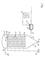
- FIG. 1 schematically shows a filter assembly 10 for removing dust particles from a gas.
- the filter assembly 10 comprises a housing 12 divided into a first chamber 14 and a second chamber 16.
- the first chamber 14 has a fluid inlet 18 connected to a feed pipe 20 for feeding dust-laden gas into the housing 12.
- the second chamber 16 has a fluid outlet 22 connected to a discharge pipe 24.
- a tube sheet 26 is arranged in the housing 12 for dividing the latter into the first and second chambers 14, 16.
- the tube sheet 26 comprises a plurality of openings 28, wherein a tubular filter element 30 is arranged in each such opening 28.
- the filter element 30 has an open end 32 connected to the tube sheet 26 and a closed end 34 arranged at a distance from the tube sheet 26.
- the tube sheet 26 is arranged in an upper portion of the housing 12 and the filter elements 30 extend from the tube sheet 26 into the first chamber 14 of the housing 12.
- the filter elements 30, which according to the present invention are metallic filter elements 30, may be made from metallic fibres, e.g. chosen from the group comprising steel, stainless steel, titanium, nickel and FeCrAl-alloys.
- Such filter elements 30 are heat resistant and allow high temperature gasses to be fed through the filter assembly.
- the maximum temperature allowed may be as high as 1000°C.
- the filter elements 30 may be designed to be flexible or rigid.
- the filter elements 30 can have a porosity between 5 and 150 ⁇ m and a thickness between 1.2 and 1.8 mm.
- dust-laden gas is fed through the feed pipe 20 into the first chamber 14 of the housing 12 via the fluid inlet 18.
- the gas then flows through the filter elements 30 into the interior space within the core of the filter elements 30.
- the dust is caught by the filter elements 30 and either sticks thereto or falls under gravity to the bottom of the first chamber 14.
- the clean gas in the interior space within the core of the filter element 30 is fed to the second chamber 16 from where it is let out of the housing 12 via the fluid outlet 22 connected to the discharge pipe 24.
- the dust accumulating at the bottom of the first chamber 14 is extracted from the housing 12 and disposed of.
- the first chamber 14 of the housing 12 comprises a funnel shaped bottom section 36 leading to a particulate outlet 38 connected to a particulate evacuation line 40.
- the filter assembly 10 further comprises a discharge electrode 42 arranged upstream of the tube sheet 26, in particular upstream of the filter elements 30.
- the discharge electrode 42 is connected to a first electric potential, e.g. a high voltage supply 44, while the filter elements 30 are connected to a second electric potential, e.g. earth 46.
- a first electric potential e.g. a high voltage supply 44
- the filter elements 30 are connected to a second electric potential, e.g. earth 46.
- a substantial portion of the charged dust particles are electrically attracted to the filter elements 30, the remaining dust particles being caught in the pores of the filter elements 30. Dust particles are thus not only caught in the pores of the filter elements 30, but also on the wall portions thereof, i.e. the area between the pores.
- the discharge electrode 42 is arranged in a charging apparatus 48 within the feed pipe 20 upstream of the housing 12.
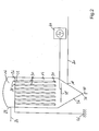
- FIG. 2 schematically shows filter assembly 10 according to a second embodiment of the invention. This embodiment is similar to the one shown in Figure 1 . Identical elements are represented by identical reference signs and are hereunder not repeated in detail.
- the discharge electrode 42' is arranged in the first chamber 16 of the housing 12.
Landscapes
- Chemical & Material Sciences (AREA)
- Chemical Kinetics & Catalysis (AREA)
- Physics & Mathematics (AREA)
- Geometry (AREA)
- Life Sciences & Earth Sciences (AREA)
- Geology (AREA)
- Filtering Of Dispersed Particles In Gases (AREA)
Priority Applications (1)
| Application Number | Priority Date | Filing Date | Title |
|---|---|---|---|
| EP11190163.3A EP2596843A1 (de) | 2011-11-22 | 2011-11-22 | Filteranordnung zum Entfernen von in einem Fluid suspendierten Partikeln |
Applications Claiming Priority (1)
| Application Number | Priority Date | Filing Date | Title |
|---|---|---|---|
| EP11190163.3A EP2596843A1 (de) | 2011-11-22 | 2011-11-22 | Filteranordnung zum Entfernen von in einem Fluid suspendierten Partikeln |
Publications (1)
| Publication Number | Publication Date |
|---|---|
| EP2596843A1 true EP2596843A1 (de) | 2013-05-29 |
Family
ID=45093413
Family Applications (1)
| Application Number | Title | Priority Date | Filing Date |
|---|---|---|---|
| EP11190163.3A Withdrawn EP2596843A1 (de) | 2011-11-22 | 2011-11-22 | Filteranordnung zum Entfernen von in einem Fluid suspendierten Partikeln |
Country Status (1)
| Country | Link |
|---|---|
| EP (1) | EP2596843A1 (de) |
Cited By (1)
| Publication number | Priority date | Publication date | Assignee | Title |
|---|---|---|---|---|
| CN110102114A (zh) * | 2019-03-27 | 2019-08-09 | 林海辉 | 一种基于气动循环进行静电消除的碳粉过滤装置 |
Citations (5)
| Publication number | Priority date | Publication date | Assignee | Title |
|---|---|---|---|---|
| US4354858A (en) * | 1980-07-25 | 1982-10-19 | General Electric Company | Method for filtering particulates |
| DE3600293A1 (de) * | 1986-01-08 | 1987-07-09 | Krupp Gmbh | Verfahren und vorrichtung zur mehrstufigen verbrennung fossiler brennstoffe |
| US5112368A (en) * | 1990-08-27 | 1992-05-12 | Biothermica International Inc. | Process for removing dust from high temperature gas streams |
| US20090158926A1 (en) | 2007-12-20 | 2009-06-25 | Bha Group, Inc. | Systems and methods for removal of particulate matter in a filtration system |
| US20100101737A1 (en) * | 2007-03-15 | 2010-04-29 | Kiekens Filip Rene Irena | Filter Assembly Containing Metal Fibre Filter Elements |
-
2011
- 2011-11-22 EP EP11190163.3A patent/EP2596843A1/de not_active Withdrawn
Patent Citations (5)
| Publication number | Priority date | Publication date | Assignee | Title |
|---|---|---|---|---|
| US4354858A (en) * | 1980-07-25 | 1982-10-19 | General Electric Company | Method for filtering particulates |
| DE3600293A1 (de) * | 1986-01-08 | 1987-07-09 | Krupp Gmbh | Verfahren und vorrichtung zur mehrstufigen verbrennung fossiler brennstoffe |
| US5112368A (en) * | 1990-08-27 | 1992-05-12 | Biothermica International Inc. | Process for removing dust from high temperature gas streams |
| US20100101737A1 (en) * | 2007-03-15 | 2010-04-29 | Kiekens Filip Rene Irena | Filter Assembly Containing Metal Fibre Filter Elements |
| US20090158926A1 (en) | 2007-12-20 | 2009-06-25 | Bha Group, Inc. | Systems and methods for removal of particulate matter in a filtration system |
Non-Patent Citations (1)
| Title |
|---|
| RICHBER K-H: "METALLISCHE GASFILTER. ÖANWENDUNGSBEISPIELE AUS DER PRAXIS", CHEMIETECHNIK, HUTHIG, HEIDELBERG, DE, vol. 24, no. 1, 1 January 1995 (1995-01-01), pages 38 - 40, XP000489719, ISSN: 0340-9961 * |
Cited By (1)
| Publication number | Priority date | Publication date | Assignee | Title |
|---|---|---|---|---|
| CN110102114A (zh) * | 2019-03-27 | 2019-08-09 | 林海辉 | 一种基于气动循环进行静电消除的碳粉过滤装置 |
Similar Documents
| Publication | Publication Date | Title |
|---|---|---|
| US3577705A (en) | Filter system | |
| US4904283A (en) | Enhanced fabric filtration through controlled electrostatically augmented dust deposition | |
| US20110209620A1 (en) | Electric dust collector | |
| CN102811818A (zh) | 改进的颗粒物质控制设备和方法 | |
| KR101577340B1 (ko) | 복합형 집진 장치 | |
| JP2015160158A (ja) | 集塵装置の運転方法及び集塵装置 | |
| CN205914281U (zh) | 一种电收尘器 | |
| CN103736604A (zh) | 一种旋风湿式静电除尘器 | |
| RU2448758C2 (ru) | Рукавный фильтр для очистки газа от пыли с короткоимпульсной продувкой | |
| RU2419478C1 (ru) | Комбинированный электрофильтр | |
| EP2596843A1 (de) | Filteranordnung zum Entfernen von in einem Fluid suspendierten Partikeln | |
| CN103961962B (zh) | 一种静电与无机多孔陶瓷管复合的含尘气体净化装置 | |
| CN105903294A (zh) | 一种免反吹的颗粒床气体净化器及净化方法 | |
| EP3423191B1 (de) | Vorrichtung und verfahren zur entstaubung eines gases | |
| JP6249181B2 (ja) | バグフィルタ式集塵装置およびその運転方法 | |
| RU2483780C1 (ru) | Электрофильтр с фильтрующими элементами | |
| CN115007314B (zh) | 一种耦合增强电袋复合除尘装置 | |
| CN118594153A (zh) | 一种高烟尘废气过滤吸附装置 | |
| JP5423418B2 (ja) | トリクロロシラン製造装置 | |
| JP4933445B2 (ja) | セルフクリーニング及び電圧制御式の静電ろ過方法及び静電ろ過装置 | |
| CN110448963A (zh) | 一种含尘气体的除尘方法及装置 | |
| CN204601842U (zh) | 一种高温气固过滤分离装置 | |
| CN212141810U (zh) | 一种导电布袋除尘器 | |
| WO2006090549A1 (ja) | ガス濾過装置 | |
| JP3597713B2 (ja) | ガスフィルター装置 |
Legal Events
| Date | Code | Title | Description |
|---|---|---|---|
| PUAI | Public reference made under article 153(3) epc to a published international application that has entered the european phase |
Free format text: ORIGINAL CODE: 0009012 |
|
| AK | Designated contracting states |
Kind code of ref document: A1 Designated state(s): AL AT BE BG CH CY CZ DE DK EE ES FI FR GB GR HR HU IE IS IT LI LT LU LV MC MK MT NL NO PL PT RO RS SE SI SK SM TR |
|
| AX | Request for extension of the european patent |
Extension state: BA ME |
|
| STAA | Information on the status of an ep patent application or granted ep patent |
Free format text: STATUS: THE APPLICATION IS DEEMED TO BE WITHDRAWN |
|
| 18D | Application deemed to be withdrawn |
Effective date: 20131130 |