EP2597014A2 - Système de direction électrique - Google Patents
Système de direction électrique Download PDFInfo
- Publication number
- EP2597014A2 EP2597014A2 EP12193816.1A EP12193816A EP2597014A2 EP 2597014 A2 EP2597014 A2 EP 2597014A2 EP 12193816 A EP12193816 A EP 12193816A EP 2597014 A2 EP2597014 A2 EP 2597014A2
- Authority
- EP
- European Patent Office
- Prior art keywords
- end portion
- worm
- bearing
- worm shaft
- urging
- Prior art date
- Legal status (The legal status is an assumption and is not a legal conclusion. Google has not performed a legal analysis and makes no representation as to the accuracy of the status listed.)
- Granted
Links
- 230000007423 decrease Effects 0.000 claims abstract description 9
- 239000003638 chemical reducing agent Substances 0.000 claims description 10
- 230000007935 neutral effect Effects 0.000 claims description 6
- 230000000717 retained effect Effects 0.000 claims description 2
- 239000002184 metal Substances 0.000 description 5
- 229920003002 synthetic resin Polymers 0.000 description 4
- 239000000057 synthetic resin Substances 0.000 description 4
- 238000006243 chemical reaction Methods 0.000 description 2
- 230000008878 coupling Effects 0.000 description 2
- 238000010168 coupling process Methods 0.000 description 2
- 238000005859 coupling reaction Methods 0.000 description 2
- 238000004519 manufacturing process Methods 0.000 description 2
- 229920005989 resin Polymers 0.000 description 2
- 239000011347 resin Substances 0.000 description 2
- 230000006835 compression Effects 0.000 description 1
- 238000007906 compression Methods 0.000 description 1
- 230000003247 decreasing effect Effects 0.000 description 1
- 238000006073 displacement reaction Methods 0.000 description 1
- 239000004519 grease Substances 0.000 description 1
- 239000000314 lubricant Substances 0.000 description 1
- 238000000465 moulding Methods 0.000 description 1
- 230000035939 shock Effects 0.000 description 1
- 229910001220 stainless steel Inorganic materials 0.000 description 1
- 239000010935 stainless steel Substances 0.000 description 1
Images

Classifications
-
- B—PERFORMING OPERATIONS; TRANSPORTING
- B62—LAND VEHICLES FOR TRAVELLING OTHERWISE THAN ON RAILS
- B62D—MOTOR VEHICLES; TRAILERS
- B62D5/00—Power-assisted or power-driven steering
- B62D5/04—Power-assisted or power-driven steering electrical, e.g. using an electric servo-motor connected to, or forming part of, the steering gear
- B62D5/0403—Power-assisted or power-driven steering electrical, e.g. using an electric servo-motor connected to, or forming part of, the steering gear characterised by constructional features, e.g. common housing for motor and gear box
-
- B—PERFORMING OPERATIONS; TRANSPORTING
- B62—LAND VEHICLES FOR TRAVELLING OTHERWISE THAN ON RAILS
- B62D—MOTOR VEHICLES; TRAILERS
- B62D5/00—Power-assisted or power-driven steering
- B62D5/04—Power-assisted or power-driven steering electrical, e.g. using an electric servo-motor connected to, or forming part of, the steering gear
- B62D5/0409—Electric motor acting on the steering column
-
- F—MECHANICAL ENGINEERING; LIGHTING; HEATING; WEAPONS; BLASTING
- F16—ENGINEERING ELEMENTS AND UNITS; GENERAL MEASURES FOR PRODUCING AND MAINTAINING EFFECTIVE FUNCTIONING OF MACHINES OR INSTALLATIONS; THERMAL INSULATION IN GENERAL
- F16C—SHAFTS; FLEXIBLE SHAFTS; ELEMENTS OR CRANKSHAFT MECHANISMS; ROTARY BODIES OTHER THAN GEARING ELEMENTS; BEARINGS
- F16C23/00—Bearings for exclusively rotary movement adjustable for aligning or positioning
- F16C23/06—Ball or roller bearings
- F16C23/08—Ball or roller bearings self-adjusting
-
- F—MECHANICAL ENGINEERING; LIGHTING; HEATING; WEAPONS; BLASTING
- F16—ENGINEERING ELEMENTS AND UNITS; GENERAL MEASURES FOR PRODUCING AND MAINTAINING EFFECTIVE FUNCTIONING OF MACHINES OR INSTALLATIONS; THERMAL INSULATION IN GENERAL
- F16C—SHAFTS; FLEXIBLE SHAFTS; ELEMENTS OR CRANKSHAFT MECHANISMS; ROTARY BODIES OTHER THAN GEARING ELEMENTS; BEARINGS
- F16C27/00—Elastic or yielding bearings or bearing supports, for exclusively rotary movement
- F16C27/04—Ball or roller bearings, e.g. with resilient rolling bodies
-
- F—MECHANICAL ENGINEERING; LIGHTING; HEATING; WEAPONS; BLASTING
- F16—ENGINEERING ELEMENTS AND UNITS; GENERAL MEASURES FOR PRODUCING AND MAINTAINING EFFECTIVE FUNCTIONING OF MACHINES OR INSTALLATIONS; THERMAL INSULATION IN GENERAL
- F16H—GEARING
- F16H55/00—Elements with teeth or friction surfaces for conveying motion; Worms, pulleys or sheaves for gearing mechanisms
- F16H55/02—Toothed members; Worms
- F16H55/22—Toothed members; Worms for transmissions with crossing shafts, especially worms, worm-gears
- F16H55/24—Special devices for taking up backlash
-
- F—MECHANICAL ENGINEERING; LIGHTING; HEATING; WEAPONS; BLASTING
- F16—ENGINEERING ELEMENTS AND UNITS; GENERAL MEASURES FOR PRODUCING AND MAINTAINING EFFECTIVE FUNCTIONING OF MACHINES OR INSTALLATIONS; THERMAL INSULATION IN GENERAL
- F16C—SHAFTS; FLEXIBLE SHAFTS; ELEMENTS OR CRANKSHAFT MECHANISMS; ROTARY BODIES OTHER THAN GEARING ELEMENTS; BEARINGS
- F16C2326/00—Articles relating to transporting
- F16C2326/20—Land vehicles
- F16C2326/24—Steering systems, e.g. steering rods or columns
-
- F—MECHANICAL ENGINEERING; LIGHTING; HEATING; WEAPONS; BLASTING
- F16—ENGINEERING ELEMENTS AND UNITS; GENERAL MEASURES FOR PRODUCING AND MAINTAINING EFFECTIVE FUNCTIONING OF MACHINES OR INSTALLATIONS; THERMAL INSULATION IN GENERAL
- F16C—SHAFTS; FLEXIBLE SHAFTS; ELEMENTS OR CRANKSHAFT MECHANISMS; ROTARY BODIES OTHER THAN GEARING ELEMENTS; BEARINGS
- F16C2361/00—Apparatus or articles in engineering in general
- F16C2361/61—Toothed gear systems, e.g. support of pinion shafts
-
- F—MECHANICAL ENGINEERING; LIGHTING; HEATING; WEAPONS; BLASTING
- F16—ENGINEERING ELEMENTS AND UNITS; GENERAL MEASURES FOR PRODUCING AND MAINTAINING EFFECTIVE FUNCTIONING OF MACHINES OR INSTALLATIONS; THERMAL INSULATION IN GENERAL
- F16H—GEARING
- F16H57/00—General details of gearing
- F16H57/02—Gearboxes; Mounting gearing therein
- F16H57/021—Shaft support structures, e.g. partition walls, bearing eyes, casing walls or covers with bearings
- F16H2057/0213—Support of worm gear shafts
Definitions
- the invention relates to an electric power steering system.
- JP 2010-116090 A describes a worm reducer that includes inter-axis distance reduction urging means and lead angle correction urging means, as urging means for urging a bearing that supports a worm shaft toward a bearing hole portion.
- the inter-axis distance reduction urging means reduces the inter-axis distance between the worm shaft and a worm wheel.
- the lead angle correction urging means urges the bearing in such a direction that the lead angle of a worm is larger than the lead angle of the worm wheel.
- the bearing hole needs to be formed into a shape that allows the bearing to be displaced in two directions, that is, in such a direction that the inter-axis distance is increased or decreased to adjust a backlash (a clearance between tooth flanks) and such a direction that the lead angle of the worm is increased to increase the contact ratio between the tooth flanks. Therefore, it is difficult to form the bearing hole.
- the worm shaft is urged in the direction of a resultant force of an urging force that is generated by the inter-axis distance reduction urging means and an urging force that is generated by the lead angle correction urging means. Therefore, there is a possibility that the backlash will not be accurately adjusted due to the influence of variations, such as a manufacturing error of each urging means.
- the invention provides an electric power steering system that is able to accurately adjust a backlash and that is able to suppress a difference in the steering feel between steering to the right and steering to the left.
- an urging mechanism that elastically urges a second end portion of a worm shaft to adjust a backlash urges the second end portion in a perpendicular direction that is perpendicular to a direction in which an inter-axis distance increases and decreases, in a state where increases and decreases in the inter-axis distance are prevented.
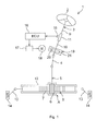
- FIG. 1 is a schematic view that shows the schematic configuration of an electric power steering system 1 that includes a worm reducer 19 according to an embodiment of the invention.
- the electric power steering system 1 includes a steering shaft 3, a pinion shaft 5 and a rack bar 8.
- the steering shaft 3 is coupled to a steering member 2 such as a steering wheel.
- the pinion shaft 5 is coupled to the steering shaft 3 via an intermediate shaft 4.
- the rack bar 8 has a rack 7 that is in mesh with a pinion 6 formed in the pinion shaft 5, and serves as a steered shaft that extends in the lateral direction of an automobile.
- the pinion shaft 5 and the rack bar 8 constitute a rack-and-pinion mechanism A that serves as a steering mechanism.
- the steering shaft 3 is formed of an input shaft 9 coupled to the steering member 2 and an output shaft 10 coupled to the pinion shaft 5.
- the input shaft 9 and the output shaft 10 are coupled to each other via a torsion bar 11 so as to be rotatable relative to each other on the same axis.
- the rack bar 8 is supported by a rack housing 12 via a plurality of bearings (not shown) so as to be able to make a linear reciprocating motion. End portions of the rack bar 8 protrude on respective sides of the rack housing 12, and steered wheels 14 are coupled to the respective end portions via tie rods 13 and knuckle arms (not shown).
- the steering shaft 3 rotates as the steering member 2 is operated.
- the rotation of the steering shaft 3 is converted into a linear reciprocating motion of the rack bar 8 in the lateral direction of a vehicle body via the pinion 6 and the rack 7.
- the steered wheels 14 are steered.
- a steering torque applied to the steering member 2 is detected by a torque sensor 15 on the basis of a relative rotational displacement between the input shaft 9 and the output shaft 10.
- the torque sensor 15 is provided near the steering shaft 3.
- the torque value detected by the torque sensor 15 is provided to an ECU 16.
- the ECU 16 executes, via a drive circuit 17, drive control of an electric motor 18 for assisting a steering operation, on the basis of the torque value, a vehicle speed provided from a vehicle speed sensor (not shown), and the like.
- the force transmitted to the output shaft 10 is transmitted to the rack bar 8 via the pinion shaft 5. In this way, a steering operation is assisted.
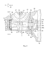
- FIG. 2 is a sectional view that shows the configuration of the worm reducer 19 provided in the electric power steering system 1 and portions near the worm reducer 19.
- the worm reducer 19 includes a worm shaft 20 and a worm wheel 21.
- the worm shaft 20 serves as a drive gear, and is rotated by the electric motor 18.
- the worm wheel 21 serves as a driven gear, and is in mesh with the worm shaft 20.
- Lubricant such as grease, is supplied in at least a meshing area MA between the worm shaft 20 and the worm wheel 21.
- the worm shaft 20 has a first end portion 22 and a second end portion 23.
- a worm 24 is formed at a middle portion between the first end portion 22 and the second end portion 23.
- the first end portion 22 is coaxially coupled to a rotary shaft 25 of the electric motor 18 via a coupling 26. With this configuration, the power output from the electric motor 18 is transmitted to the worm shaft 20.
- the coupling 26 includes a first member 26a, a second member 26b and an elastic member 26c.
- the first member 26a is coupled to the rotary shaft 25 of the electric motor 18 so as to be rotatable together with the rotary shaft 25.
- the second member 26b is coupled to the first end portion 22 of the worm shaft 20 so as to be rotatable together with the first end portion 22 of the worm shaft 20.
- the elastic member 26c couples the first member 26a and the second member 26b to each other such that torque is transmittable.
- the worm wheel 21 includes an annular metal member 27 and a synthetic resin member 28.
- the metal member 27 is connected to the output shaft 10 so as to be rotatable together with the output shaft 10.
- the synthetic resin member 28 surrounds the metal member 27, and teeth are formed on the outer periphery of the synthetic resin member 28.
- the metal member 27 is inserted in a die, for example, at the time of resin molding of the synthetic resin member 28.
- the worm wheel 21 is coupled to the output shaft 10 so as to be rotatable together with the output shaft 10 and axially immovable relative to the output shaft 10.
- the worm shaft 20 and the worm wheel 21 are accommodated in a gear housing 29.
- a first bearing 30 is arranged at the first end portion 22 of the worm shaft 20.
- a second bearing 31 is arranged at the second end portion 23 of the worm shaft 20.
- An inner ring 32 of the first bearing 30 is fitted to an outer periphery 22a of the first end portion 22 so as to be rotatable together with the first end portion 22 of the worm shaft 20.
- An outer ring 33 of the first bearing 30 is supported in a first bearing hole 34 formed in the gear housing 29. The outer ring 33 is held in an axial direction X1 of the worm shaft 20 by a step 35 formed at one end of the first bearing hole 34 and a threaded member 37 fitted to a threaded hole 36 contiguous with the first bearing hole 34.
- An inner ring 38 of the second bearing 31 is fitted to an outer periphery 23a of the second end portion 23 so as to be rotatable together with the second end portion 23 of the worm shaft 20.
- An outer ring 39 of the second bearing 31 is surrounded by a ring-shaped member 41 interposed between the inner wall of the gear housing 29, which defines a second bearing hole 40, and an outer periphery 39a of the outer ring 39.
- the ring-shaped member 41 is held by a pair of elastic members 42, 43 in a direction Y1 (hereinafter, referred to as "inter-axis distance adjustment direction Y1) in which an inter-axis distance D1 (which corresponds to the distance between a central axis C1 of the worm shaft 20 and a central axis C2 of the worm wheel 21) between the worm shaft 20 and the worm wheel 21.
- the elastic members 42, 43 constitute an elastic support mechanism 44 that urges the second end portion 23 of the worm shaft 20 toward a neutral position in the inter-axis distance adjustment direction Y1.
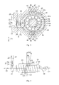
- FIG. 3 shows a sectional view taken along the line A-A in FIG. 2 .
- the second bearing hole 40 is formed of a cylindrical hole.
- the ring-shaped member 41 is formed of an elastically deformable member.
- An inner periphery 41 a of the ring-shaped member 41 forms an elongated hole that supports the second bearing 31 such that the second bearing 31 is movable in perpendicular directions Z1, Z2 that are perpendicular to both the inter-axis distance adjustment direction Y1 and the axial direction X1 of the worm shaft 20.
- the longitudinal direction of the elongated hole corresponds to the perpendicular directions Z1, Z2.
- the ring-shaped member 41 is in an annular shape under no-load conditions.
- the ring-shaped member 41 is held by the elastic members 42, 43 in the inter-axis distance adjustment direction Y1
- the ring-shaped member 41 becomes relatively short in the inter-axis distance adjustment direction Y2 and becomes relatively long in the perpendicular directions Z1, Z2.
- the elastic members 42, 43 both are elastically compressed in the inter-axis distance adjustment direction Y1, and elastically support the second end portion 23 of the worm shaft 20 at the neutral position in the inter-axis distance adjustment direction Y1 via the second bearing 31 by applying oppositely-directed elastic repulsions to the ring-shaped member 41.
- At least a sliding portion of the ring-shaped member 41 is preferably formed of a low-friction member in order to suppress friction resistance at the time when the second bearing 31 moves in the perpendicular directions Z1, Z2.
- the low-friction member used for the ring-shaped member 41 may be, for example, a resin member such as a fluororesin member, or a metal member such as a stainless steel member.
- Engaging protrusions 45, 46 are formed on an outer periphery 41b of the ring-shaped member 41 so as to protrude in opposite directions along the inter-axis distance adjustment direction Y1.
- the engaging protrusions 45, 46 serve as a pair of locking portions that lock the elastic members 42, 43, respectively.
- the elastic members 42, 43 have engaging holes 47, 48, respectively.
- the engaging holes 47, 48 serve as engaged portions that are engaged with the corresponding engaging protrusions 45, 46 of the ring-shaped member 41.
- Each of the engaging protrusions 45, 46 has a head 49 and a body 50 that connects the head 49 to the ring-shaped member 41.
- a retaining step 51 is formed between the head 49 and the body 50.
- the elastic members 42, 43 surround and hold the corresponding engaging protrusions 45, 46 in an elastically compressed state.
- the electric power steering system 1 includes an urging mechanism B.
- the urging mechanism B elastically urges the second end portion 23 of the worm shaft 20 in order to adjust a backlash between tooth flanks of the worm shaft 20 and worm wheel 21.
- the urging mechanism B is configured to adjust a backlash by elastically urging the second end portion 23 in the perpendicular direction Z1 that is perpendicular to the inter-axis distance adjustment direction Y1 in a state where increases and decreases in the inter-axis distance D1 between the worm shaft 20 and the worm wheel 21 are prevented.
- an urging member accommodating hole 52 is formed in the gear housing 29. The urging member accommodating hole 52 extends in the perpendicular direction Z1 so as to communicate with the second bearing hole 40.
- a pressing member retaining hole 53 is formed in the ring-shaped member 41.
- the pressing member retaining hole 53 extends in the perpendicular directions Z1, Z2.
- a pressing member 54 having, for example, a columnar shape, which is used to press the outer ring 39 of the second bearing 31 in the perpendicular direction Z1 is retained by one end of the urging member accommodating hole 52 and the pressing member retaining hole 53 so as to be slidable in the perpendicular directions Z1, Z2, in a state where the pressing member 54 lies astride one end of the urging member accommodating hole 52 and the pressing member retaining hole 53.
- a stopper 55 is fixedly fitted to the other end of the urging member accommodating hole 52.
- An urging member 56 which is formed of, for example, a compression coil spring, is accommodated in the urging member accommodating hole 52.
- the urging member 56 is interposed in a compressed state between the pressing member 54 and the stopper 55.
- the urging member 56 urges the second bearing 31 in the perpendicular direction Z1 via the pressing member 54.
- the perpendicular direction Z1 corresponds to a direction (that is, a lock direction) in which a lead angle ⁇ w of the worm shaft 20 becomes smaller than a lead angle ⁇ ww of the worm wheel 21.
- one tooth flank 201 (meshing-side tooth flank) of the worm shaft 20 is in mesh with a corresponding tooth flank 211 of the worm wheel 21, and the other tooth flank 202 of the worm shaft 20 is in mesh with a corresponding tooth flank 212 of the worm wheel 21.
- the urging mechanism B that elastically urges the second end portion 23 of the worm shaft 20 in order to adjust a backlash urges the second end portion 23 in the perpendicular direction Z1 that is perpendicular to the inter-axis distance adjustment direction Y1 in a state where increases and decreases in the inter-axis distance D1 are prevented.
- the perpendicular direction Z1 being the direction in which the lead angle ⁇ w of the worm shaft 20 becomes smaller than the lead angle ⁇ ww of the worm wheel 21, it is possible to keep the backlash at zero for a long period of time by compensating for wear of the tooth flanks of the worm shaft 20 and the tooth flanks of the worm wheel 21 and changes due to creep.
- the elastic support mechanism 44 that elastically supports the second end portion 23 of the worm shaft 20 at the neutral position in the inter-axis distance adjustment direction Y1. Therefore, in normal times, it is possible to prevent the worm shaft 20 from being displaced in the inter-axis distance adjustment direction Y1; whereas in the event of an emergency where an inverse input is received, for example, when the vehicle runs onto a curb, shock absorbing function is performed by the elastic support mechanism 44.
- the ring-shaped member 41 held by the elastic members 42, 43 elastically deforms, and the inner periphery 41a of the ring-shaped member 41 forms the elongated hole that extends in the longitudinal direction that corresponds to the perpendicular directions Z1, Z2. Therefore, the second bearing 31 is supported by the inner periphery 41a of the ring-shaped member 41 so as to be movable in the longitudinal direction (perpendicular directions Z1, Z2). Thus, it is no longer necessary to form the second bearing hole 40 of the gear housing 29 into an elongated shape. As a result, it is possible to reduce the manufacturing cost.
- the invention is not limited to the above-described embodiment.
- the inner ring 32 of the first bearing 30 and the inner ring 38 of the second bearing 31 may be loosely fitted to the corresponding end portions (the first end portion 22 and the second end portion 23) of the worm shaft 20, and then a pair of elastic members 59, 60 that elastically urge the worm shaft 20 in opposite directions along the axial direction X1 may be interposed between an end face of the inner ring 32 and a positioning step 57 of the worm shaft 20 and an end face of the inner ring 38 and a positioning step 58 of the worm shaft 20, respectively. That is, a backlash removal mechanism that removes a backlash by elastically urging the worm shaft 20 in the axial direction X1 may be added.
- the urging member 56 urges the second bearing 31 via the pressing member 54.
- the pressing member 54 may be omitted and the urging member 56 may directly press and urge the second bearing 31 (not shown).
- an elongated hole is formed by the ring-shaped member 41, by elastically deforming the ring-shaped member 41.
- the ring-shaped member 41 may be omitted and the second bearing hole 40 itself may be formed into an elongated shape (not shown).
Landscapes
- Engineering & Computer Science (AREA)
- General Engineering & Computer Science (AREA)
- Mechanical Engineering (AREA)
- Chemical & Material Sciences (AREA)
- Combustion & Propulsion (AREA)
- Transportation (AREA)
- Power Steering Mechanism (AREA)
- Gear Transmission (AREA)
- Gears, Cams (AREA)
Applications Claiming Priority (2)
| Application Number | Priority Date | Filing Date | Title |
|---|---|---|---|
| JP2011257993 | 2011-11-25 | ||
| JP2012196868A JP5999423B2 (ja) | 2011-11-25 | 2012-09-07 | 電動パワーステアリング装置 |
Publications (3)
| Publication Number | Publication Date |
|---|---|
| EP2597014A2 true EP2597014A2 (fr) | 2013-05-29 |
| EP2597014A3 EP2597014A3 (fr) | 2013-12-25 |
| EP2597014B1 EP2597014B1 (fr) | 2015-07-15 |
Family
ID=47290678
Family Applications (1)
| Application Number | Title | Priority Date | Filing Date |
|---|---|---|---|
| EP12193816.1A Not-in-force EP2597014B1 (fr) | 2011-11-25 | 2012-11-22 | Système de direction électrique |
Country Status (4)
| Country | Link |
|---|---|
| US (1) | US8813904B2 (fr) |
| EP (1) | EP2597014B1 (fr) |
| JP (1) | JP5999423B2 (fr) |
| CN (1) | CN103129603B (fr) |
Cited By (5)
| Publication number | Priority date | Publication date | Assignee | Title |
|---|---|---|---|---|
| WO2015176866A1 (fr) * | 2014-05-20 | 2015-11-26 | Robert Bosch Automotive Steering Gmbh | Mécanisme de direction |
| EP2993110A1 (fr) * | 2014-09-08 | 2016-03-09 | Jtekt Corporation | Réducteur de vitesse de vis sans fin |
| EP2966318A3 (fr) * | 2014-06-30 | 2017-08-23 | JTEKT Corporation | Réducteur de vitesse à vis sans fin et procédé de fabrication de roue à vis sans fin inclus dans un tel réducteur |
| CN108045429A (zh) * | 2017-12-08 | 2018-05-18 | 芜湖世特瑞转向系统有限公司 | 电动助力转向系统的减速器 |
| WO2021229175A1 (fr) * | 2020-05-13 | 2021-11-18 | Jtekt Europe | Réducteur de système à direction assistée électrique et système de direction assistée électrique |
Families Citing this family (21)
| Publication number | Priority date | Publication date | Assignee | Title |
|---|---|---|---|---|
| JP5618146B2 (ja) * | 2010-12-24 | 2014-11-05 | 株式会社ジェイテクト | 電動パワーステアリング装置 |
| WO2012173096A1 (fr) * | 2011-06-16 | 2012-12-20 | 日本精工株式会社 | Dispositif de direction assistée électrique |
| EP2842835A4 (fr) * | 2012-04-25 | 2016-04-06 | Jtekt Corp | Dispositif électrique de direction assistée |
| JP6020893B2 (ja) * | 2012-07-27 | 2016-11-02 | 株式会社ジェイテクト | 電動パワーステアリング装置 |
| JP6313969B2 (ja) * | 2013-12-25 | 2018-04-18 | Kyb株式会社 | パワーステアリング装置 |
| JP6362341B2 (ja) | 2014-01-31 | 2018-07-25 | キヤノン株式会社 | ウォーム減速機構およびそれを用いた雲台装置 |
| JP6129774B2 (ja) * | 2014-03-24 | 2017-05-17 | 株式会社ショーワ | パワーステアリング装置 |
| JP6118750B2 (ja) * | 2014-03-26 | 2017-04-19 | 株式会社ショーワ | ウォーム付勢構造体 |
| DE102014212133A1 (de) * | 2014-06-25 | 2015-12-31 | Robert Bosch Gmbh | Antriebseinheit |
| JP2016016784A (ja) * | 2014-07-09 | 2016-02-01 | 株式会社ジェイテクト | ウォーム減速機およびそれを用いた電動パワーステアリング装置 |
| JP6108358B2 (ja) * | 2014-07-23 | 2017-04-05 | 株式会社ショーワ | ウォーム付勢構造体 |
| JP2016055732A (ja) * | 2014-09-09 | 2016-04-21 | 日立オートモティブシステムズステアリング株式会社 | バックラッシュ調整機構及びこれを用いたパワーステアリング装置 |
| KR102254485B1 (ko) * | 2014-09-25 | 2021-05-21 | 현대모비스 주식회사 | 베어링 부시 |
| JP6167198B1 (ja) * | 2016-03-25 | 2017-07-19 | Kyb株式会社 | 電動パワーステアリング装置及び電動パワーステアリング装置の製造方法 |
| KR101957349B1 (ko) * | 2016-12-29 | 2019-06-19 | 이래에이엠에스 주식회사 | 전동식 파워 스티어링 시스템 |
| JP2018155301A (ja) * | 2017-03-16 | 2018-10-04 | 株式会社ジェイテクト | ウォーム減速機の製造方法、ウォーム減速機および電動パワーステアリング装置 |
| KR102033558B1 (ko) * | 2018-05-18 | 2019-10-17 | 주식회사 만도 | 전동식 동력 보조 조향장치의 감속기 |
| JP7133993B2 (ja) * | 2018-06-07 | 2022-09-09 | 株式会社ユーシン | 電動アクチュエータ |
| DE102018123960A1 (de) * | 2018-09-27 | 2020-04-02 | Trw Automotive Gmbh | Elektromotorisch unterstütztes Lenksystem sowie Verfahren zur Herstellung von Lenksystemen |
| KR102692481B1 (ko) * | 2019-02-12 | 2024-08-07 | 현대자동차주식회사 | 전동 조향장치의 노이즈 저감 장치 |
| KR102174602B1 (ko) * | 2019-05-14 | 2020-11-06 | 주식회사 만도 | 자동차의 조향장치 |
Citations (1)
| Publication number | Priority date | Publication date | Assignee | Title |
|---|---|---|---|---|
| JP2010116090A (ja) | 2008-11-14 | 2010-05-27 | Kayaba Ind Co Ltd | ウォーム減速機及び電動パワーステアリング装置 |
Family Cites Families (8)
| Publication number | Priority date | Publication date | Assignee | Title |
|---|---|---|---|---|
| JP3799236B2 (ja) * | 2001-01-22 | 2006-07-19 | 株式会社ジェイテクト | 電動式動力舵取装置 |
| IT950189B (it) * | 1972-03-15 | 1973-06-20 | Magneti Marelli Spa | Dispositivo per guidare e per ri prendere il gioco assiale delle viti dei riduttori a vite senza fine particolarmente per motori duttori di piccola potenza |
| JP3915610B2 (ja) * | 1997-05-29 | 2007-05-16 | 日本精工株式会社 | 電動式パワーステアリング装置 |
| JP2001108025A (ja) * | 1999-10-08 | 2001-04-20 | Koyo Seiko Co Ltd | 電動式舵取装置 |
| JP2005532511A (ja) * | 2002-07-08 | 2005-10-27 | ツェットエフ、レンクジステメ、ゲゼルシャフト、ミット、ベシュレンクテル、ハフツング | スラスト装置 |
| JP2006175891A (ja) * | 2004-12-20 | 2006-07-06 | Favess Co Ltd | 電動パワーステアリング装置 |
| KR100621347B1 (ko) * | 2005-09-20 | 2006-09-07 | 주식회사 만도 | 자동차의 전기식 동력 보조 조향 장치 |
| KR100816401B1 (ko) | 2006-07-05 | 2008-03-27 | 주식회사 만도 | 전동식 조향장치 |
-
2012
- 2012-09-07 JP JP2012196868A patent/JP5999423B2/ja not_active Expired - Fee Related
- 2012-11-19 US US13/680,375 patent/US8813904B2/en not_active Expired - Fee Related
- 2012-11-21 CN CN201210475356.1A patent/CN103129603B/zh not_active Expired - Fee Related
- 2012-11-22 EP EP12193816.1A patent/EP2597014B1/fr not_active Not-in-force
Patent Citations (1)
| Publication number | Priority date | Publication date | Assignee | Title |
|---|---|---|---|---|
| JP2010116090A (ja) | 2008-11-14 | 2010-05-27 | Kayaba Ind Co Ltd | ウォーム減速機及び電動パワーステアリング装置 |
Cited By (10)
| Publication number | Priority date | Publication date | Assignee | Title |
|---|---|---|---|---|
| WO2015176866A1 (fr) * | 2014-05-20 | 2015-11-26 | Robert Bosch Automotive Steering Gmbh | Mécanisme de direction |
| US10315687B2 (en) | 2014-05-20 | 2019-06-11 | Robert Bosch Automotive Steering Gmbh | Steering gear |
| EP2966318A3 (fr) * | 2014-06-30 | 2017-08-23 | JTEKT Corporation | Réducteur de vitesse à vis sans fin et procédé de fabrication de roue à vis sans fin inclus dans un tel réducteur |
| EP2993110A1 (fr) * | 2014-09-08 | 2016-03-09 | Jtekt Corporation | Réducteur de vitesse de vis sans fin |
| US9657811B2 (en) | 2014-09-08 | 2017-05-23 | Jtekt Corporation | Worm speed reducer |
| CN108045429A (zh) * | 2017-12-08 | 2018-05-18 | 芜湖世特瑞转向系统有限公司 | 电动助力转向系统的减速器 |
| CN108045429B (zh) * | 2017-12-08 | 2020-12-11 | 芜湖世特瑞转向系统有限公司 | 电动助力转向系统的减速器 |
| WO2021229175A1 (fr) * | 2020-05-13 | 2021-11-18 | Jtekt Europe | Réducteur de système à direction assistée électrique et système de direction assistée électrique |
| FR3110134A1 (fr) * | 2020-05-13 | 2021-11-19 | Jtekt Europe | Réducteur de système à direction assistée électrique et système de direction assistée électrique |
| US12448031B2 (en) | 2020-05-13 | 2025-10-21 | Jtekt Europe | Electric power steering system reducer and electric power steering system |
Also Published As
| Publication number | Publication date |
|---|---|
| JP5999423B2 (ja) | 2016-09-28 |
| EP2597014B1 (fr) | 2015-07-15 |
| EP2597014A3 (fr) | 2013-12-25 |
| CN103129603B (zh) | 2016-08-03 |
| JP2013129417A (ja) | 2013-07-04 |
| CN103129603A (zh) | 2013-06-05 |
| US8813904B2 (en) | 2014-08-26 |
| US20130133974A1 (en) | 2013-05-30 |
Similar Documents
| Publication | Publication Date | Title |
|---|---|---|
| EP2597014B1 (fr) | Système de direction électrique | |
| EP2559607B1 (fr) | Dispositif de direction électrique | |
| EP3088277B1 (fr) | Engrenage de réduction à vis sans fin et mécanisme de direction | |
| JP6020893B2 (ja) | 電動パワーステアリング装置 | |
| EP2713078B1 (fr) | Poulie entraînée en résine de nylon | |
| EP2966318B1 (fr) | Réducteur de vitesse à vis sans fin et procédé de fabrication de roue à vis sans fin inclus dans un tel réducteur | |
| EP3042826A1 (fr) | Système de direction fonctionnant à l'énergie électrique | |
| US20180201304A1 (en) | Dual-pinion electric power steering device | |
| EP3441645B1 (fr) | Réducteur de vis sans fin | |
| US8784253B2 (en) | Transmission ratio variable device | |
| EP2993110B1 (fr) | Réducteur de vitesse de vis sans fin | |
| EP3037324B1 (fr) | Dispositif a direction assistee electrique | |
| KR20170027170A (ko) | 자동차의 조향컬럼 | |
| EP2657105A1 (fr) | Direction électrique | |
| EP2966317A1 (fr) | Réducteur de vitesse à vis sans fin et système de direction assistée électrique utilisant celui-ci | |
| JP2002249056A (ja) | 電動パワーステアリング装置 | |
| EP3378732A1 (fr) | Dispositif de direction assistée et dispositif de direction le comprenant | |
| JP4234867B2 (ja) | 電動パワーステアリング装置 | |
| JP2012087881A (ja) | 動力伝達継手および電動パワーステアリング装置 | |
| EP1304504B1 (fr) | Dispositif de modification de vitesse à vis sans fin et direction assistée électrique | |
| JP4400369B2 (ja) | ピニオン・アシスト式電動パワーステアリング装置 | |
| JP2003004105A (ja) | 電動式パワーステアリング装置 | |
| JP2006082610A (ja) | 電動パワーステアリング装置 | |
| JP7705149B2 (ja) | 電動パワーステアリング装置およびその製造方法 | |
| JP2007216721A (ja) | 電動パワーステアリング装置 |
Legal Events
| Date | Code | Title | Description |
|---|---|---|---|
| PUAI | Public reference made under article 153(3) epc to a published international application that has entered the european phase |
Free format text: ORIGINAL CODE: 0009012 |
|
| AK | Designated contracting states |
Kind code of ref document: A2 Designated state(s): AL AT BE BG CH CY CZ DE DK EE ES FI FR GB GR HR HU IE IS IT LI LT LU LV MC MK MT NL NO PL PT RO RS SE SI SK SM TR |
|
| AX | Request for extension of the european patent |
Extension state: BA ME |
|
| PUAL | Search report despatched |
Free format text: ORIGINAL CODE: 0009013 |
|
| AK | Designated contracting states |
Kind code of ref document: A3 Designated state(s): AL AT BE BG CH CY CZ DE DK EE ES FI FR GB GR HR HU IE IS IT LI LT LU LV MC MK MT NL NO PL PT RO RS SE SI SK SM TR |
|
| AX | Request for extension of the european patent |
Extension state: BA ME |
|
| RIC1 | Information provided on ipc code assigned before grant |
Ipc: F16H 57/021 20120101ALN20131120BHEP Ipc: B62D 5/04 20060101AFI20131120BHEP Ipc: F16C 25/08 20060101ALI20131120BHEP Ipc: F16C 23/08 20060101ALI20131120BHEP |
|
| 17P | Request for examination filed |
Effective date: 20140618 |
|
| RBV | Designated contracting states (corrected) |
Designated state(s): AL AT BE BG CH CY CZ DE DK EE ES FI FR GB GR HR HU IE IS IT LI LT LU LV MC MK MT NL NO PL PT RO RS SE SI SK SM TR |
|
| GRAP | Despatch of communication of intention to grant a patent |
Free format text: ORIGINAL CODE: EPIDOSNIGR1 |
|
| RIC1 | Information provided on ipc code assigned before grant |
Ipc: B62D 5/04 20060101AFI20150119BHEP Ipc: F16C 23/08 20060101ALI20150119BHEP Ipc: F16C 25/08 20060101ALI20150119BHEP Ipc: F16H 57/021 20120101ALN20150119BHEP |
|
| INTG | Intention to grant announced |
Effective date: 20150202 |
|
| GRAS | Grant fee paid |
Free format text: ORIGINAL CODE: EPIDOSNIGR3 |
|
| GRAA | (expected) grant |
Free format text: ORIGINAL CODE: 0009210 |
|
| AK | Designated contracting states |
Kind code of ref document: B1 Designated state(s): AL AT BE BG CH CY CZ DE DK EE ES FI FR GB GR HR HU IE IS IT LI LT LU LV MC MK MT NL NO PL PT RO RS SE SI SK SM TR |
|
| REG | Reference to a national code |
Ref country code: CH Ref legal event code: EP Ref country code: GB Ref legal event code: FG4D |
|
| REG | Reference to a national code |
Ref country code: IE Ref legal event code: FG4D |
|
| REG | Reference to a national code |
Ref country code: AT Ref legal event code: REF Ref document number: 736624 Country of ref document: AT Kind code of ref document: T Effective date: 20150815 |
|
| REG | Reference to a national code |
Ref country code: DE Ref legal event code: R096 Ref document number: 602012008767 Country of ref document: DE |
|
| REG | Reference to a national code |
Ref country code: FR Ref legal event code: PLFP Year of fee payment: 4 |
|
| REG | Reference to a national code |
Ref country code: AT Ref legal event code: MK05 Ref document number: 736624 Country of ref document: AT Kind code of ref document: T Effective date: 20150715 |
|
| REG | Reference to a national code |
Ref country code: NL Ref legal event code: MP Effective date: 20150715 |
|
| REG | Reference to a national code |
Ref country code: LT Ref legal event code: MG4D |
|
| PG25 | Lapsed in a contracting state [announced via postgrant information from national office to epo] |
Ref country code: GR Free format text: LAPSE BECAUSE OF FAILURE TO SUBMIT A TRANSLATION OF THE DESCRIPTION OR TO PAY THE FEE WITHIN THE PRESCRIBED TIME-LIMIT Effective date: 20151016 Ref country code: LV Free format text: LAPSE BECAUSE OF FAILURE TO SUBMIT A TRANSLATION OF THE DESCRIPTION OR TO PAY THE FEE WITHIN THE PRESCRIBED TIME-LIMIT Effective date: 20150715 Ref country code: FI Free format text: LAPSE BECAUSE OF FAILURE TO SUBMIT A TRANSLATION OF THE DESCRIPTION OR TO PAY THE FEE WITHIN THE PRESCRIBED TIME-LIMIT Effective date: 20150715 Ref country code: LT Free format text: LAPSE BECAUSE OF FAILURE TO SUBMIT A TRANSLATION OF THE DESCRIPTION OR TO PAY THE FEE WITHIN THE PRESCRIBED TIME-LIMIT Effective date: 20150715 Ref country code: NO Free format text: LAPSE BECAUSE OF FAILURE TO SUBMIT A TRANSLATION OF THE DESCRIPTION OR TO PAY THE FEE WITHIN THE PRESCRIBED TIME-LIMIT Effective date: 20151015 |
|
| PG25 | Lapsed in a contracting state [announced via postgrant information from national office to epo] |
Ref country code: PL Free format text: LAPSE BECAUSE OF FAILURE TO SUBMIT A TRANSLATION OF THE DESCRIPTION OR TO PAY THE FEE WITHIN THE PRESCRIBED TIME-LIMIT Effective date: 20150715 Ref country code: ES Free format text: LAPSE BECAUSE OF FAILURE TO SUBMIT A TRANSLATION OF THE DESCRIPTION OR TO PAY THE FEE WITHIN THE PRESCRIBED TIME-LIMIT Effective date: 20150715 Ref country code: AT Free format text: LAPSE BECAUSE OF FAILURE TO SUBMIT A TRANSLATION OF THE DESCRIPTION OR TO PAY THE FEE WITHIN THE PRESCRIBED TIME-LIMIT Effective date: 20150715 Ref country code: RS Free format text: LAPSE BECAUSE OF FAILURE TO SUBMIT A TRANSLATION OF THE DESCRIPTION OR TO PAY THE FEE WITHIN THE PRESCRIBED TIME-LIMIT Effective date: 20150715 Ref country code: PT Free format text: LAPSE BECAUSE OF FAILURE TO SUBMIT A TRANSLATION OF THE DESCRIPTION OR TO PAY THE FEE WITHIN THE PRESCRIBED TIME-LIMIT Effective date: 20151116 Ref country code: SE Free format text: LAPSE BECAUSE OF FAILURE TO SUBMIT A TRANSLATION OF THE DESCRIPTION OR TO PAY THE FEE WITHIN THE PRESCRIBED TIME-LIMIT Effective date: 20150715 Ref country code: HR Free format text: LAPSE BECAUSE OF FAILURE TO SUBMIT A TRANSLATION OF THE DESCRIPTION OR TO PAY THE FEE WITHIN THE PRESCRIBED TIME-LIMIT Effective date: 20150715 |
|
| REG | Reference to a national code |
Ref country code: DE Ref legal event code: R097 Ref document number: 602012008767 Country of ref document: DE |
|
| PG25 | Lapsed in a contracting state [announced via postgrant information from national office to epo] |
Ref country code: EE Free format text: LAPSE BECAUSE OF FAILURE TO SUBMIT A TRANSLATION OF THE DESCRIPTION OR TO PAY THE FEE WITHIN THE PRESCRIBED TIME-LIMIT Effective date: 20150715 Ref country code: CZ Free format text: LAPSE BECAUSE OF FAILURE TO SUBMIT A TRANSLATION OF THE DESCRIPTION OR TO PAY THE FEE WITHIN THE PRESCRIBED TIME-LIMIT Effective date: 20150715 Ref country code: DK Free format text: LAPSE BECAUSE OF FAILURE TO SUBMIT A TRANSLATION OF THE DESCRIPTION OR TO PAY THE FEE WITHIN THE PRESCRIBED TIME-LIMIT Effective date: 20150715 Ref country code: SK Free format text: LAPSE BECAUSE OF FAILURE TO SUBMIT A TRANSLATION OF THE DESCRIPTION OR TO PAY THE FEE WITHIN THE PRESCRIBED TIME-LIMIT Effective date: 20150715 Ref country code: IT Free format text: LAPSE BECAUSE OF FAILURE TO SUBMIT A TRANSLATION OF THE DESCRIPTION OR TO PAY THE FEE WITHIN THE PRESCRIBED TIME-LIMIT Effective date: 20150715 |
|
| PLBE | No opposition filed within time limit |
Free format text: ORIGINAL CODE: 0009261 |
|
| STAA | Information on the status of an ep patent application or granted ep patent |
Free format text: STATUS: NO OPPOSITION FILED WITHIN TIME LIMIT |
|
| PG25 | Lapsed in a contracting state [announced via postgrant information from national office to epo] |
Ref country code: RO Free format text: LAPSE BECAUSE OF FAILURE TO SUBMIT A TRANSLATION OF THE DESCRIPTION OR TO PAY THE FEE WITHIN THE PRESCRIBED TIME-LIMIT Effective date: 20150715 |
|
| 26N | No opposition filed |
Effective date: 20160418 |
|
| PG25 | Lapsed in a contracting state [announced via postgrant information from national office to epo] |
Ref country code: LU Free format text: LAPSE BECAUSE OF FAILURE TO SUBMIT A TRANSLATION OF THE DESCRIPTION OR TO PAY THE FEE WITHIN THE PRESCRIBED TIME-LIMIT Effective date: 20151122 Ref country code: IS Free format text: LAPSE BECAUSE OF FAILURE TO SUBMIT A TRANSLATION OF THE DESCRIPTION OR TO PAY THE FEE WITHIN THE PRESCRIBED TIME-LIMIT Effective date: 20150715 Ref country code: MC Free format text: LAPSE BECAUSE OF FAILURE TO SUBMIT A TRANSLATION OF THE DESCRIPTION OR TO PAY THE FEE WITHIN THE PRESCRIBED TIME-LIMIT Effective date: 20150715 |
|
| REG | Reference to a national code |
Ref country code: CH Ref legal event code: PL |
|
| PG25 | Lapsed in a contracting state [announced via postgrant information from national office to epo] |
Ref country code: CH Free format text: LAPSE BECAUSE OF NON-PAYMENT OF DUE FEES Effective date: 20151130 Ref country code: LI Free format text: LAPSE BECAUSE OF NON-PAYMENT OF DUE FEES Effective date: 20151130 |
|
| REG | Reference to a national code |
Ref country code: IE Ref legal event code: MM4A |
|
| PG25 | Lapsed in a contracting state [announced via postgrant information from national office to epo] |
Ref country code: SI Free format text: LAPSE BECAUSE OF FAILURE TO SUBMIT A TRANSLATION OF THE DESCRIPTION OR TO PAY THE FEE WITHIN THE PRESCRIBED TIME-LIMIT Effective date: 20150715 |
|
| REG | Reference to a national code |
Ref country code: FR Ref legal event code: PLFP Year of fee payment: 5 |
|
| PG25 | Lapsed in a contracting state [announced via postgrant information from national office to epo] |
Ref country code: IE Free format text: LAPSE BECAUSE OF NON-PAYMENT OF DUE FEES Effective date: 20151122 |
|
| PG25 | Lapsed in a contracting state [announced via postgrant information from national office to epo] |
Ref country code: BE Free format text: LAPSE BECAUSE OF FAILURE TO SUBMIT A TRANSLATION OF THE DESCRIPTION OR TO PAY THE FEE WITHIN THE PRESCRIBED TIME-LIMIT Effective date: 20150715 |
|
| PG25 | Lapsed in a contracting state [announced via postgrant information from national office to epo] |
Ref country code: BG Free format text: LAPSE BECAUSE OF FAILURE TO SUBMIT A TRANSLATION OF THE DESCRIPTION OR TO PAY THE FEE WITHIN THE PRESCRIBED TIME-LIMIT Effective date: 20150715 Ref country code: SM Free format text: LAPSE BECAUSE OF FAILURE TO SUBMIT A TRANSLATION OF THE DESCRIPTION OR TO PAY THE FEE WITHIN THE PRESCRIBED TIME-LIMIT Effective date: 20150715 Ref country code: HU Free format text: LAPSE BECAUSE OF FAILURE TO SUBMIT A TRANSLATION OF THE DESCRIPTION OR TO PAY THE FEE WITHIN THE PRESCRIBED TIME-LIMIT; INVALID AB INITIO Effective date: 20121122 |
|
| PG25 | Lapsed in a contracting state [announced via postgrant information from national office to epo] |
Ref country code: NL Free format text: LAPSE BECAUSE OF FAILURE TO SUBMIT A TRANSLATION OF THE DESCRIPTION OR TO PAY THE FEE WITHIN THE PRESCRIBED TIME-LIMIT Effective date: 20150715 Ref country code: CY Free format text: LAPSE BECAUSE OF FAILURE TO SUBMIT A TRANSLATION OF THE DESCRIPTION OR TO PAY THE FEE WITHIN THE PRESCRIBED TIME-LIMIT Effective date: 20150715 |
|
| GBPC | Gb: european patent ceased through non-payment of renewal fee |
Effective date: 20161122 |
|
| PG25 | Lapsed in a contracting state [announced via postgrant information from national office to epo] |
Ref country code: MT Free format text: LAPSE BECAUSE OF FAILURE TO SUBMIT A TRANSLATION OF THE DESCRIPTION OR TO PAY THE FEE WITHIN THE PRESCRIBED TIME-LIMIT Effective date: 20150715 |
|
| REG | Reference to a national code |
Ref country code: FR Ref legal event code: PLFP Year of fee payment: 6 |
|
| PG25 | Lapsed in a contracting state [announced via postgrant information from national office to epo] |
Ref country code: GB Free format text: LAPSE BECAUSE OF NON-PAYMENT OF DUE FEES Effective date: 20161122 |
|
| PG25 | Lapsed in a contracting state [announced via postgrant information from national office to epo] |
Ref country code: TR Free format text: LAPSE BECAUSE OF FAILURE TO SUBMIT A TRANSLATION OF THE DESCRIPTION OR TO PAY THE FEE WITHIN THE PRESCRIBED TIME-LIMIT Effective date: 20150715 Ref country code: MK Free format text: LAPSE BECAUSE OF FAILURE TO SUBMIT A TRANSLATION OF THE DESCRIPTION OR TO PAY THE FEE WITHIN THE PRESCRIBED TIME-LIMIT Effective date: 20150715 |
|
| REG | Reference to a national code |
Ref country code: FR Ref legal event code: PLFP Year of fee payment: 7 |
|
| PG25 | Lapsed in a contracting state [announced via postgrant information from national office to epo] |
Ref country code: AL Free format text: LAPSE BECAUSE OF FAILURE TO SUBMIT A TRANSLATION OF THE DESCRIPTION OR TO PAY THE FEE WITHIN THE PRESCRIBED TIME-LIMIT Effective date: 20150715 |
|
| PGFP | Annual fee paid to national office [announced via postgrant information from national office to epo] |
Ref country code: DE Payment date: 20181106 Year of fee payment: 7 |
|
| PGFP | Annual fee paid to national office [announced via postgrant information from national office to epo] |
Ref country code: FR Payment date: 20181011 Year of fee payment: 7 |
|
| REG | Reference to a national code |
Ref country code: DE Ref legal event code: R119 Ref document number: 602012008767 Country of ref document: DE |
|
| PG25 | Lapsed in a contracting state [announced via postgrant information from national office to epo] |
Ref country code: FR Free format text: LAPSE BECAUSE OF NON-PAYMENT OF DUE FEES Effective date: 20191130 Ref country code: DE Free format text: LAPSE BECAUSE OF NON-PAYMENT OF DUE FEES Effective date: 20200603 |