EP2597232A2 - Dispositif de fermeture et de verrouillage avec un boîtier de serrure et une gâche - Google Patents
Dispositif de fermeture et de verrouillage avec un boîtier de serrure et une gâche Download PDFInfo
- Publication number
- EP2597232A2 EP2597232A2 EP12191188.7A EP12191188A EP2597232A2 EP 2597232 A2 EP2597232 A2 EP 2597232A2 EP 12191188 A EP12191188 A EP 12191188A EP 2597232 A2 EP2597232 A2 EP 2597232A2
- Authority
- EP
- European Patent Office
- Prior art keywords
- latch bolt
- door
- latch
- contact
- case
- Prior art date
- Legal status (The legal status is an assumption and is not a legal conclusion. Google has not performed a legal analysis and makes no representation as to the accuracy of the status listed.)
- Withdrawn
Links
- 230000008054 signal transmission Effects 0.000 claims abstract description 3
- 230000003287 optical effect Effects 0.000 claims description 5
- 238000012544 monitoring process Methods 0.000 claims 1
- 230000013011 mating Effects 0.000 description 3
- 230000005540 biological transmission Effects 0.000 description 2
- 239000011521 glass Substances 0.000 description 1
Images
Classifications
-
- E—FIXED CONSTRUCTIONS
- E05—LOCKS; KEYS; WINDOW OR DOOR FITTINGS; SAFES
- E05B—LOCKS; ACCESSORIES THEREFOR; HANDCUFFS
- E05B17/00—Accessories in connection with locks
- E05B17/22—Means for operating or controlling lock or fastening device accessories, i.e. other than the fastening members, e.g. switches, indicators
-
- E—FIXED CONSTRUCTIONS
- E05—LOCKS; KEYS; WINDOW OR DOOR FITTINGS; SAFES
- E05B—LOCKS; ACCESSORIES THEREFOR; HANDCUFFS
- E05B47/00—Operating or controlling locks or other fastening devices by electric or magnetic means
- E05B2047/0048—Circuits, feeding, monitoring
- E05B2047/0057—Feeding
- E05B2047/0059—Feeding by transfer between frame and wing
Definitions
- the invention relates to a locking and locking device with a lock case and a strike plate, wherein the lock case, for example, on a door, a window or the like and the strike plate is mounted on a frame for the door, the window or the like, and the lock case a trap or a latch bolt which engages in a receiving opening of the striking plate.
- Locking and locking devices are well known.
- the trap or the latch bolt is usually pulled with a pusher mechanically into the lock housing of the lock case in order to unlock and open the door.
- motorized locks are known in which the collection of the case or the latch bolt is no longer done by pressing the pusher or a key, but by means of an electric or electromagnetic drive.
- electrically lockable locks are known in which the collection of the case or the latch bolt is still done mechanically, the follower or the profile cylinder via an electrically driven clutch is switched on and off.
- sensors are provided which detect individual states of the lock and forward the data to components outside the lock.
- the latter locks as well as the motor locks and the electrically lockable locks must be energized in any case and measures must be taken to protect the signals e.g. transmitted by sensors.
- cables are usually used, which are routed from an energy source via the frame in the door leaf and from there into the lock case.
- the wiring is not only time consuming, but also has the disadvantage that the entire function of the system can be tested only with the commissioning of the finished door. Instead of cabling but also plunger contacts between the door and the door frame are known. However, these have the disadvantage that they are easy to manipulate, since they are in the door rebate.
- the door lock opposite fold is usually used for the wiring and the plunger contacts. It must then be routed through the door leaf through the wires.
- the invention has the object of developing a device of the type mentioned in such a way that it can be produced on the one hand with little effort, on the other hand is safe against manipulation.
- the agent on the case or on the latch bolt and in the receiving opening of the strike plate, the essential advantage is achieved that the agent is no longer exactly in the fold and thus the manipulation is much more difficult.
- the agent is located directly on the lock case, so that a wiring through the door leaf or around the door leaf around on the opposite, the hinges having side deleted.
- Another advantage is seen in the fact that existing systems can be easily converted by only the lock case and the strike plate are replaced.
- glass doors can be equipped, since, as already mentioned, no wiring on the door is required. Since the agent is on the lock case, the positions of the means on the trap or on the latch bolt and in the Strike according to the system. Furthermore, an existing infrastructure, such as wiring or the like, can be used in the door frame.
- a pre-assembly in the door and in the frame is not necessary, whereby the trades are independent.
- the means lie in a particularly secure area, namely in the receiving opening of the striking plate. This area is usually particularly secured against manipulation from the outside.
- the agent is designed as a contact. It is also possible to carry out the means without contact, in particular magnetic, electromagnetic or optical nature.
- a contacting is used in particular in the power supply or power transmission, wherein signals can be transmitted by radio, magenta or optically, especially in the infrared range.
- a particularly simple embodiment provides that the contact is designed as a pin or sliding contact or plug with socket.
- the contact is preferably movable, in particular pivotable and / or displaceable, arranged or is designed as a swiveling spring contact.
- the means may be designed as transmitters and receivers for acoustic, optical or magnetic signals.
- the receiver can not only receive the signals emitted by the opposite transmitter, but also, for example, signals that is output by a remote control, which is operated by an operator.
- the inventive device is at This embodiment is powered by first means and via second means data or signals are transmitted, which are output either from a locking system or from a remote control.
- the means are arranged at a suitable location on the trap or on the latch bolt, for example on the trailing edge. It is also possible to arrange the means alternatively or cumulatively at the top, the bottom, the front and / or the back of the trap or the latch bolt.
- the transmitter and receiver are preferably located on the bottom of the case or the latch bolt, so that they only face each other when the latch bolt is completely pushed out of the lock case and is in the receiving opening of the strike plate.
- an energy store is provided on the side of the lock case. This ensures that, even with the door open, in which no energy can be supplied via the contacts, the electrical components contained in the lock, such as controls and drives, are nevertheless supplied with energy, so that e.g. the latch bolt is held in the open position and extended again after a certain period of time.
- the energy spokes can be housed in the lock or in a cavity of the door leaf.
- a signal is sent via the contact, which is fed to a special receiver. This can only be done when the door is closed. For example, another signal is received only when the latch bolt is in the extended position.
- the signal can be routed from the lock to the strike plate or from the strike plate over the lock back to the strike plate.
- a code sequence is transmitted as a signal, which changes if necessary during each closing operation.
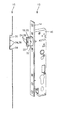
- the drawing shows a schematic representation of a strike plate 10 and in perspective view a lock case 12.
- the lock case 12 has a fixed to a cuff 14 housing 16, from which at least one trap 18 or a latch bolt 20 extends.
- the latch 18 or the latch bolt 20 has a latch bevel 22, on which two means 24 are provided, via which energy and / or signals can be transmitted.
- the means 24 are formed in the illustrated embodiment as mating contacts 26, which cooperate with means 24 in the strike plate 10, which are designed as contact pins 28.
- These contact pins 28 are located in the suggestively illustrated receiving opening 30, in which the latch bolt 20 retracts when the door assumes its closed position.
- the contact pins 28 are preferably resiliently and / or displaceably mounted in their longitudinal direction.
- About the contact pins 28 and the mating contacts 26 of the lock case 12 is supplied with power and signals and it
- the position of the latch bolt 20 and thus also the position of the door can be queried.
- a transmitter / receiver is arranged to the extended latch bolt 20, a transmitter / receiver in the strike plate 10 opposite, which is also located on the bottom 34 of the receiving opening 30.
- radio signals, optical signals or magnetic signals can be transmitted and received.
- a remote control of the trap latch 20 located receiver can be controlled directly.
Landscapes
- Lock And Its Accessories (AREA)
- Casings For Electric Apparatus (AREA)
Applications Claiming Priority (1)
| Application Number | Priority Date | Filing Date | Title |
|---|---|---|---|
| DE201120108332 DE202011108332U1 (de) | 2011-11-22 | 2011-11-22 | Schließ- und Verriegelungseinrichtung mit einem Schlosskasten und einem Schließblech |
Publications (2)
| Publication Number | Publication Date |
|---|---|
| EP2597232A2 true EP2597232A2 (fr) | 2013-05-29 |
| EP2597232A3 EP2597232A3 (fr) | 2014-10-29 |
Family
ID=45566601
Family Applications (1)
| Application Number | Title | Priority Date | Filing Date |
|---|---|---|---|
| EP12191188.7A Withdrawn EP2597232A3 (fr) | 2011-11-22 | 2012-11-05 | Dispositif de fermeture et de verrouillage avec un boîtier de serrure et une gâche |
Country Status (2)
| Country | Link |
|---|---|
| EP (1) | EP2597232A3 (fr) |
| DE (1) | DE202011108332U1 (fr) |
Families Citing this family (2)
| Publication number | Priority date | Publication date | Assignee | Title |
|---|---|---|---|---|
| DE202013001328U1 (de) | 2013-02-13 | 2013-03-15 | Kfv Karl Fliether Gmbh & Co. Kg | Kontaktanordnung |
| DE202017100475U1 (de) * | 2017-01-30 | 2018-05-03 | Sommer Antriebs- Und Funktechnik Gmbh | Tür |
Citations (2)
| Publication number | Priority date | Publication date | Assignee | Title |
|---|---|---|---|---|
| DE202004017953U1 (de) | 2004-11-18 | 2005-01-20 | Roto Frank Ag | Anordnung zur elektrischen Anspeisung von Verschlussantrieben |
| DE102008031155A1 (de) | 2008-07-03 | 2010-01-14 | Bonn, Georg, Dipl.-Ing. | Türe mit Druckkontaktleitungen |
Family Cites Families (11)
| Publication number | Priority date | Publication date | Assignee | Title |
|---|---|---|---|---|
| DE9012505U1 (de) * | 1990-08-31 | 1991-06-27 | Siemens AG, 80333 München | Elektronische Türschließvorrichtung |
| DE9012508U1 (de) * | 1990-08-31 | 1991-06-27 | Siemens Ag, 8000 Muenchen | Elektronische Türschließvorrichtung |
| DE4342315A1 (de) * | 1993-04-05 | 1994-10-06 | Erpelding Karl Heinz | Vorrichtung zur Aufnahme von Wertgegenständen o. dgl. |
| DE19738938B4 (de) * | 1996-09-16 | 2009-04-02 | Simonsvoss Technologies Ag | Schloß |
| CN2556322Y (zh) * | 2002-05-17 | 2003-06-18 | 张跃进 | 一种防盗门用电控防盗锁 |
| DE10246669A1 (de) * | 2002-10-07 | 2004-04-15 | Dorma Gmbh + Co. Kg | Türschloss |
| DE202005020914U1 (de) * | 2005-04-02 | 2006-11-23 | Kleinknecht Systemtechnik Gmbh | Griffstück zur Betätigung von verstellbaren Bauteilen |
| FR2890994B1 (fr) * | 2005-09-19 | 2007-11-23 | Deny Fontaine Soc Par Actions | Serrure electromecanique a fonctionnement conditionnel |
| DE202006014916U1 (de) * | 2006-09-25 | 2007-01-18 | Herold, Frank | Elektrische Alarmanlage für Türen und/oder Fenster |
| DE102010019261A1 (de) * | 2010-05-03 | 2011-11-03 | Heinz W. Perplies | Schließeinrichtung für eine Tür |
| DE202010007509U1 (de) * | 2010-06-02 | 2011-10-05 | MACO Vermögensverwaltung GmbH | Schloss und Tür, Fenster o.dgl. mit einem Schloss |
-
2011
- 2011-11-22 DE DE201120108332 patent/DE202011108332U1/de not_active Expired - Lifetime
-
2012
- 2012-11-05 EP EP12191188.7A patent/EP2597232A3/fr not_active Withdrawn
Patent Citations (2)
| Publication number | Priority date | Publication date | Assignee | Title |
|---|---|---|---|---|
| DE202004017953U1 (de) | 2004-11-18 | 2005-01-20 | Roto Frank Ag | Anordnung zur elektrischen Anspeisung von Verschlussantrieben |
| DE102008031155A1 (de) | 2008-07-03 | 2010-01-14 | Bonn, Georg, Dipl.-Ing. | Türe mit Druckkontaktleitungen |
Also Published As
| Publication number | Publication date |
|---|---|
| EP2597232A3 (fr) | 2014-10-29 |
| DE202011108332U1 (de) | 2012-01-05 |
Similar Documents
| Publication | Publication Date | Title |
|---|---|---|
| DE102005063378B4 (de) | Türverriegelungssystem | |
| WO2001094726A1 (fr) | Serrure a verrouillage automatique et systeme de fermeture comportant une telle serrure | |
| DE102016125888A1 (de) | Rahmen-Überwachungsvorrichtung für Fenster oder Türen und Fenster oder Tür mit Rahmen-Überwachungsvorrichtung | |
| EP1838941B1 (fr) | Dispositif pour determiner la position d'une poignee d'actionnement et/ou d'un vantail de fenetre ou de porte ou similaire | |
| DE202016009122U1 (de) | Schwenkantrieb zum Überführen eines kipp- und/oder schwenkbaren Fensterflügels in eine Lüftungsstellung | |
| DE102014111927B4 (de) | Schließmechanismus und Antriebsvorrichtung für ein Feuerschutztor sowie damit versehenes Feuerschutztor | |
| EP3795786B1 (fr) | Serrure de porte en verre à module radio autarcique | |
| EP2998487B1 (fr) | Serrure et systeme de fermeture electronique | |
| EP1229192A2 (fr) | Système de verrouillage pour porte | |
| EP2597232A2 (fr) | Dispositif de fermeture et de verrouillage avec un boîtier de serrure et une gâche | |
| EP3765688B1 (fr) | Ensemble ferrure pour un châssis de battant d'une fenêtre, fenêtre correspondante, procédé pour faire fonctionner un ensemble ferrure, procédé pour monter un ensemble ferrure et dispositif capteur | |
| DE102014104128B4 (de) | Zuhaltung | |
| EP2381055B1 (fr) | Serrure pour un élément de fermeture | |
| EP2765261A2 (fr) | Dispositif de fermeture d'un bâtiment | |
| EP3045623A1 (fr) | Dispositif de sécurisation de porte | |
| EP2362040B1 (fr) | Dispositif de fermeture | |
| DE20220993U1 (de) | Türschließsystem | |
| EP3165695A1 (fr) | Dispositif et procédé d'actionnement d'une poignée de porte | |
| DE102015104818A1 (de) | Verfahren zum Betreiben eines Türantriebs, Türantriebssteuerung, Türantrieb und Drehflügeltür | |
| DE102006042469B4 (de) | Schließanlage und Tür mit Schließanlage | |
| EP3568557A1 (fr) | Système d'entraînement de porte et procédé de fonctionnement associé | |
| EP2589729B1 (fr) | Poignée avec un émetteur de signal électrique pour l'actionnement d'une porte de garage sectionnelle latérale | |
| EP3032004B1 (fr) | Système de verrouillage pour une porte ou pour une fenêtre et procédé de fabrication d'un système de verrouillage | |
| AT17564U1 (de) | Möbelstück mit Öffner | |
| DE102008014548B4 (de) | Verriegelungsanordnung |
Legal Events
| Date | Code | Title | Description |
|---|---|---|---|
| PUAI | Public reference made under article 153(3) epc to a published international application that has entered the european phase |
Free format text: ORIGINAL CODE: 0009012 |
|
| AK | Designated contracting states |
Kind code of ref document: A2 Designated state(s): AL AT BE BG CH CY CZ DE DK EE ES FI FR GB GR HR HU IE IS IT LI LT LU LV MC MK MT NL NO PL PT RO RS SE SI SK SM TR |
|
| AX | Request for extension of the european patent |
Extension state: BA ME |
|
| PUAL | Search report despatched |
Free format text: ORIGINAL CODE: 0009013 |
|
| AK | Designated contracting states |
Kind code of ref document: A3 Designated state(s): AL AT BE BG CH CY CZ DE DK EE ES FI FR GB GR HR HU IE IS IT LI LT LU LV MC MK MT NL NO PL PT RO RS SE SI SK SM TR |
|
| AX | Request for extension of the european patent |
Extension state: BA ME |
|
| RIC1 | Information provided on ipc code assigned before grant |
Ipc: E05B 17/22 20060101AFI20140923BHEP Ipc: E05B 47/00 20060101ALI20140923BHEP |
|
| STAA | Information on the status of an ep patent application or granted ep patent |
Free format text: STATUS: THE APPLICATION IS DEEMED TO BE WITHDRAWN |
|
| 18D | Application deemed to be withdrawn |
Effective date: 20150430 |