EP2597298A2 - Bougie d'allumage laser - Google Patents
Bougie d'allumage laser Download PDFInfo
- Publication number
- EP2597298A2 EP2597298A2 EP12007723.5A EP12007723A EP2597298A2 EP 2597298 A2 EP2597298 A2 EP 2597298A2 EP 12007723 A EP12007723 A EP 12007723A EP 2597298 A2 EP2597298 A2 EP 2597298A2
- Authority
- EP
- European Patent Office
- Prior art keywords
- spark plug
- laser spark
- housing
- pressure sensor
- sleeve
- Prior art date
- Legal status (The legal status is an assumption and is not a legal conclusion. Google has not performed a legal analysis and makes no representation as to the accuracy of the status listed.)
- Withdrawn
Links
- 238000002485 combustion reaction Methods 0.000 claims abstract description 16
- 238000007789 sealing Methods 0.000 claims abstract description 14
- 230000003287 optical effect Effects 0.000 claims description 7
- 238000005259 measurement Methods 0.000 description 2
- 230000005855 radiation Effects 0.000 description 2
- 238000009530 blood pressure measurement Methods 0.000 description 1
- 230000006835 compression Effects 0.000 description 1
- 238000007906 compression Methods 0.000 description 1
- 238000001816 cooling Methods 0.000 description 1
- 230000001419 dependent effect Effects 0.000 description 1
- 238000001514 detection method Methods 0.000 description 1
- 238000002474 experimental method Methods 0.000 description 1
- 230000010354 integration Effects 0.000 description 1
- 238000000034 method Methods 0.000 description 1
- 238000012986 modification Methods 0.000 description 1
- 230000004048 modification Effects 0.000 description 1
Images

Classifications
-
- F—MECHANICAL ENGINEERING; LIGHTING; HEATING; WEAPONS; BLASTING
- F02—COMBUSTION ENGINES; HOT-GAS OR COMBUSTION-PRODUCT ENGINE PLANTS
- F02P—IGNITION, OTHER THAN COMPRESSION IGNITION, FOR INTERNAL-COMBUSTION ENGINES; TESTING OF IGNITION TIMING IN COMPRESSION-IGNITION ENGINES
- F02P23/00—Other ignition
- F02P23/04—Other physical ignition means, e.g. using laser rays
-
- G—PHYSICS
- G01—MEASURING; TESTING
- G01L—MEASURING FORCE, STRESS, TORQUE, WORK, MECHANICAL POWER, MECHANICAL EFFICIENCY, OR FLUID PRESSURE
- G01L23/00—Devices or apparatus for measuring or indicating or recording rapid changes, such as oscillations, in the pressure of steam, gas, or liquid; Indicators for determining work or energy of steam, internal-combustion, or other fluid-pressure engines from the condition of the working fluid
- G01L23/08—Devices or apparatus for measuring or indicating or recording rapid changes, such as oscillations, in the pressure of steam, gas, or liquid; Indicators for determining work or energy of steam, internal-combustion, or other fluid-pressure engines from the condition of the working fluid operated electrically
- G01L23/18—Devices or apparatus for measuring or indicating or recording rapid changes, such as oscillations, in the pressure of steam, gas, or liquid; Indicators for determining work or energy of steam, internal-combustion, or other fluid-pressure engines from the condition of the working fluid operated electrically by resistance strain gauges
-
- F—MECHANICAL ENGINEERING; LIGHTING; HEATING; WEAPONS; BLASTING
- F02—COMBUSTION ENGINES; HOT-GAS OR COMBUSTION-PRODUCT ENGINE PLANTS
- F02D—CONTROLLING COMBUSTION ENGINES
- F02D35/00—Controlling engines, dependent on conditions exterior or interior to engines, not otherwise provided for
- F02D35/02—Controlling engines, dependent on conditions exterior or interior to engines, not otherwise provided for on interior conditions
- F02D35/023—Controlling engines, dependent on conditions exterior or interior to engines, not otherwise provided for on interior conditions by determining the cylinder pressure
Definitions
- the present invention relates to a laser spark plug having the features of the preamble of claim 1.
- Modern internal combustion engines in particular gas Otto engines, with a power class above about 2000 kW increasingly require measures to detect and control the combustion processes within the individual cylinders in order to apply timely and cylinder-specific control or control methods can.
- Both the laser ignition and the cylinder pressure measurement are cost-intensive and technologically demanding, both measures require access to the combustion chamber.
- a generic laser spark plug goes out of the DE 10 2009 029 428 A1
- the at least one pressure sensor taught in this document makes it possible to measure the cylinder pressure during operation of the internal combustion engine.
- the integration of the pressure sensor makes it possible to manage with a single combustion chamber access for the laser ignition and the determination of the cylinder pressure.
- the object of the invention is to increase the measurement accuracy while retaining the advantage of a single combustion chamber access.
- FIG. 1 shows a laser spark plug according to the invention 1 in the assembled state in the cylinder block 11 of an otherwise not shown internal combustion engine, which is preferably designed as (in particular stationary) gas Otto engine, in particular in a power class above about 2000 kW.
- the laser spark plug 1 has a housing 2 with different sections: starting from the vicinity of the combustion chamber (not shown) extends a component 20, which on the one hand acts as a holder for an optical window 10 and on the other hand has the sealing seat 4 of the laser spark plug 1. This is followed by a trained as a sleeve 6 section of the housing 2.
- the sleeve 6 has a cross-sectional tapering 8 in which a pressure sensor 5 designed as strain gauges is arranged.
- the cross-sectional taper 8 serves to reinforce the measurement signal of the pressure sensor 5 which occurs as a consequence of the compression of the sleeve 6 induced by the cylinder pressure.
- the sleeve 6 is connected to an upper portion 22 of the housing 2.
- the section 22 serves on the one hand as a receptacle for the optical assembly of the laser spark plug 1 and on the other hand connected to a mounting portion 3 of the housing 2 of the laser spark plug 1.
- the attachment portion 3 of the housing 2 of the laser spark plug 1 is formed in this embodiment on a separate component 21, which with the viewed in the axial extent of the laser spark plug, the component 20 having the sealing seat 4 is connected only via the sleeve 6. All axial forces occurring between the attachment section 3 and the sealing seat 4 therefore extend over the sleeve 6 and can be detected by the pressure sensor 5.
- the optical assembly is known per se from the prior art and therefore need not be described in detail.
- a pump laser 16 is supplied with electrical energy.
- the radiation of the pump laser 16 is fed to an ignition laser 17.
- the radiation of the ignition laser 17 is collimated by a lens 18 and coupled via the here formed as a converging lens optical window 10 into the combustion chamber.
- a sealing ring 19 is inserted.
- the laser spark plug 1 shown here is formed with a long housing 2, wherein the length of the laser spark plug 1 at least five times the diameter of the sleeve 6 corresponds. Both the mounting portion 3 and the optical assembly is in the assembled state of the laser spark plug 1 as far as possible away from the combustion chamber, which is positive with respect to the temperature load.
- the pressure sensor 5 can have at least one strain gauge or can be configured only as such. When using strain gauges, make sure that the temperature does not rise above approx. 120 ° C. This is in the version of FIG. 1 on the one hand by the positioning of the pressure sensor 5 relatively far away from the combustion chamber and on the other hand ensured by the proximity of the cooling chambers 12 of the cylinder head 11.
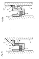
- the laser spark plug 1 has a further component in the form of a sleeve 7 designed as a clamping sleeve.
- the alleged disadvantage of an additionally required component is compensated for in this variant in that the temperature at the pressure sensor 5 can be kept below about 100 ° C and the DehnmessstMails the pressure sensor 5 is in a protected position. This applies equally to the embodiment of the FIG. 2b ,
- FIGS. 2a and 2b In the variants of FIGS. 2a and 2b is the housing 2 of the laser spark plug 1, which is connected to the cylinder head 11 via a threaded sleeve 9, pressed by the trained as a clamping sleeve sleeve 7 in the direction of the combustion chamber.
- the two FIGS. 2a and 2b drawn weld 14 is not essential.
- the in the FIGS. 2a and 2b unrecognizable details of the laser spark plug 1 are as in FIG. 1 educated.
- the strain gauge can simply be glued to the housing 2 of the laser spark plug 1 or to the sleeve 7 designed as a clamping sleeve or to another suitable component.
- the power or signal line for the pressure sensor 5 can be performed within or just outside the housing 2 of the laser spark plug 1. It may be provided with those for the pressure sensor 5 in a common cable management a combination of lines for the laser ignition.
Landscapes
- Engineering & Computer Science (AREA)
- Physics & Mathematics (AREA)
- Chemical & Material Sciences (AREA)
- Combustion & Propulsion (AREA)
- Optics & Photonics (AREA)
- Mechanical Engineering (AREA)
- General Engineering & Computer Science (AREA)
- General Physics & Mathematics (AREA)
- Measuring Fluid Pressure (AREA)
Applications Claiming Priority (1)
| Application Number | Priority Date | Filing Date | Title |
|---|---|---|---|
| AT17252011A AT512253B1 (de) | 2011-11-22 | 2011-11-22 | Laserzündkerze |
Publications (2)
| Publication Number | Publication Date |
|---|---|
| EP2597298A2 true EP2597298A2 (fr) | 2013-05-29 |
| EP2597298A3 EP2597298A3 (fr) | 2016-04-20 |
Family
ID=47290530
Family Applications (1)
| Application Number | Title | Priority Date | Filing Date |
|---|---|---|---|
| EP12007723.5A Withdrawn EP2597298A3 (fr) | 2011-11-22 | 2012-11-15 | Bougie d'allumage laser |
Country Status (2)
| Country | Link |
|---|---|
| EP (1) | EP2597298A3 (fr) |
| AT (1) | AT512253B1 (fr) |
Families Citing this family (1)
| Publication number | Priority date | Publication date | Assignee | Title |
|---|---|---|---|---|
| US12410760B2 (en) | 2023-11-29 | 2025-09-09 | Cummins Power Generation Inc. | Control system for an internal combustion engine, internal combustion engine system, and method for controlling internal combustion engine |
Citations (1)
| Publication number | Priority date | Publication date | Assignee | Title |
|---|---|---|---|---|
| DE102009029428A1 (de) | 2009-09-14 | 2011-03-24 | Robert Bosch Gmbh | Laserzündkerze |
Family Cites Families (7)
| Publication number | Priority date | Publication date | Assignee | Title |
|---|---|---|---|---|
| GB2304812A (en) * | 1995-08-26 | 1997-03-26 | Ford Motor Co | Pressure sensing spark plug |
| US6204594B1 (en) * | 1998-06-12 | 2001-03-20 | Cooper Automotive Products, Inc. | Spark plug with pressure sensor |
| US6799451B2 (en) * | 2001-03-05 | 2004-10-05 | Delphi Technologies, Inc. | Spark generating apparatus having strain gage cylinder pressure measurement feature |
| DE10341335B4 (de) * | 2003-09-08 | 2013-07-11 | Continental Automotive Gmbh | Anordnung mit Einspritzventil und einer Hülse als Druckübertragungsmittel |
| FR2925777B1 (fr) * | 2007-12-21 | 2010-09-17 | Siemens Vdo Automotive | Bougie d'allumage a capteur de pression integre pour moteur a combustion interne |
| AT506343B1 (de) * | 2008-02-07 | 2010-12-15 | Ge Jenbacher Gmbh & Co Ohg | Laserzündeinrichtung |
| JP5237237B2 (ja) * | 2009-10-16 | 2013-07-17 | 日本特殊陶業株式会社 | スパークプラグ |
-
2011
- 2011-11-22 AT AT17252011A patent/AT512253B1/de not_active IP Right Cessation
-
2012
- 2012-11-15 EP EP12007723.5A patent/EP2597298A3/fr not_active Withdrawn
Patent Citations (1)
| Publication number | Priority date | Publication date | Assignee | Title |
|---|---|---|---|---|
| DE102009029428A1 (de) | 2009-09-14 | 2011-03-24 | Robert Bosch Gmbh | Laserzündkerze |
Also Published As
| Publication number | Publication date |
|---|---|
| AT512253B1 (de) | 2013-11-15 |
| AT512253A1 (de) | 2013-06-15 |
| EP2597298A3 (fr) | 2016-04-20 |
Similar Documents
| Publication | Publication Date | Title |
|---|---|---|
| DE19680912C2 (de) | Vorrichtung und Verfahren zum Detektieren des Zylinderdrucks eines Dieselmotors | |
| DE102006027710B4 (de) | Verfahren und Vorrichtung zur indirekten Messung eines Motorzylinderdrucks | |
| DE102004011098A1 (de) | Vorrichtung zur Erfassung des Brennraumdrucks bei einer Brennkraftmaschine | |
| DE102016010657A1 (de) | Spannvorrichtung mit einer Sensoranordnung | |
| DE10317377A1 (de) | Klopferfassungsvorrichtung für eine Verbrennungskraftmaschine | |
| WO2009067833A2 (fr) | Composant pour mesurer une force ou une pression et capteur comprenant un tel composant | |
| DE102016113196A1 (de) | Digitale Gewindeeingriffsmessung | |
| EP0283524B1 (fr) | Méthode et dispositif pour la mesure des pressions dans des corps tubulaires | |
| DE102017004375A1 (de) | Spritzgiessmaschine | |
| DE19819301C1 (de) | Verfahren und Vorrichtung zum Prüfen der Vorspannkraft von Schraubverbindungen | |
| AT512253B1 (de) | Laserzündkerze | |
| DE2949100A1 (de) | Einrichtung zum festhalten einer in einer kraftstoffeinspritzpumpe fuer brennkraftmaschinen angeordneten antriebswelle | |
| DE102016121611A1 (de) | Drucksensor | |
| EP1498599A1 (fr) | Joint de culasse | |
| DE102015109063B4 (de) | Temperatursensor und Verfahren zur Herstellung desselben | |
| DE10302352A1 (de) | Kraftaufnehmer zum Messen von Achskräften | |
| EP1524422B1 (fr) | Procédé pour surveiller la pression d'un cylindre | |
| EP0671618B1 (fr) | Moteurs et compresseurs à piston avec système de surveillance | |
| DE202008007403U1 (de) | Halterung für elektronische Wegmesssonden | |
| DE102006034369A1 (de) | Verfahren zum Betrieb eines Verbrennungsmotors im Schadensfall und Einrichtung zur Durchführung des Verfahrens | |
| DE102006053806B4 (de) | Brennkraftmaschine | |
| DE102014100383B4 (de) | Schraubenbefestigungskomponente und deren Herstellungsverfahren | |
| DE102005025115A1 (de) | Integrierter Brennraumdrucksensor | |
| DE19723804C2 (de) | Vorrichtung zur Ermittlung des Druckes im Arbeitsraum von Hubkolbenmaschinen | |
| DE10351640B4 (de) | Verfahren zur Kontrolle von bruchgetrennten Bauteilen hinsichlich der Qualität der Trennung |
Legal Events
| Date | Code | Title | Description |
|---|---|---|---|
| PUAI | Public reference made under article 153(3) epc to a published international application that has entered the european phase |
Free format text: ORIGINAL CODE: 0009012 |
|
| AK | Designated contracting states |
Kind code of ref document: A2 Designated state(s): AL AT BE BG CH CY CZ DE DK EE ES FI FR GB GR HR HU IE IS IT LI LT LU LV MC MK MT NL NO PL PT RO RS SE SI SK SM TR |
|
| AX | Request for extension of the european patent |
Extension state: BA ME |
|
| PUAL | Search report despatched |
Free format text: ORIGINAL CODE: 0009013 |
|
| AK | Designated contracting states |
Kind code of ref document: A3 Designated state(s): AL AT BE BG CH CY CZ DE DK EE ES FI FR GB GR HR HU IE IS IT LI LT LU LV MC MK MT NL NO PL PT RO RS SE SI SK SM TR |
|
| AX | Request for extension of the european patent |
Extension state: BA ME |
|
| RIC1 | Information provided on ipc code assigned before grant |
Ipc: F02D 35/02 20060101ALI20160314BHEP Ipc: G01L 23/22 20060101ALI20160314BHEP Ipc: F02P 23/04 20060101AFI20160314BHEP |
|
| STAA | Information on the status of an ep patent application or granted ep patent |
Free format text: STATUS: THE APPLICATION HAS BEEN PUBLISHED |
|
| STAA | Information on the status of an ep patent application or granted ep patent |
Free format text: STATUS: THE APPLICATION IS DEEMED TO BE WITHDRAWN |
|
| 18D | Application deemed to be withdrawn |
Effective date: 20161021 |