EP2597301B1 - Windmühle und Nabenversiegelungsvorrichtung dafür - Google Patents
Windmühle und Nabenversiegelungsvorrichtung dafür Download PDFInfo
- Publication number
- EP2597301B1 EP2597301B1 EP12183965.8A EP12183965A EP2597301B1 EP 2597301 B1 EP2597301 B1 EP 2597301B1 EP 12183965 A EP12183965 A EP 12183965A EP 2597301 B1 EP2597301 B1 EP 2597301B1
- Authority
- EP
- European Patent Office
- Prior art keywords
- sealing
- coupler
- ring
- support
- sealing ring
- Prior art date
- Legal status (The legal status is an assumption and is not a legal conclusion. Google has not performed a legal analysis and makes no representation as to the accuracy of the status listed.)
- Not-in-force
Links
Images


Classifications
-
- F—MECHANICAL ENGINEERING; LIGHTING; HEATING; WEAPONS; BLASTING
- F03—MACHINES OR ENGINES FOR LIQUIDS; WIND, SPRING, OR WEIGHT MOTORS; PRODUCING MECHANICAL POWER OR A REACTIVE PROPULSIVE THRUST, NOT OTHERWISE PROVIDED FOR
- F03D—WIND MOTORS
- F03D1/00—Wind motors with rotation axis substantially parallel to the air flow entering the rotor
- F03D1/06—Rotors
- F03D1/065—Rotors characterised by their construction elements
- F03D1/0658—Arrangements for fixing wind-engaging parts to a hub
-
- F—MECHANICAL ENGINEERING; LIGHTING; HEATING; WEAPONS; BLASTING
- F03—MACHINES OR ENGINES FOR LIQUIDS; WIND, SPRING, OR WEIGHT MOTORS; PRODUCING MECHANICAL POWER OR A REACTIVE PROPULSIVE THRUST, NOT OTHERWISE PROVIDED FOR
- F03D—WIND MOTORS
- F03D80/00—Details, components or accessories not provided for in groups F03D1/00 - F03D17/00
-
- F—MECHANICAL ENGINEERING; LIGHTING; HEATING; WEAPONS; BLASTING
- F16—ENGINEERING ELEMENTS AND UNITS; GENERAL MEASURES FOR PRODUCING AND MAINTAINING EFFECTIVE FUNCTIONING OF MACHINES OR INSTALLATIONS; THERMAL INSULATION IN GENERAL
- F16C—SHAFTS; FLEXIBLE SHAFTS; ELEMENTS OR CRANKSHAFT MECHANISMS; ROTARY BODIES OTHER THAN GEARING ELEMENTS; BEARINGS
- F16C33/00—Parts of bearings; Special methods for making bearings or parts thereof
- F16C33/72—Sealings
- F16C33/76—Sealings of ball or roller bearings
- F16C33/768—Sealings of ball or roller bearings between relatively stationary parts, i.e. static seals
-
- F—MECHANICAL ENGINEERING; LIGHTING; HEATING; WEAPONS; BLASTING
- F16—ENGINEERING ELEMENTS AND UNITS; GENERAL MEASURES FOR PRODUCING AND MAINTAINING EFFECTIVE FUNCTIONING OF MACHINES OR INSTALLATIONS; THERMAL INSULATION IN GENERAL
- F16C—SHAFTS; FLEXIBLE SHAFTS; ELEMENTS OR CRANKSHAFT MECHANISMS; ROTARY BODIES OTHER THAN GEARING ELEMENTS; BEARINGS
- F16C33/00—Parts of bearings; Special methods for making bearings or parts thereof
- F16C33/72—Sealings
- F16C33/76—Sealings of ball or roller bearings
- F16C33/78—Sealings of ball or roller bearings with a diaphragm, disc, or ring, with or without resilient members
- F16C33/7836—Sealings of ball or roller bearings with a diaphragm, disc, or ring, with or without resilient members floating with respect to both races
-
- F—MECHANICAL ENGINEERING; LIGHTING; HEATING; WEAPONS; BLASTING
- F16—ENGINEERING ELEMENTS AND UNITS; GENERAL MEASURES FOR PRODUCING AND MAINTAINING EFFECTIVE FUNCTIONING OF MACHINES OR INSTALLATIONS; THERMAL INSULATION IN GENERAL
- F16C—SHAFTS; FLEXIBLE SHAFTS; ELEMENTS OR CRANKSHAFT MECHANISMS; ROTARY BODIES OTHER THAN GEARING ELEMENTS; BEARINGS
- F16C33/00—Parts of bearings; Special methods for making bearings or parts thereof
- F16C33/72—Sealings
- F16C33/76—Sealings of ball or roller bearings
- F16C33/78—Sealings of ball or roller bearings with a diaphragm, disc, or ring, with or without resilient members
- F16C33/7886—Sealings of ball or roller bearings with a diaphragm, disc, or ring, with or without resilient members mounted outside the gap between the inner and outer races, e.g. sealing rings mounted to an end face or outer surface of a race
-
- F—MECHANICAL ENGINEERING; LIGHTING; HEATING; WEAPONS; BLASTING
- F03—MACHINES OR ENGINES FOR LIQUIDS; WIND, SPRING, OR WEIGHT MOTORS; PRODUCING MECHANICAL POWER OR A REACTIVE PROPULSIVE THRUST, NOT OTHERWISE PROVIDED FOR
- F03D—WIND MOTORS
- F03D80/00—Details, components or accessories not provided for in groups F03D1/00 - F03D17/00
- F03D80/70—Bearing or lubricating arrangements
-
- F—MECHANICAL ENGINEERING; LIGHTING; HEATING; WEAPONS; BLASTING
- F05—INDEXING SCHEMES RELATING TO ENGINES OR PUMPS IN VARIOUS SUBCLASSES OF CLASSES F01-F04
- F05B—INDEXING SCHEME RELATING TO WIND, SPRING, WEIGHT, INERTIA OR LIKE MOTORS, TO MACHINES OR ENGINES FOR LIQUIDS COVERED BY SUBCLASSES F03B, F03D AND F03G
- F05B2240/00—Components
- F05B2240/20—Rotors
- F05B2240/21—Rotors for wind turbines
- F05B2240/221—Rotors for wind turbines with horizontal axis
-
- F—MECHANICAL ENGINEERING; LIGHTING; HEATING; WEAPONS; BLASTING
- F05—INDEXING SCHEMES RELATING TO ENGINES OR PUMPS IN VARIOUS SUBCLASSES OF CLASSES F01-F04
- F05B—INDEXING SCHEME RELATING TO WIND, SPRING, WEIGHT, INERTIA OR LIKE MOTORS, TO MACHINES OR ENGINES FOR LIQUIDS COVERED BY SUBCLASSES F03B, F03D AND F03G
- F05B2240/00—Components
- F05B2240/57—Seals
-
- F—MECHANICAL ENGINEERING; LIGHTING; HEATING; WEAPONS; BLASTING
- F16—ENGINEERING ELEMENTS AND UNITS; GENERAL MEASURES FOR PRODUCING AND MAINTAINING EFFECTIVE FUNCTIONING OF MACHINES OR INSTALLATIONS; THERMAL INSULATION IN GENERAL
- F16C—SHAFTS; FLEXIBLE SHAFTS; ELEMENTS OR CRANKSHAFT MECHANISMS; ROTARY BODIES OTHER THAN GEARING ELEMENTS; BEARINGS
- F16C2300/00—Application independent of particular apparatuses
- F16C2300/10—Application independent of particular apparatuses related to size
- F16C2300/14—Large applications, e.g. bearings having an inner diameter exceeding 500 mm
-
- F—MECHANICAL ENGINEERING; LIGHTING; HEATING; WEAPONS; BLASTING
- F16—ENGINEERING ELEMENTS AND UNITS; GENERAL MEASURES FOR PRODUCING AND MAINTAINING EFFECTIVE FUNCTIONING OF MACHINES OR INSTALLATIONS; THERMAL INSULATION IN GENERAL
- F16C—SHAFTS; FLEXIBLE SHAFTS; ELEMENTS OR CRANKSHAFT MECHANISMS; ROTARY BODIES OTHER THAN GEARING ELEMENTS; BEARINGS
- F16C2360/00—Engines or pumps
- F16C2360/31—Wind motors
-
- Y—GENERAL TAGGING OF NEW TECHNOLOGICAL DEVELOPMENTS; GENERAL TAGGING OF CROSS-SECTIONAL TECHNOLOGIES SPANNING OVER SEVERAL SECTIONS OF THE IPC; TECHNICAL SUBJECTS COVERED BY FORMER USPC CROSS-REFERENCE ART COLLECTIONS [XRACs] AND DIGESTS
- Y02—TECHNOLOGIES OR APPLICATIONS FOR MITIGATION OR ADAPTATION AGAINST CLIMATE CHANGE
- Y02E—REDUCTION OF GREENHOUSE GAS [GHG] EMISSIONS, RELATED TO ENERGY GENERATION, TRANSMISSION OR DISTRIBUTION
- Y02E10/00—Energy generation through renewable energy sources
- Y02E10/70—Wind energy
- Y02E10/72—Wind turbines with rotation axis in wind direction
-
- Y—GENERAL TAGGING OF NEW TECHNOLOGICAL DEVELOPMENTS; GENERAL TAGGING OF CROSS-SECTIONAL TECHNOLOGIES SPANNING OVER SEVERAL SECTIONS OF THE IPC; TECHNICAL SUBJECTS COVERED BY FORMER USPC CROSS-REFERENCE ART COLLECTIONS [XRACs] AND DIGESTS
- Y10—TECHNICAL SUBJECTS COVERED BY FORMER USPC
- Y10T—TECHNICAL SUBJECTS COVERED BY FORMER US CLASSIFICATION
- Y10T29/00—Metal working
- Y10T29/49—Method of mechanical manufacture
- Y10T29/49316—Impeller making
Definitions
- the present invention relates to a windmill and a hub sealing apparatus for windmills, and more particularly, to a sealing apparatus and a windmill with the sealing apparatus.
- green energy such as solar power, wind power, wave power, hydrogen energy or biomass energy
- solar power is becoming a focal point for industries all over the world, since it can be extracted, generated, and/or consumed without any significant negative impact to the environment.
- wind power is the one most likely to become a major alternative energy source in the near future.
- a windmill is composed of: a tower, arranged at a specific location conforming to certain conditions; a gear box, mounted to an end of the tower; a generator, mounted at the end of the tower alongside the gear box to allow the same to be driven by the gear box so as to generate electricity; and a blade module, coupled to the gear box by a bearing for allowing the gear box to be driven by the blade module.
- the blade module is configured with a plurality of blades in a manner that each blade is coupled to the bearing while the bearing is further coupled to a hub. It is noted that there can be sealing components respectively arranged at a position between the blades and the bearing, and also at a position between the bearing and the hub.
- the bearing will be brought along to rotate so as to drive the hub to rotate as well, and then the rotation of the hub is transmitted to the generator through the gear box to enable the generator to generate electricity.
- the rotation of the plural blades can be adjusted and controlled by the use of a pitch motor for achieving maximum wind power harvesting, as the pitch motor is connected to an internal ring gear embedded in the bearing through the coupling of a small gear.
- the hub is usually sealed by a kind of sealing apparatus to be used for preventing water from entering and also for preventing leakage of internal lubricating oil.
- the hub can be sealed satisfactorily by a conventional sealing apparatus. In reality, however, the sealing effect of the conventional seal apparatus can easily be damaged by material failure, inferior working conditions or a harsh environment.
- Document DE 10 2009 035 248 A1 discloses a housing for a wind turbine.
- the housing comprises a sealing device to cover the hub-blade interface.
- the sealing device consists of two envelope rings each being respectively formed on either the hub or the blade and both comprising skirt-like outward extensions that cover the hub-blade interface and thereby protect the interface, while still allowing, the blade to be rotated against the hub.
- Document EP 2 375 092 A1 discloses a lubrication system for a bearing including a seal.
- Document WO 2007/061439 A2 refers to a pitch bearing with one or two seals provided at opposite faces of the pitch bearing.
- Document JP H08 82322 A discloses a rotor blade bearing seal device for a windmill generator, wherein the connection between a sealing plate and a cover of the bearing is accomplished by an engagement of protrusions and recesses respectively formed on both the sealing plate and the cover.
- the present disclosure describes a windmill, and a hub sealing apparatus for windmills, which is includes an assembly of a multiple sealing rings or sealing ring parts that can be detached and replaced easily, and is designed with a flexible architecture for allowing the sealing apparatus to be adapted to any type of windmill and thus to achieve a better sealing effect.
- Such a hub sealing apparatus may include a bottom sealing ring, mounted to an end of a hub; a middle sealing ring, coupled the bottom sealing ring while being arranged at a position neighboring to a bearing outer ring; and a top sealing ring, coupled to the middle ring while being arranged at a position neighboring to a blade; wherein the hub is coupled to the bearing outer ring, the bearing outer ring is coupled to a internal gear of a bearing inner ring, and the internal gear of the bearing ring is coupled to the blade.
- the a hub sealing apparatus includes a bottom sealing ring, mounted to an end of a hub; a middle sealing ring, coupled the bottom sealing ring while being arranged at a position neighboring to a bearing outer ring; and a top sealing ring, coupled to the middle ring while being arranged at a position neighboring to a blade; wherein, the middle sealing ring is composed of two or more middle ring segments that are capable of interconnecting to each other for forming a full ring; and the top sealing ring is composed of two or more top ring segments that are capable of interconnecting to each other for forming a full ring; wherein, the hub is coupled to the bearing outer ring, the bearing outer ring is coupled to an internal gear of a bearing inner ring, and the internal gear of the bearing ring is coupled to the blade.
- a windmill in still another embodiment, includes a nacelle; a generating unit installed in the nacelle; a shaft installed in the nacelle and coupled to the generating unit; a hub, coupled to the shaft, having at least one bearing outer ring and at least one internal gear of a bearing inner ring, the bearing outer ring being coupled to the internal gear of the bearing inner ring; at least one blade coupled to the internal gear of the bearing inner ring; a tower coupled to the nacelle; and at least one hub sealing apparatus.
- Each hub sealing apparatus of this embodiment has: a bottom sealing ring mounted to an end of the hub; a middle sealing ring coupled the bottom sealing ring while being arranged at a position neighboring to the bearing outer ring; and a top sealing ring coupled to the middle ring while being arranged at a position neighboring to a blade.
- the hub sealing apparatus described herein may have the following advantages:
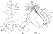
- FIG. 1A a three-dimensional diagram showing a hub sealing apparatus for windmills according to a first embodiment that is cut open to reveal its cross section.
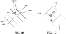
- FIG. 1B is a partial schematic diagram showing a top sealing ring and a middle sealing ring in exploded view of the first embodiment.
- FIG. 1C is a partial schematic diagram showing a blade and the top sealing ring in an exploded view.
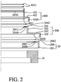
- FIG. 2 is a partial schematic diagram showing the different portions of the hub sealing apparatus in an exploded view of the first embodiment.
- the hub sealing apparatus is adapted to be mounted on a hub 10 while the hub 10 is coupled to a bearing outer ring 101, where the bearing outer ring 10 is further coupled to an internal gear 11 of a bearing inner ring (not shown), and an internal gear 11 of the bearing inner ring is coupled to a blade 12.
- the bearing outer ring 11 may be securely fixed to the hub 10 by a plurality of bolts 103, and similarly the blade 12 may be securely fixed to the internal gear 11 of the bearing inner ring by such bolts 103.
- the hub sealing apparatus is provided to address a conventional leaking problem that generally occurs at the interface (such as an interval) between the hub 10 and the bearing outer ring 101, and also at the interface (or an interval) between the internal gear 11 of the bearing inner ring and the blade 12.
- the hub sealing apparatus comprises a bottom sealing ring 20, a middle sealing ring 30 and a top sealing ring 40.
- the cross section of the bottom sealing ring 20 is formed like the letter "L", whereas the bottom sealing ring 20 is mounted and fixed to the hub 10.
- the bottom sealing ring 20 may be configured with a bottom support 200 and an interface 201 in a manner that the bottom support 200 is mounted to an end of the hub 10, and the interface 201 may be disposed so as to correspond to the periphery of the hub 10 while allowing the bottom support 200 to couple with the interface 201.
- one surface of the bottom support 200 is formed with a bottom ring groove 2000, a recess, e.g.
- the sealant 2002 is an elastic sealing part (e.g. an elastic sealing ring).
- the middle sealing ring 30 may be formed in a double-L shape in cross section, whereas the middle sealing ring 30 is mounted on the bottom support 200 while being arranged neighboring to the bearing outer ring 101.
- the middle sealing ring 30 is composed of multiple ring segments such as two middle half rings 300 that are capable of interconnecting to each other for forming a full ring.
- the two ends of each middle half ring 300 are formed respectively with a middle lug 301 to be used for coupling to the corresponding middle lug 301 formed on the other middle half ring so as to form the complete middle sealing ring 30.
- each of the two middle half rings 300 is configured with half of a middle coupler 302, half of a middle extension part 303 and half of a middle support 304.
- the middle coupler 302 is arranged to couple to an end of the middle extension part 303, whereas the middle coupler 302 has a middle shoulder part 305 formed on one end thereof for abutting against the interface 201 of the bottom sealing ring 20, and thus enabling the middle sealing ring 30 to engage exactly with the bottom sealing ring 20.
- the middle coupler 302 may be further formed with a protrusion, e.g. a middle block 3020 at a position corresponding to the bottom slot 2001 for allowing the same to be inset into the bottom slot 2001, so as to fixedly secure the middle sealing ring 30 to the bottom sealing ring 20 and to simultaneously seal the bottom slot 2001.
- the middle coupler 302 is formed with a plurality of middle coupling holes (not shown) at positions corresponding to the plural bottom fixing holes, so that each middle coupling hole can be fitted to the bottom fixing hole corresponding thereto by a fixing element 3021, so as to lock the middle sealing ring 30 and the bottom sealing ring 20 together.
- the middle support 304 is coupled to an end of the middle extension part 303 other than the end coupling to the middle coupler 302, whereas one surface of the middle support 304 is formed with a middle ring groove 3040, a recess, e.g. a middle slot 3041, and a plurality of middle fixing holes (not shown), in such a manner that the middle ring groove 3040 and the middle slot 3041 are arranged between the middle fixing holes while allowing the middle ring groove 3040 to be filled by a sealant 3042.
- the sealant 3042 is an elastic sealing part.
- the cross section of the top sealing ring 40 is formed like the letter "L,” whereas the top sealing ring 40 is mounted on the middle support 304 while allowing the same to be arranged neighboring to the blade 12.
- the top sealing ring 40 composed of multiple top ring segments such as two top half rings 400 that are capable of interconnecting to each other for forming a full ring, and in the case of half rings the two ends of each top half ring 400 are formed respectively with a top lug 401 to be used for coupling to the corresponding top lug 401 formed on another top half ring 400 so as to form the complete top sealing ring 40.
- each of the two top half rings 400 is configured with half of a top coupler 402 and half of a top neck 403.
- the top coupler 402 is arranged to couple to the top neck 403, whereas the top coupler 402 has a top shoulder part 4020 formed on an end thereof, for abutting against the middle extension part 303, and thus enabling the top sealing ring 40 to engage exactly with the middle sealing ring 30.
- the top coupler 402 may be further formed with a protrusion, e.g. a top block 4021 at a position corresponding to the middle slot 3041 for allowing the same to inset into the middle slot 3041, so as to fixedly secure the top sealing ring 40 to the middle sealing ring 30, and simultaneously seal the middle slot 3041.
- the top coupler 402 is formed with a plurality of top coupling holes at positions corresponding to the plural middle fixing holes, so that each middle coupling hole can be fitted to the bottom fixing hole corresponding thereto by a fixing element 4022 (not shown), so as to lock the top sealing ring 40 and the middle sealing ring 30 together.
- one surface of the top neck 403 that is orientated facing toward the blade 12 is formed with two top ring grooves 4030 while allowing each of the two top ring grooves 4030 to be filled with a sealant 4031 for sealing the gap formed between the blade 12 and the top sealing ring 40.
- the sealant 4031 is an elastic sealing part.
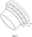
- FIG. 3 is a three-dimensional diagram showing a hub sealing apparatus for windmills according to a second embodiment.
- the bottom sealing ring 20A, the middle sealing ring 30A and the top sealing ring 40A are all formed respectively as a complete ring.
- all of the other components of the bottom sealing ring 20A, the middle sealing ring 30A and the top sealing ring 40A are exactly the same as in the first embodiment, and thus will not be described further herein.
- FIG. 4 is a three-dimensional diagram showing a hub sealing apparatus for windmills according to a third embodiment.
- the middle sealing ring 30 and the top sealing ring 40 may be exactly the same as those disclosed in the first embodiment, but the bottom sealing ring 20B is also composed of multiple bottom ring segments such as two bottom half rings 200B, where the two ends of each bottom half ring 200B are formed respectively with a bottom lug 201B to be used for coupling to the corresponding bottom lug 201B of another middle half ring, so as to form the complete bottom sealing ring 20B.
- the bottom sealing ring 20B may be structurally the same as those disclosed in the foregoing embodiments and thus will not be described further herein.
- FIG. 5 shows a windmill and a partial enlargement of the windmill.
- the windmill includes at least one blade 60, a shaft 61, a hub 62, a nacelle 63, a generating unit 64, a tower 65 and at least one hub sealing apparatus 5.
- the generating unit 64 is installed in the nacelle 63.
- the nacelle 63 is coupled to the tower 65.
- the shaft 61 is installed in the nacelle 63 and coupled to the generating unit 64.
- the hub 62 is coupled to the shaft 61.
- the hub 62 has at least one bearing outer ring and at least one internal gear of a bearing inner ring.
- the bearing outer ring is coupled to the internal gear of the bearing inner ring.
- the internal gear of the bearing inner ring is coupled to the blade 60.
- the bearing outer ring and the internal gear of the bearing inner ring are structurally the same as those disclosed in the foregoing embodiments and thus will not be described further herein.
- the hub sealing apparatus 5 is coupled to the blade 60 and the hub 62.
- the hub sealing apparatus 5 may be structurally the same as those disclosed in the foregoing embodiments and thus will not be described further herein.
- the hub 62 When a wind force acts on the blade 60, the hub 62 is rotated by the blade 60.
- the shaft 61 is driven by the rotating hub 62.
- the generating unit 64 is driven by the shaft 61, so that the generating unit 64 is able to generate electricity.
- the hub sealing apparatus 5 can be replaced easily if needed, and can achieve a superior sealing effect.
- the hub sealing apparatus for windmills disclosed herein is substantially an assembly of multiple sealing rings that can be detached and replaced easily, and is designed with a flexible architecture for allowing the sealing apparatus to be adapted to any type of windmills and thus achieving a good sealing effect.
- the hub sealing apparatus can provide multiple seals to the hub to achieve a better sealing effect and also to prevent leakage or permeation.
Landscapes
- Engineering & Computer Science (AREA)
- General Engineering & Computer Science (AREA)
- Mechanical Engineering (AREA)
- Life Sciences & Earth Sciences (AREA)
- Sustainable Development (AREA)
- Sustainable Energy (AREA)
- Chemical & Material Sciences (AREA)
- Combustion & Propulsion (AREA)
- Wind Motors (AREA)
- Gasket Seals (AREA)
Claims (16)
- Nabendichtungsvorrichtung zur Dichtung eines Zwischenraums zwischen einer Nabe (10) und einem Blatt (12) einer Windkraftanlage, wobei die Nabendichtungsvorrichtung umfasst:einen unteren Dichtungsring (20), der konfiguriert ist, an der Nabe (10) dichtend angeordnet zu sein,einen oberen Dichtungsring (40), der konfiguriert ist, an dem Blatt (12) rotierend dichtend angeordnet zu sein, undeinen mittleren Dichtungsring (30), der konfiguriert ist, an dem oberen Dichtungsring (40) und dem unterem Dichtungsring (20) dichtend angeordnet zu sein, um die oberen und unteren Dichtungsringe (20, 40) miteinander zu verbinden,dadurch gekennzeichnet, dass
der untere Dichtungsring (20) ein unteres Unterstützungselement (200) umfasst und der mittlere Dichtungsring (30) ein mittleres Kopplungselement (302) umfasst, das konfiguriert ist, an dem unteren Unterstützungselement (200) dichtend angeordnet zu sein, wobei entweder das untere Unterstützungselement (200) oder das mittlere Kopplungselement (302) eine darin ausgebildete Aussparung aufweist und das jeweils andere von dem unteren Unterstützungselement (200) und dem mittleren Kopplungselements (302) einen der Aussparung entsprechenden Vor sprung aufweist, um den Zwischenraum zwischen dem unteren Unterstützungselement (200) und dem mittleren Kopplungselement (302) abzudichten, wenn der Vorsprung in der Aussparung angeordnet ist, wobei das mittlere Kopplungselement (302) ein mittleres Schulterteil (305) aufweist, das an einem Ende desselben ausgebildet ist, um eine zwischen dem unteren Unterstützungselement (100) und dem mittleren Kopplungselement (302) gebildete Naht abzudecken. - Nabendichtungsvorrichtung nach Anspruch 1, bei der ein Zwischenraum zwischen dem oberen Dichtungsring (40) und dem Blatt (12) zwischen einander zugewandten Flächen des oberen Dichtungsrings (40) und des Blattes (12) gebildet ist, wobei ferner eine Ringnut (2000) in der Fläche des oberen Dichtungsrings (40) ausgebildet und ein elastisches Dichtungselement zur Platzierung in der Ringnut (2000) angeordnet sind, um dadurch den Zwischenraum zwischen dem oberen Dichtungsring (40) und dem Blatt (12) abzudichten, wobei ein Zwischenraum zwischen dem oberen Dichtungsring (40) und dem Blatt (12) zwischen einander zugewandten Flächen des oberen Dichtungsrings (45) und des Blattes (12) gebildet ist, und wobei ferner eine Vielzahl von Ringnuten (2000) an der Fläche des oberen Dichtungsrings (40) und eine Vielzahl von elastischen Dichtungselementen, die jeweils einer der Vielzahl von Ringnuten (2000) entsprechen und zur Anordnung in der entsprechenden Ringnut (2000) dienen, ausgebildet sind, um dadurch den Zwischenraum zwischen dem oberen Dichtungsring (40) und dem Blatt (12) abzudichten.
- Nabendichtungsvorrichtung nach Anspruch 2, bei der das untere Unterstützungselement (200) eine Nut und ein elastisches Dichtungselement aufweist, das dazu dient, in der Nut platziert zu werden, um so den Zwischenraum zwischen dem unteren Unterstützungselementen (200) und dem mittleren Kopplungselement (302) abzudichten.
- Nabendichtungsvorrichtung nach Anspruch 1, bei der der mittlere Dichtungsring (30) ein mittleres Unterstützungselement (304) aufweist und der obere Dichtungsring (40) ein oberes Kopplungselement (402) aufweist, das konfiguriert ist, an dem mittleren Unterstützungselement (304) dichtend angeordnet zu werden, wobei das mittlere Unterstützungselement (304) eine Nut und ferner ein elastisches Dichtungselement aufweist, das dazu dient, in der Nut platziert zu werden, um so einen Zwischenraum zwischen dem mittleren Unterstützungselement (304) und dem oberen Kopplungselement (402) abzudichten, wobei entweder das mittlere Unterstützungselement (304) oder das obere Kopplungselement (402) eine darin ausgebildete Aussparung aufweist und das jeweils andere von dem mittleren Unterstützungselement (304) und dem oberen Kopplungselement (402) einen der Aussparung entsprechenden Vorsprung aufweist, um so einen Zwischenraum zwischen dem mittleren Unterstützungselement (304) und dem oberen Kopplungselement (402) abzudichten, wenn der Vorsprung in der Aussparung angeordnet ist, wobei das mittlere Unterstützungselement (304) eine Nut und ferner ein elastisches Dichtungselement aufweist, das dazu dient, in der Nut angeordnet zu werden, und dadurch einen Zwischenraum zwischen dem mittleren Unterstützungselement (304) und dem oberen Kopplungselement (402) abzudichten, wobei entweder das mittlere Unterstützungselement (304) oder das obere Kopplungselement (402) eine darin ausgebildete Aussparung aufweist und das jeweils andere von dem mittleren Unterstützungselement (364) und dem oberen Kopplungselement (402) einen der Aussparung entsprechenden Vorsprung aufweist, um so einen Zwischenraum zwischen dem mittleren Unterstützungselement (304) und dem oberen Kopplungselement (402) abzudichten, wenn der Vorsprung in der Nut angeordnet ist, und wobei das obere Kopplungselement (402) ein oberes Schulterelement (4020) aufweist, das an einem Ende desselben ausgebildet ist, um eine zwischen dem mittleren Unterstützungselement (304) und dem oberen Kupplungselement (402) gebildete Naht abzudecken.
- Nabendichtungsvorrichtung nach Anspruch 1, bei der mindestens einer der oberen, unteren und mittleren Dichtungsringe (40, 20,30) eine Vielzahl von Ringsegmenten aufweist, die konfiguriert sind, einen vollständigen Ring zu bilden, wenn diese in der Dichtungsvorrichtung angeordnet sind.
- Nabendichtungsvorrichtung nach Anspruch 5, bei der die Vielzahl von Ringsegmenten zwei halbe Ringe umfasst, wobei jedes der Vielzahl von Ringsegmenten zwei Haltevorrichtungen aufweist, die jeweils an zwei Enden desselben ausgebildet sind, und wobei jeder der oberen, unteren und mittleren Dichtungsringe (40, 20,30) eine Vielzahl von Ringsegmenten aufweist, die konfiguriert sind, einen vollständigen Ring zu bilden, wenn diese in der Dichtungsvorrichtung angeordnet sind.
- Windkraftanlage mit einer Nabendichtungsvorrichtung nach einem der Ansprüche 1 bis 6 umfassend:eine Nabe (10)mindestens ein Blatt (12) undeine Nabendichtungsvorrichtung zum Abdichten eines Zwischenraums zwischen der Nabe (10) und dem Blatt (12), umfassend:einen unteren Dichtungsring (20), der lösbar dichtend an der Nabe (10) angeordnet ist,einen oberen Dichtungsring (40), der lösbar rotierbar dichtend an dem Blatt (12) angeordnet ist, undeinen mittleren Dichtungsring (30), der lösbar dichtend an dem oberen Dichtungsring (40) und dem unteren Dichtungsring (20) angeordnet ist, um die oberen und unteren Dichtungsringe (20) zu verbinden.
- Windkraftanlage nach Anspruch 7, bei der ein Zwischenraum zwischen dem oberen Dichtungsring (40) und dem Blatt (12) zwischen einander zugewandten Flächen des oberen Dichtungsrings (40) und des Blatts (12) gebildet ist und ferner eine Ringnut (2000) in der Fläche des oberen Dichtungsrings (40) ausgebildet und ein elastisches Dichtungselement lösbar in der Ringnut (2000) angeordnet ist, um dadurch den Zwischenraum zwischen dem oberen Dichtungsring (40) und dem Blatt (12) abzudichten, wobei ein Zwischenraum zwischen dem oberen Dichtungsring (40) und dem Blatt (12) zwischen einander zugewandten Flächen des oberen Dichtungsrings (40) und des Blatts (12) gebildet ist und ferner eine Vielzahl von Ringnuten (2000) an der Fläche des oberen Dichtungsrings (40) ausgebildet und eine Vielzahl von elastischen Dichtungselementen, die jeweils einer der Vielzahl von Ringnuten (2000) entsprechen, lösbar in den entsprechenden Ringnuten (2000) angeordnet sind, um dadurch den Zwischenraum zwischen dem oberen Dichtungsring (43) und dem Blatt (12) abzudichten.
- Windkraftanlage nach Anspruch 7, bei der der untere Dichtungsring (20) ein unteres Unterstützungselement (200) aufweist und der mittlere Dichtungsring (30) ein mittleres Kupplungselement (302) aufweist, das lösbar dichtend an dem unteren Unterstützungselement (200) angeordnet ist, wobei das untere Unterstützungselement (200) eine Nut aufweist, in der ferner ein elastisches Dichtungselement lösbar angeordnet ist, um dadurch einen Zwischenraum zwischen dem unteren Unterstützungselement (200) und dem mittleren Kopplungselement (302) abzudichten, wobei entweder das untere Unterstützungselement (200) oder das mittlere. Kopplungselement (302) eine Aussparung aufweist und das jeweils andere von dem unteren Unterstützungselement (200) und dem mittleren Kopplungselement (302) einen Vorsprung aufweist, wobei der Vorsprung lösbar in der Aussparung angeordnet ist, um einen Zwischenraum zwischen dem unteren Unterstützungselement (200) und dem mittleren Kopplungselement (302) abzudichten, wobei das untere Unterstützungselement (200) eine Nut aufweist, in der ferner ein elastisches Dichtungselement lösbar angeordnet ist, um so einen Zwischenraum zwischen dem unteren Unterstützungselement (200) und dem mittleren Kopplungselement (302) abzudichten, wobei entweder das untere Unterstützungselement (200) oder das mittlere Kopplungselement (302) eine Aussparung aufweist und das jeweils andere von dem unteren Unterstützungselement (200) und dem mittleren Kopplungselement (302) einen Vorsprung aufweist, wobei der Vorsprung lösbar in der Aussparung angeordnet ist, um einen Zwischenraum zwischen dem unteren Unterstützungselement (100) und dem mittleren Kopplungselement (302) abzudichten, und wobei das mittlere Kopplungselement (302) ein mittleres Schulterelement (305) aufweist, das an einem Ende desselben ausgebildet ist, um eine zwischen dem unteren Unterstützungselement (200) und dem mittleren Kopplungselement (302) gebildete Naht abzudecken.
- Windkraftanlage nach Anspruch 7, bei der der mittlere Dichtungsring (30) ein mittleres Unterstützungselement (304) und der obere Dichtungsring (40) ein oberes Kopplungselement (402) aufweisen, das lösbar dichtend an dem mittleren Unterstützungselement (304) angeordnet ist, wobei das mittlere Unterstützungselement (304) eine Nut aufweist, in der ferner ein elastisches Dichtungselement lösbar angeordnet ist, um so einen Zwischenraum zwischen dem mittleren Unterstützungselement (304) und dem oberen Kopplungselement (402) abzudichten, wobei entweder das mittlere Unterstützungselement (304) oder das obere Kopplungselement (402) eine Aussparung aufweist und das jeweils andere von dem mittleren Unterstützungselement (304) und dem oberen Kopplungselement (402) einen Vorsprung aufweist, wobei der Vorsprung lösbar in der Aussparung angeordnet ist, um einen Zwischenraum zwischen dem mittleren Unterstützungselement (304) und dem oberen Kopplungselement (402) abzudichten, wobei das mittlere Unterstützungselement (304) eine Nut aufweist, in der ferner ein elastisches Dichtungselement lösbar angeordnet ist, um so einen Zwischenraum zwischen dem mittleren Unterstützungselement (304) und dem oberen Kopplungselement (402) abzudichten, wobei entweder das mittlere Unterstützungselement (304) oder das untere Kopplungselement (402) eine darin ausgebildete Aussparung aufweist und das jeweils andere von dem mittleren Unterstützungselement (304) und dem oberen Kopplungselement (402) einen Vorsprung aufweist, wobei der Vorsprung lösbar in der Aussparung angeordnet ist, um einen Zwischenraum zwischen dem mittleren Unterstützungselement (304) und dem oberen Kupplungselement (402) abzudichten, und wobei das obere Kopplungselement (402) ein oberes Schulterelement (4020) aufweist, das an einem Ende desselben ausgebildet ist, um eine zwischen dem mittleren Unterstützungselement (304) und dem oberen Kopplungselement (402) gebildete Naht abzudecken.
- Windkraftanlage nach Anspruch 10, bei der mindestens einer der oberen, unteren und mittleren Dichtungsringe (40, 20,30) eine Vielzahl von Ringsegmenten umfasst, wobei die Vielzahl von Ringsegmenten zwei Halbringe umfasst, wobei jedes der Vielzahl von Ringsegmenten zwei Haltevorrichtungen aufweist, die jeweils an zwei Enden desselben ausgebildet sind, und wobei jeder der oberen, unteren und mittleren Dichtungsringe (40, 20,30) aufweist.
- Herstellungsverfahren einer Windkraftanlage umfassend:das Bereitstellen einer Nabe (10) und mindestens eines Blattes (12),das dichtende Anordnen eines unteren Dichtungsrings (20) an der Nabe (10),das rotierbar dichtende Anordnen eines oberen Dichtungsrings (40) an dem Blatt (12),gekennzeichnet, durch
das dichtende Anordnen eines mittleren Dichtungsrings (30) an dem oberen Dichtungsring (40) und dem unteren Dichtungsring (20), um so die oberen und unteren Dichtungsringe (20) miteinander zu verbinden,
das Ausbilden eines unteren Unterstützungselements (200) an dem unteren Dichtungsring (20),
das Ausbilden eines mittleren Kopplungselements (302) an dem mittleren Dichtungsring (30) und
das dichtende Anordnen des mittleren Kopplungselements (302) an dem unteren Unterstützungselement (200),
das Ausbilden einer Nut in dem unteren Unterstützungselement (200) und das Anordnen eines elastischen Dichtungselements in der Nut, um so einen Zwischenraum zwischen dem unteren Unterstützungselement (200) und dem mittleren Kopplungselement (302) abzudichten,
das jeweilige Ausbilden einer Aussparung und eines Vorsprung an entweder dem unteren Unterstützungselement (200) oder dem mittleren Kopplungselement (302) und das Anordnen des Vorsprungs in der Aussparung, um einen Zwischenraum zwischen dem unteren Unterstützungselement (200) und dem mittleren Kopplungselement (302) abzudichten,
das Ausbilden einer Nut in dem unteren Unterstützungselement (200) und das Anordnen eines elastischen Dichtungselements in der Nut, um einen Zwischenraum zwischen dem unteren Unterstützungselement (200) und dem mittleren Kopplungselement (302) abzudichten, und
das jeweilige Ausbilden einer Aussparung und eines Vorsprungs an entweder dem unteren Unterstützungselement (200) oder dem mittleren Kopplungselement (302) und das Anordnen des Vorsprungs in der Aussparung, um einen Zwischenraum zwischen dem unteren Unterstützungselement (100) und dem mittleren Krupplungselement (302) abzudichten. - Verfahren nach Anspruch 12, ferner umfassend:das Ausbilden eines Zwischenraums zwischen dem oberen Dichtungsring (40) und dem Blatt (12) zwischen einander zugewandten Flächen des oberen Dichtungrings und des Blatts (12),das Ausbilden einer Ringnut (2000) an der Fläche des oberen Dichtungsrings (40) und das Anordnen eines elastischen Dichtungselements in der Ringnut (2000), um dadurch den Zwischenraum zwischen dem oberen Dichtungsring (40) und dem Blatt (12) abzudichten,das Bilden eines Zwischenraums zwischen dem oberen Dichtungsring (40) und dem Blatt (12) zwischen einander zugewandten Flächen des oberen Dichtungsrings (40) und des Blatts (12),das Ausbilden einer Vielzahl von Ringnuten (2000) an der Oberfläche des oberen Dichtungsrings (40) unddas Anordnen einer Vielzahl von jeweils einer der Vielzahl von Ringnuten (2000) entsprechenden elastischen Dichtungselementen in der entsprechenden Ringnut (2000), um somit den Zwischenraum zwischen dem oberen Dichtungsring (40) und dem Blatt (12) abzudichten.
- Verfahren nach Anspruch 12, ferner umfassend:das Ausbilden eines mittleren Schulterelements (305) an einem Ende des mittleren Kopplungselements (302), um eine zwischen dem unteren Unterstützungselement (200) und dem mittleren Kopplungselement (302) gebildete Naht abzudecken.
- Verfahren nach Anspruch 12, ferner umfassend.das Ausbilden eines mittleren Unterstützungselements (304) an dem mittleren Dichtungsring (30),das Ausbilden eines oberen Kopplungselements (402) an dem oberen Dichtungsring (40) unddas abdichtende Anordnen des oberen Kopplungselements (402) an dem mittleren Unterstützungselement (304),das Ausbilden einer Nut in dem mittleren Unterstützungselement (304) und das Anordnen eines elastischen Dichtungselements in der Nut, um dadurch einen Zwischenraum zwischen dem mittleren Unterstützungselement (304) und dem oberen Kopplungselement (402) abzudichten,
das jeweilige Ausbilden einer Aussparung und eines Vorsprung an entweder dem mittleren Unterstützungselement (304) oder dem oberen Kopplungselement (402) und das Anordnen des Vorsprungs in der Aussparung, um einen Zwischenraum zwischen dem mittleren Unterstützungselement (304) und dem oberen Kopplungselement (402) abzudichten,
das Ausbilden einer Nut in dem mittleren Unterstützungselement (304) und das Anordnen eines elastischen Dichtungselements in der Nut, um damit einen Zwischenraum zwischen dem mittleren Unterstützungselement (304) und dem oberen Kopplungselement (402) abzudichten, und
das jeweilige Ausbilden einer Aussparung und eines Vorsprungs an entweder dem mittleren Unterstützungselement (304) oder dem oberen Kopplungselement (402) und das Anordnen des Vorsprungs in der Aussparung, um einen Zwischenraum zwischen dem mittleren Unterstützungselement (364) und dem oberen Kopplungselement (402) abzudichten,
das Ausbilden eines oberen Schulterelements (4020) an einem Ende des oberen Kopplungselements (402), um eine zwischen dem mittleren Unterstützungselement (304) und dem oberen Kopplungselement (402) gebildete Naht abzudecken. - Verfahren nach Anspruch 15, bei dem mindestens einer der oberen, unteren und mittleren Dichtungsringe (40, 20, 30) eine Vielzahl von Ringsegmenten umfasst, ferner umfassend das Anordnen der Vielzahl von Ringsegmenten, um einen vollständigen Ring zu bildern, wobei die Vielzahl von geringen Segmenten zwei halbe Ringe umfasst, wobei jedes der Vielzahl von Ringsegmenten zwei Befestigungsmittel umfasst, die jeweils an zwei Enden desselben ausgebildet sind, und wobei die oberen, unteren und mittleren Dichtungsringe (40, 20,30) eine Vielzahl von Ringsegmenten umfasst.
Applications Claiming Priority (1)
| Application Number | Priority Date | Filing Date | Title |
|---|---|---|---|
| TW100143430A TWI441981B (zh) | 2011-11-25 | 2011-11-25 | 風力機輪轂密封裝置 |
Publications (3)
| Publication Number | Publication Date |
|---|---|
| EP2597301A2 EP2597301A2 (de) | 2013-05-29 |
| EP2597301A3 EP2597301A3 (de) | 2014-03-26 |
| EP2597301B1 true EP2597301B1 (de) | 2017-03-01 |
Family
ID=46880619
Family Applications (1)
| Application Number | Title | Priority Date | Filing Date |
|---|---|---|---|
| EP12183965.8A Not-in-force EP2597301B1 (de) | 2011-11-25 | 2012-09-12 | Windmühle und Nabenversiegelungsvorrichtung dafür |
Country Status (4)
| Country | Link |
|---|---|
| US (1) | US9109579B2 (de) |
| EP (1) | EP2597301B1 (de) |
| DK (1) | DK2597301T3 (de) |
| TW (1) | TWI441981B (de) |
Families Citing this family (8)
| Publication number | Priority date | Publication date | Assignee | Title |
|---|---|---|---|---|
| EP2966296A1 (de) * | 2014-07-10 | 2016-01-13 | ALSTOM Renewable Technologies | Blattwinkelverstellung |
| CN106352082B (zh) * | 2016-08-29 | 2018-02-16 | 优利康达(天津)科技有限公司 | 一种风机密封结构 |
| WO2018141442A1 (en) * | 2017-01-31 | 2018-08-09 | Siemens Wind Power A/S | Rotor bearing with a magnetically coupled bearing cover |
| CN109435258B (zh) * | 2018-10-22 | 2020-11-24 | 江苏双瑞风电叶片有限公司 | 一种风电叶片根部连接系统的密封方法 |
| EP3825545B1 (de) * | 2019-11-21 | 2022-06-01 | Wobben Properties GmbH | Rotorblatt, rotor und windenergieanlage sowie verfahren |
| US12270373B2 (en) | 2019-12-20 | 2025-04-08 | Vestas Wind Systems A/S | Relating to wind turbine blade root cover |
| EP4455500A4 (de) * | 2021-12-24 | 2025-12-10 | Nabtesco Corp | Schmiermittelleckageunterdrückungsmechanismus und getriebemechanismus |
| EP4265907A1 (de) * | 2022-04-19 | 2023-10-25 | LM Wind Power A/S | Schmiermittelrückhaltesysteme |
Citations (1)
| Publication number | Priority date | Publication date | Assignee | Title |
|---|---|---|---|---|
| JPH0882322A (ja) * | 1994-09-13 | 1996-03-26 | Mitsubishi Heavy Ind Ltd | 風車発電機用動翼軸受シール装置 |
Family Cites Families (26)
| Publication number | Priority date | Publication date | Assignee | Title |
|---|---|---|---|---|
| US1169583A (en) * | 1914-11-24 | 1916-01-25 | Adrian O Van Dervort | Metallic packing. |
| FR2742837B1 (fr) * | 1995-12-21 | 1998-02-20 | Eurocopter France | Dispositif d'etancheite pour arbre tournant |
| US5605337A (en) * | 1996-03-13 | 1997-02-25 | General Motors Corporation | Pivoting seal for oil-filled rotating machine |
| GB2317652B (en) | 1996-09-26 | 2000-05-17 | Rolls Royce Plc | Seal arrangement |
| DE102005026141C5 (de) * | 2005-06-06 | 2025-03-27 | Imo Momentenlager Gmbh | Windkraftanlage mit einer Lagereinheit für ein langgestrecktes Rotorblatt |
| US7331761B2 (en) | 2005-11-10 | 2008-02-19 | Kaydon Corporation | Wind turbine pitch bearing and method |
| DE102007024528A1 (de) | 2007-05-24 | 2008-11-27 | Voith Patent Gmbh | Energieerzeugungsanlage, angetrieben durch eine Wind- oder Wasserströmung |
| JP5022103B2 (ja) | 2007-05-25 | 2012-09-12 | 三菱重工業株式会社 | 風力発電装置 |
| JP2009052681A (ja) | 2007-08-28 | 2009-03-12 | Ntn Corp | 軸受構造 |
| TWM339584U (en) | 2007-12-07 | 2008-09-01 | United Ship Design & Dev Ct | An embedded stud with taper surface and key for root joint of wind turbine blade |
| EP2080904B8 (de) | 2008-01-17 | 2011-06-22 | Gamesa Innovation & Technology, S.L. | Getriebeeinheit für eine Windturbine |
| EP2096303A1 (de) | 2008-02-29 | 2009-09-02 | Darwind Holding B.V. | Windturbine mit Tragedichtung |
| CN101715520A (zh) | 2008-07-17 | 2010-05-26 | 三菱重工业株式会社 | 轴承结构及风力发电装置 |
| EP2330297A4 (de) | 2008-10-03 | 2012-03-28 | Nabtesco Corp | Spitzentreibervorrichtung für ein windrad |
| TW201014970A (en) | 2008-10-14 | 2010-04-16 | Inst Nuclear Energy Res | Mechanism to control the inclination angle of blades |
| DE102009035248B4 (de) | 2009-07-29 | 2011-12-08 | Suzlon Energy Gmbh | Gehäuse für eine Windturbine |
| US8766883B2 (en) | 2009-08-20 | 2014-07-01 | Emagin Corporation | Dual-mode AMOLED pixel driver, a system using a dual-mode AMOLED pixel driver, and a method of operating a dual-mode AMOLED pixel driver |
| JP2011064224A (ja) | 2009-09-15 | 2011-03-31 | Ntn Corp | 風力発電用主軸支持装置、該装置に用いられる複列自動調心ころ軸受 |
| TWM374507U (en) | 2009-09-16 | 2010-02-21 | United Ship Design & Dev Ct | A device to reduce blade pressure of wind turbine |
| CN201588744U (zh) | 2009-11-03 | 2010-09-22 | 南车戚墅堰机车车辆工艺研究所有限公司 | 风力发电增速齿轮箱密封装置 |
| TW201126063A (en) | 2010-01-20 | 2011-08-01 | zhang-hui Tong | Wind power generator having waterproof structure |
| TWM381684U (en) | 2010-01-20 | 2010-06-01 | zhang-hui Tong | Wind powered electricity generation device with water-proofing structure |
| EP2375092B1 (de) | 2010-04-06 | 2013-03-27 | Siemens Aktiengesellschaft | Schmiersystem für Lager |
| US20110138963A1 (en) | 2010-06-29 | 2011-06-16 | Pischel Klaus | Active sealing-draining device |
| CN201714586U (zh) | 2010-07-20 | 2011-01-19 | 中船重工(重庆)海装风电设备有限公司 | 海上风力发电系统 |
| US9850881B2 (en) * | 2011-02-21 | 2017-12-26 | Vestas Wind Systems A/S | Sealing system and method of maintaining a clean environment in a wind turbine by absorbing lubricant used in the pitch or yaw bearings |
-
2011
- 2011-11-25 TW TW100143430A patent/TWI441981B/zh not_active IP Right Cessation
-
2012
- 2012-07-31 US US13/563,479 patent/US9109579B2/en active Active
- 2012-09-12 DK DK12183965.8T patent/DK2597301T3/en active
- 2012-09-12 EP EP12183965.8A patent/EP2597301B1/de not_active Not-in-force
Patent Citations (1)
| Publication number | Priority date | Publication date | Assignee | Title |
|---|---|---|---|---|
| JPH0882322A (ja) * | 1994-09-13 | 1996-03-26 | Mitsubishi Heavy Ind Ltd | 風車発電機用動翼軸受シール装置 |
Also Published As
| Publication number | Publication date |
|---|---|
| EP2597301A3 (de) | 2014-03-26 |
| US9109579B2 (en) | 2015-08-18 |
| EP2597301A2 (de) | 2013-05-29 |
| US20130136604A1 (en) | 2013-05-30 |
| DK2597301T3 (en) | 2017-06-19 |
| TWI441981B (zh) | 2014-06-21 |
| TW201321602A (zh) | 2013-06-01 |
Similar Documents
| Publication | Publication Date | Title |
|---|---|---|
| EP2597301B1 (de) | Windmühle und Nabenversiegelungsvorrichtung dafür | |
| EP2565475A2 (de) | Getriebe für eine Windturbine | |
| CN102147005A (zh) | 风力发电机齿轮箱的输入端 | |
| JP5615349B2 (ja) | 再生エネルギー型発電装置及び油圧ポンプの取付け方法 | |
| CN202451792U (zh) | 风电主齿轮箱中高速级组合密封回油机构 | |
| JP4969708B1 (ja) | 再生エネルギー型発電装置及び油圧ポンプの取付け方法 | |
| GB2437534A (en) | Marine turbine | |
| US11946455B2 (en) | Wind energy generation system | |
| CN104595107A (zh) | 一种风力发电机组叶片变桨机构 | |
| KR101390280B1 (ko) | 풍력발전기 | |
| CN211423333U (zh) | 一种齿轮箱挡油结构及风电齿轮箱 | |
| CN202040015U (zh) | 风力发电机齿轮箱的输入端 | |
| CN212455427U (zh) | 一种风电齿轮箱箱体 | |
| CN204597693U (zh) | 电机轴承防漏油装置 | |
| CN204553077U (zh) | 一种含有装配补偿器的潮流能发电机组 | |
| CN115163799A (zh) | 一种新型的半直驱风电齿轮箱密封结构 | |
| CN211474346U (zh) | 一种风力发电机组油滑环 | |
| CN207664764U (zh) | 汽轮发电机盘车电机油封端盖 | |
| CN202597183U (zh) | 一种核电站用余热排出泵的轴承保护器 | |
| CN111664242A (zh) | 一种风电齿轮箱箱体 | |
| CN212717886U (zh) | 一种风电齿轮箱箱体 | |
| CN108953569B (zh) | 风机齿轮箱拆卸方法及装置 | |
| CN211820663U (zh) | 风电齿轮箱的空心轴密封结构、风电齿轮箱及风力发电机 | |
| CN221075168U (zh) | 齿轮箱机械密封结构和齿轮箱 | |
| CN217177345U (zh) | 一种垂直轴微耕机变速箱 |
Legal Events
| Date | Code | Title | Description |
|---|---|---|---|
| PUAI | Public reference made under article 153(3) epc to a published international application that has entered the european phase |
Free format text: ORIGINAL CODE: 0009012 |
|
| AK | Designated contracting states |
Kind code of ref document: A2 Designated state(s): AL AT BE BG CH CY CZ DE DK EE ES FI FR GB GR HR HU IE IS IT LI LT LU LV MC MK MT NL NO PL PT RO RS SE SI SK SM TR |
|
| AX | Request for extension of the european patent |
Extension state: BA ME |
|
| PUAL | Search report despatched |
Free format text: ORIGINAL CODE: 0009013 |
|
| AK | Designated contracting states |
Kind code of ref document: A3 Designated state(s): AL AT BE BG CH CY CZ DE DK EE ES FI FR GB GR HR HU IE IS IT LI LT LU LV MC MK MT NL NO PL PT RO RS SE SI SK SM TR |
|
| AX | Request for extension of the european patent |
Extension state: BA ME |
|
| RIC1 | Information provided on ipc code assigned before grant |
Ipc: F03D 11/00 20060101ALI20140214BHEP Ipc: F03D 1/06 20060101AFI20140214BHEP |
|
| 17P | Request for examination filed |
Effective date: 20140926 |
|
| RBV | Designated contracting states (corrected) |
Designated state(s): AL AT BE BG CH CY CZ DE DK EE ES FI FR GB GR HR HU IE IS IT LI LT LU LV MC MK MT NL NO PL PT RO RS SE SI SK SM TR |
|
| 17Q | First examination report despatched |
Effective date: 20160210 |
|
| REG | Reference to a national code |
Ref country code: DE Ref legal event code: R079 Ref document number: 602012029145 Country of ref document: DE Free format text: PREVIOUS MAIN CLASS: F03D0001060000 Ipc: F03D0080000000 |
|
| RIC1 | Information provided on ipc code assigned before grant |
Ipc: F03D 80/00 20160101AFI20160728BHEP |
|
| GRAP | Despatch of communication of intention to grant a patent |
Free format text: ORIGINAL CODE: EPIDOSNIGR1 |
|
| INTG | Intention to grant announced |
Effective date: 20160908 |
|
| GRAS | Grant fee paid |
Free format text: ORIGINAL CODE: EPIDOSNIGR3 |
|
| GRAA | (expected) grant |
Free format text: ORIGINAL CODE: 0009210 |
|
| AK | Designated contracting states |
Kind code of ref document: B1 Designated state(s): AL AT BE BG CH CY CZ DE DK EE ES FI FR GB GR HR HU IE IS IT LI LT LU LV MC MK MT NL NO PL PT RO RS SE SI SK SM TR |
|
| REG | Reference to a national code |
Ref country code: GB Ref legal event code: FG4D |
|
| REG | Reference to a national code |
Ref country code: CH Ref legal event code: EP Ref country code: AT Ref legal event code: REF Ref document number: 871696 Country of ref document: AT Kind code of ref document: T Effective date: 20170315 |
|
| REG | Reference to a national code |
Ref country code: IE Ref legal event code: FG4D |
|
| REG | Reference to a national code |
Ref country code: DE Ref legal event code: R096 Ref document number: 602012029145 Country of ref document: DE |
|
| REG | Reference to a national code |
Ref country code: DK Ref legal event code: T3 Effective date: 20170615 |
|
| REG | Reference to a national code |
Ref country code: NL Ref legal event code: MP Effective date: 20170301 |
|
| REG | Reference to a national code |
Ref country code: LT Ref legal event code: MG4D |
|
| REG | Reference to a national code |
Ref country code: AT Ref legal event code: MK05 Ref document number: 871696 Country of ref document: AT Kind code of ref document: T Effective date: 20170301 |
|
| PG25 | Lapsed in a contracting state [announced via postgrant information from national office to epo] |
Ref country code: NO Free format text: LAPSE BECAUSE OF FAILURE TO SUBMIT A TRANSLATION OF THE DESCRIPTION OR TO PAY THE FEE WITHIN THE PRESCRIBED TIME-LIMIT Effective date: 20170601 Ref country code: HR Free format text: LAPSE BECAUSE OF FAILURE TO SUBMIT A TRANSLATION OF THE DESCRIPTION OR TO PAY THE FEE WITHIN THE PRESCRIBED TIME-LIMIT Effective date: 20170301 Ref country code: GR Free format text: LAPSE BECAUSE OF FAILURE TO SUBMIT A TRANSLATION OF THE DESCRIPTION OR TO PAY THE FEE WITHIN THE PRESCRIBED TIME-LIMIT Effective date: 20170602 Ref country code: LT Free format text: LAPSE BECAUSE OF FAILURE TO SUBMIT A TRANSLATION OF THE DESCRIPTION OR TO PAY THE FEE WITHIN THE PRESCRIBED TIME-LIMIT Effective date: 20170301 Ref country code: FI Free format text: LAPSE BECAUSE OF FAILURE TO SUBMIT A TRANSLATION OF THE DESCRIPTION OR TO PAY THE FEE WITHIN THE PRESCRIBED TIME-LIMIT Effective date: 20170301 |
|
| PG25 | Lapsed in a contracting state [announced via postgrant information from national office to epo] |
Ref country code: ES Free format text: LAPSE BECAUSE OF FAILURE TO SUBMIT A TRANSLATION OF THE DESCRIPTION OR TO PAY THE FEE WITHIN THE PRESCRIBED TIME-LIMIT Effective date: 20170301 Ref country code: SE Free format text: LAPSE BECAUSE OF FAILURE TO SUBMIT A TRANSLATION OF THE DESCRIPTION OR TO PAY THE FEE WITHIN THE PRESCRIBED TIME-LIMIT Effective date: 20170301 Ref country code: BG Free format text: LAPSE BECAUSE OF FAILURE TO SUBMIT A TRANSLATION OF THE DESCRIPTION OR TO PAY THE FEE WITHIN THE PRESCRIBED TIME-LIMIT Effective date: 20170601 Ref country code: RS Free format text: LAPSE BECAUSE OF FAILURE TO SUBMIT A TRANSLATION OF THE DESCRIPTION OR TO PAY THE FEE WITHIN THE PRESCRIBED TIME-LIMIT Effective date: 20170301 Ref country code: AT Free format text: LAPSE BECAUSE OF FAILURE TO SUBMIT A TRANSLATION OF THE DESCRIPTION OR TO PAY THE FEE WITHIN THE PRESCRIBED TIME-LIMIT Effective date: 20170301 Ref country code: LV Free format text: LAPSE BECAUSE OF FAILURE TO SUBMIT A TRANSLATION OF THE DESCRIPTION OR TO PAY THE FEE WITHIN THE PRESCRIBED TIME-LIMIT Effective date: 20170301 |
|
| REG | Reference to a national code |
Ref country code: FR Ref legal event code: PLFP Year of fee payment: 6 |
|
| PG25 | Lapsed in a contracting state [announced via postgrant information from national office to epo] |
Ref country code: NL Free format text: LAPSE BECAUSE OF FAILURE TO SUBMIT A TRANSLATION OF THE DESCRIPTION OR TO PAY THE FEE WITHIN THE PRESCRIBED TIME-LIMIT Effective date: 20170301 |
|
| PG25 | Lapsed in a contracting state [announced via postgrant information from national office to epo] |
Ref country code: CZ Free format text: LAPSE BECAUSE OF FAILURE TO SUBMIT A TRANSLATION OF THE DESCRIPTION OR TO PAY THE FEE WITHIN THE PRESCRIBED TIME-LIMIT Effective date: 20170301 Ref country code: IT Free format text: LAPSE BECAUSE OF FAILURE TO SUBMIT A TRANSLATION OF THE DESCRIPTION OR TO PAY THE FEE WITHIN THE PRESCRIBED TIME-LIMIT Effective date: 20170301 Ref country code: EE Free format text: LAPSE BECAUSE OF FAILURE TO SUBMIT A TRANSLATION OF THE DESCRIPTION OR TO PAY THE FEE WITHIN THE PRESCRIBED TIME-LIMIT Effective date: 20170301 Ref country code: RO Free format text: LAPSE BECAUSE OF FAILURE TO SUBMIT A TRANSLATION OF THE DESCRIPTION OR TO PAY THE FEE WITHIN THE PRESCRIBED TIME-LIMIT Effective date: 20170301 Ref country code: SK Free format text: LAPSE BECAUSE OF FAILURE TO SUBMIT A TRANSLATION OF THE DESCRIPTION OR TO PAY THE FEE WITHIN THE PRESCRIBED TIME-LIMIT Effective date: 20170301 |
|
| PG25 | Lapsed in a contracting state [announced via postgrant information from national office to epo] |
Ref country code: IS Free format text: LAPSE BECAUSE OF FAILURE TO SUBMIT A TRANSLATION OF THE DESCRIPTION OR TO PAY THE FEE WITHIN THE PRESCRIBED TIME-LIMIT Effective date: 20170701 Ref country code: PL Free format text: LAPSE BECAUSE OF FAILURE TO SUBMIT A TRANSLATION OF THE DESCRIPTION OR TO PAY THE FEE WITHIN THE PRESCRIBED TIME-LIMIT Effective date: 20170301 Ref country code: PT Free format text: LAPSE BECAUSE OF FAILURE TO SUBMIT A TRANSLATION OF THE DESCRIPTION OR TO PAY THE FEE WITHIN THE PRESCRIBED TIME-LIMIT Effective date: 20170703 Ref country code: SM Free format text: LAPSE BECAUSE OF FAILURE TO SUBMIT A TRANSLATION OF THE DESCRIPTION OR TO PAY THE FEE WITHIN THE PRESCRIBED TIME-LIMIT Effective date: 20170301 |
|
| REG | Reference to a national code |
Ref country code: DE Ref legal event code: R097 Ref document number: 602012029145 Country of ref document: DE |
|
| PLBE | No opposition filed within time limit |
Free format text: ORIGINAL CODE: 0009261 |
|
| STAA | Information on the status of an ep patent application or granted ep patent |
Free format text: STATUS: NO OPPOSITION FILED WITHIN TIME LIMIT |
|
| 26N | No opposition filed |
Effective date: 20171204 |
|
| PG25 | Lapsed in a contracting state [announced via postgrant information from national office to epo] |
Ref country code: SI Free format text: LAPSE BECAUSE OF FAILURE TO SUBMIT A TRANSLATION OF THE DESCRIPTION OR TO PAY THE FEE WITHIN THE PRESCRIBED TIME-LIMIT Effective date: 20170301 |
|
| REG | Reference to a national code |
Ref country code: CH Ref legal event code: PL |
|
| GBPC | Gb: european patent ceased through non-payment of renewal fee |
Effective date: 20170912 |
|
| PG25 | Lapsed in a contracting state [announced via postgrant information from national office to epo] |
Ref country code: MC Free format text: LAPSE BECAUSE OF FAILURE TO SUBMIT A TRANSLATION OF THE DESCRIPTION OR TO PAY THE FEE WITHIN THE PRESCRIBED TIME-LIMIT Effective date: 20170301 |
|
| REG | Reference to a national code |
Ref country code: IE Ref legal event code: MM4A |
|
| REG | Reference to a national code |
Ref country code: BE Ref legal event code: MM Effective date: 20170930 |
|
| PG25 | Lapsed in a contracting state [announced via postgrant information from national office to epo] |
Ref country code: LU Free format text: LAPSE BECAUSE OF NON-PAYMENT OF DUE FEES Effective date: 20170912 |
|
| PG25 | Lapsed in a contracting state [announced via postgrant information from national office to epo] |
Ref country code: CH Free format text: LAPSE BECAUSE OF NON-PAYMENT OF DUE FEES Effective date: 20170930 Ref country code: LI Free format text: LAPSE BECAUSE OF NON-PAYMENT OF DUE FEES Effective date: 20170930 Ref country code: IE Free format text: LAPSE BECAUSE OF NON-PAYMENT OF DUE FEES Effective date: 20170912 Ref country code: GB Free format text: LAPSE BECAUSE OF NON-PAYMENT OF DUE FEES Effective date: 20170912 |
|
| PG25 | Lapsed in a contracting state [announced via postgrant information from national office to epo] |
Ref country code: BE Free format text: LAPSE BECAUSE OF NON-PAYMENT OF DUE FEES Effective date: 20170930 |
|
| REG | Reference to a national code |
Ref country code: FR Ref legal event code: PLFP Year of fee payment: 7 |
|
| PG25 | Lapsed in a contracting state [announced via postgrant information from national office to epo] |
Ref country code: MT Free format text: LAPSE BECAUSE OF NON-PAYMENT OF DUE FEES Effective date: 20170912 |
|
| PG25 | Lapsed in a contracting state [announced via postgrant information from national office to epo] |
Ref country code: HU Free format text: LAPSE BECAUSE OF FAILURE TO SUBMIT A TRANSLATION OF THE DESCRIPTION OR TO PAY THE FEE WITHIN THE PRESCRIBED TIME-LIMIT; INVALID AB INITIO Effective date: 20120912 |
|
| PG25 | Lapsed in a contracting state [announced via postgrant information from national office to epo] |
Ref country code: CY Free format text: LAPSE BECAUSE OF NON-PAYMENT OF DUE FEES Effective date: 20170301 |
|
| PG25 | Lapsed in a contracting state [announced via postgrant information from national office to epo] |
Ref country code: MK Free format text: LAPSE BECAUSE OF FAILURE TO SUBMIT A TRANSLATION OF THE DESCRIPTION OR TO PAY THE FEE WITHIN THE PRESCRIBED TIME-LIMIT Effective date: 20170301 |
|
| PG25 | Lapsed in a contracting state [announced via postgrant information from national office to epo] |
Ref country code: TR Free format text: LAPSE BECAUSE OF FAILURE TO SUBMIT A TRANSLATION OF THE DESCRIPTION OR TO PAY THE FEE WITHIN THE PRESCRIBED TIME-LIMIT Effective date: 20170301 |
|
| PG25 | Lapsed in a contracting state [announced via postgrant information from national office to epo] |
Ref country code: AL Free format text: LAPSE BECAUSE OF FAILURE TO SUBMIT A TRANSLATION OF THE DESCRIPTION OR TO PAY THE FEE WITHIN THE PRESCRIBED TIME-LIMIT Effective date: 20170301 |
|
| PGFP | Annual fee paid to national office [announced via postgrant information from national office to epo] |
Ref country code: FR Payment date: 20230925 Year of fee payment: 12 Ref country code: DK Payment date: 20230927 Year of fee payment: 12 Ref country code: DE Payment date: 20230927 Year of fee payment: 12 |
|
| REG | Reference to a national code |
Ref country code: DE Ref legal event code: R119 Ref document number: 602012029145 Country of ref document: DE |
|
| REG | Reference to a national code |
Ref country code: DK Ref legal event code: EBP Effective date: 20240930 |
|
| PG25 | Lapsed in a contracting state [announced via postgrant information from national office to epo] |
Ref country code: DE Free format text: LAPSE BECAUSE OF NON-PAYMENT OF DUE FEES Effective date: 20250401 |
|
| PG25 | Lapsed in a contracting state [announced via postgrant information from national office to epo] |
Ref country code: FR Free format text: LAPSE BECAUSE OF NON-PAYMENT OF DUE FEES Effective date: 20240930 |
|
| PG25 | Lapsed in a contracting state [announced via postgrant information from national office to epo] |
Ref country code: DK Free format text: LAPSE BECAUSE OF NON-PAYMENT OF DUE FEES Effective date: 20240930 |