EP2597332B1 - Scheibenwischermotor - Google Patents
Scheibenwischermotor Download PDFInfo
- Publication number
- EP2597332B1 EP2597332B1 EP11821625.8A EP11821625A EP2597332B1 EP 2597332 B1 EP2597332 B1 EP 2597332B1 EP 11821625 A EP11821625 A EP 11821625A EP 2597332 B1 EP2597332 B1 EP 2597332B1
- Authority
- EP
- European Patent Office
- Prior art keywords
- gear
- motion conversion
- worm wheel
- output shaft
- shaft
- Prior art date
- Legal status (The legal status is an assumption and is not a legal conclusion. Google has not performed a legal analysis and makes no representation as to the accuracy of the status listed.)
- Not-in-force
Links
- 238000006243 chemical reaction Methods 0.000 claims description 88
- 238000010586 diagram Methods 0.000 description 9
- 229910000831 Steel Inorganic materials 0.000 description 5
- 239000005357 flat glass Substances 0.000 description 5
- 239000004519 grease Substances 0.000 description 5
- 239000010959 steel Substances 0.000 description 5
- XEEYBQQBJWHFJM-UHFFFAOYSA-N Iron Chemical compound [Fe] XEEYBQQBJWHFJM-UHFFFAOYSA-N 0.000 description 2
- 230000002159 abnormal effect Effects 0.000 description 2
- 229910052782 aluminium Inorganic materials 0.000 description 2
- XAGFODPZIPBFFR-UHFFFAOYSA-N aluminium Chemical compound [Al] XAGFODPZIPBFFR-UHFFFAOYSA-N 0.000 description 2
- 238000004512 die casting Methods 0.000 description 2
- 239000000463 material Substances 0.000 description 2
- 239000007769 metal material Substances 0.000 description 2
- 239000011347 resin Substances 0.000 description 2
- 229920005989 resin Polymers 0.000 description 2
- 230000000717 retained effect Effects 0.000 description 2
- 230000000694 effects Effects 0.000 description 1
- 239000013013 elastic material Substances 0.000 description 1
- 238000001746 injection moulding Methods 0.000 description 1
- 229910052742 iron Inorganic materials 0.000 description 1
- 229910052751 metal Inorganic materials 0.000 description 1
- 239000002184 metal Substances 0.000 description 1
- 238000000034 method Methods 0.000 description 1
- 230000000149 penetrating effect Effects 0.000 description 1
- 238000011176 pooling Methods 0.000 description 1
Images



Classifications
-
- H—ELECTRICITY
- H02—GENERATION; CONVERSION OR DISTRIBUTION OF ELECTRIC POWER
- H02K—DYNAMO-ELECTRIC MACHINES
- H02K7/00—Arrangements for handling mechanical energy structurally associated with dynamo-electric machines, e.g. structural association with mechanical driving motors or auxiliary dynamo-electric machines
- H02K7/10—Structural association with clutches, brakes, gears, pulleys or mechanical starters
- H02K7/116—Structural association with clutches, brakes, gears, pulleys or mechanical starters with gears
- H02K7/1163—Structural association with clutches, brakes, gears, pulleys or mechanical starters with gears where at least two gears have non-parallel axes without having orbital motion
- H02K7/1166—Structural association with clutches, brakes, gears, pulleys or mechanical starters with gears where at least two gears have non-parallel axes without having orbital motion comprising worm and worm-wheel
-
- B—PERFORMING OPERATIONS; TRANSPORTING
- B60—VEHICLES IN GENERAL
- B60S—SERVICING, CLEANING, REPAIRING, SUPPORTING, LIFTING, OR MANOEUVRING OF VEHICLES, NOT OTHERWISE PROVIDED FOR
- B60S1/00—Cleaning of vehicles
- B60S1/02—Cleaning windscreens, windows or optical devices
- B60S1/04—Wipers or the like, e.g. scrapers
- B60S1/06—Wipers or the like, e.g. scrapers characterised by the drive
- B60S1/16—Means for transmitting drive
- B60S1/166—Means for transmitting drive characterised by the combination of a motor-reduction unit and a mechanism for converting rotary into oscillatory movement
-
- B—PERFORMING OPERATIONS; TRANSPORTING
- B60—VEHICLES IN GENERAL
- B60S—SERVICING, CLEANING, REPAIRING, SUPPORTING, LIFTING, OR MANOEUVRING OF VEHICLES, NOT OTHERWISE PROVIDED FOR
- B60S1/00—Cleaning of vehicles
- B60S1/02—Cleaning windscreens, windows or optical devices
- B60S1/04—Wipers or the like, e.g. scrapers
- B60S1/06—Wipers or the like, e.g. scrapers characterised by the drive
- B60S1/16—Means for transmitting drive
- B60S1/18—Means for transmitting drive mechanically
- B60S1/26—Means for transmitting drive mechanically by toothed gearing
-
- B—PERFORMING OPERATIONS; TRANSPORTING
- B60—VEHICLES IN GENERAL
- B60S—SERVICING, CLEANING, REPAIRING, SUPPORTING, LIFTING, OR MANOEUVRING OF VEHICLES, NOT OTHERWISE PROVIDED FOR
- B60S1/00—Cleaning of vehicles
- B60S1/02—Cleaning windscreens, windows or optical devices
- B60S1/56—Cleaning windscreens, windows or optical devices specially adapted for cleaning other parts or devices than front windows or windscreens
- B60S1/58—Cleaning windscreens, windows or optical devices specially adapted for cleaning other parts or devices than front windows or windscreens for rear windows
- B60S1/583—Cleaning windscreens, windows or optical devices specially adapted for cleaning other parts or devices than front windows or windscreens for rear windows including wiping devices
-
- F—MECHANICAL ENGINEERING; LIGHTING; HEATING; WEAPONS; BLASTING
- F16—ENGINEERING ELEMENTS AND UNITS; GENERAL MEASURES FOR PRODUCING AND MAINTAINING EFFECTIVE FUNCTIONING OF MACHINES OR INSTALLATIONS; THERMAL INSULATION IN GENERAL
- F16H—GEARING
- F16H57/00—General details of gearing
- F16H57/02—Gearboxes; Mounting gearing therein
- F16H57/039—Gearboxes for accommodating worm gears
-
- F—MECHANICAL ENGINEERING; LIGHTING; HEATING; WEAPONS; BLASTING
- F16—ENGINEERING ELEMENTS AND UNITS; GENERAL MEASURES FOR PRODUCING AND MAINTAINING EFFECTIVE FUNCTIONING OF MACHINES OR INSTALLATIONS; THERMAL INSULATION IN GENERAL
- F16H—GEARING
- F16H21/00—Gearings comprising primarily only links or levers, with or without slides
- F16H21/10—Gearings comprising primarily only links or levers, with or without slides all movement being in, or parallel to, a single plane
- F16H21/40—Gearings comprising primarily only links or levers, with or without slides all movement being in, or parallel to, a single plane for interconverting rotary motion and oscillating motion
-
- H—ELECTRICITY
- H02—GENERATION; CONVERSION OR DISTRIBUTION OF ELECTRIC POWER
- H02K—DYNAMO-ELECTRIC MACHINES
- H02K7/00—Arrangements for handling mechanical energy structurally associated with dynamo-electric machines, e.g. structural association with mechanical driving motors or auxiliary dynamo-electric machines
- H02K7/06—Means for converting reciprocating motion into rotary motion or vice versa
-
- H—ELECTRICITY
- H02—GENERATION; CONVERSION OR DISTRIBUTION OF ELECTRIC POWER
- H02K—DYNAMO-ELECTRIC MACHINES
- H02K7/00—Arrangements for handling mechanical energy structurally associated with dynamo-electric machines, e.g. structural association with mechanical driving motors or auxiliary dynamo-electric machines
- H02K7/08—Structural association with bearings
- H02K7/081—Structural association with bearings specially adapted for worm gear drives
Definitions
- the present invention relates to a wiper motor for driving a wiper member mounted on an automobile and so on, particularly, a wiper motor comprising a motion conversion mechanism converting a rotary motion into a swinging motion and transmitting the swinging motion.
- a wiper motor As a drive source for driving a wiper member, a wiper motor is used in a rear wiper device for wiping a rear window glass mounted on a vehicle such as an automobile.
- the wiper motor has an electric motor such as a brushed motor.
- a speed reduction mechanism and a motion conversion mechanism are contained in a gear case mounted on the electric motor.
- the speed reduction mechanism comprises a worm rotated by the electric motor and a worm wheel meshing with the worm. The rotation of the electric motor is reduced by the speed reduction mechanism and then transmitted to the worm wheel.
- a rotary motion of the worm wheel is converted into a swinging motion by the motion conversion mechanism and transmitted to an output shaft.
- the wiper member attached to a distal end of the output shaft is swung back and forth within a predetermined angular range.
- wiper motors are described, for example, in JP 2000-341906 , JP2006-88777 and JP 2007-189759 . The latter document discloses the preamble of claim 1.
- a wiper motor there are a narrow-angle type (link type) with a narrow range of swing of the wiper member and a wide-angle type (differential gear) with a wide range of swing of the wiper member.
- the motion conversion mechanism mounted on the wiper motor of the narrow-angle type has a pivoting lever fixed to a proximal end of the output shaft, and a connecting rod converting the rotary motion of the worm wheel into the swinging motion and transmitting the swinging motion to the pivoting lever.
- the connecting rod is rotatably connected to the worm wheel at a position deviating radially from an axial center of the worm wheel and another end of the connecting rod is rotatable connected to the pivoting lever.
- the motion conversion mechanism mounted on the wiper motor of the wide-angle type has a pinion gear fixed to the proximal end of the output shaft and a motion conversion member converting the rotary motion of the worm wheel into the swinging motion and transmitting the swinging motion to the pinion gear.
- One end of the motion conversion member is rotatably connected to the worm wheel at a position deviating radially from an axial center of the worm wheel and another end is a sector gear portion meshing with the pinion gear.
- a retaining plate swingably connecting the output shaft and a gear shaft set at an axial center of the sector gear portion is set up and retains meshing of the pinion gear and the sector gear portion.
- the wiper motor of the wide-angle type has many parts due to the structure thereof, there is a problem that the degree of play in a rotational direction of the output shaft is larger than the wiper motor of the narrow-angle type.
- the causes of the play in the rotational direction of the output shaft include occurrence of clearance in a sliding portion of each member, backlash in meshing of the pinion gear and the sector gear portion, a deviation in meshing of the pinion gear and the sector gear portion due to play in a thrust direction of each member and the like.
- An object of the present invention is to suppress the play in the rotational direction of the output shaft.
- the wiper motor of the present invention comprises an electric motor and a motion conversion mechanism converting a rotary motion of the electric motor into a swinging motion and transmitting the swinging motion to an output shaft, comprising: a speed reduction mechanism comprising a worm rotated by the electric motor, and a worm wheel meshing with the worm, the speed reduction mechanism reducing the speed of rotation of the electric motor and transmitting the rotation to the motion conversion mechanism; a gear frame with a bottom attached to the electric motor, wherein a speed reduction mechanism chamber storing the speed reduction mechanism and a motion conversion mechanism chamber storing the motion conversion mechanism is formed, and wherein a supporting face set up on flush with an axial end face of the worm wheel rotatably contained in the speed reduction mechanism chamber is formed on a bottom wall of the motion conversion mechanism chamber; a gear cover closing an opening of the gear frame; a pinion gear fixed to a proximal end of the output shaft, slidably struck on the supporting face of the gear frame, and integrally rotating with the output shaft;
- the retaining plate is set up nearer to the opening of the gear frame than the pinion gear and the motion conversion member, and slidably struck to the pinion gear and the motion conversion member at a abutment surface parallel to the supporting face.
- the wiper motor of the present invention further comprises a connecting shaft rotatably connecting the worm wheel and the motion conversion member at a position deviating radially from the axial center of the worm wheel, and being attached a sliding contact member slidably struck on an inner face of the gear cover at a proximal end of the connecting shaft, the gear shaft, and the output shaft.
- a contact area between the gear frame or the worm wheel and each member of the motion conversion mechanism can be designed to be large. This suppresses play in a thrust direction of each member and tilting of each member, and thus the engagement between the pinion gear and the sector gear portion is prevented from deviating so that play in a rotational direction of the output shaft can be suppressed.
- a wiper motor 10 shown in FIG. 1 is used as a drive source of a rear wiper device for wiping a rear window glass mounted on a vehicle such as an automobile.
- This wiper motor 10 has a motor body (electric motor) 11, and a gear unit portion 12 comprising a motion conversion mechanism converting a rotary motion of the motor body 11 into a swinging motion and transmitting the swinging motion.
- the motor body 11 is a brushed DC motor, and comprises a motor case (yoke) 13 formed by pressing a thin steel sheet or the like to a cylinder with a bottom.
- An armature 15 facing each permanent magnet 14 via a micro space is rotatably contained inside motor case 13, and a plurality of coils 16 are wound around the armature 15.
- a motor shaft 17 is fixed by penetrating to a center of rotation of the armature 15.
- a cylindrical commutator 18 is fixed to the motor shaft 17 adjacent to the armature 15. An end portion of each coil 16 is electrically connected to the commutator 18. A pair of brushes 19 is in sliding contact with an outer periphery of the commutator 18, respectively.
- a gear frame 21 of the gear unit portion 12 is attached to the motor body 11 on an opening side of the motor case 13.
- the gear frame 21 is opened to the motor case 13.
- the gear frame 21 is fixed to the motor case 13 by fastening screws 22 with striking each opening end each other.
- the motor shaft 17 is inserted inside the gear frame 21 on the other axial end side thereof, and a worm 23 comprising a helical teeth portion is integrally formed with an outer periphery on the other axial end side of the motor shaft 17.
- the gear frame 21 is formed by aluminum die casting at a bottom opening on the side perpendicular to the axial direction of the motor shaft 17, and forms a gear case 25 with a gear cover 24 closing an opening of the gear frame 21.
- a speed 0 reduction mechanism 26 which reduces the speed of rotation of the motor shaft 17 and transmits the rotation and a motion conversion mechanism 29 which converts a rotary motion of the speed reduction mechanism 26 into a swinging motion and transmits the swinging motion to an output shaft 28 are contained in the gear case 21.
- the motion conversion mechanism chamber 30 is formed closer to the gear cover 24 than the speed reduction mechanism chamber 27, and communicates with the speed reduction mechanism chamber 27, and comprises a bottom wall 30a extending to a plane parallel to a bottom wall 27a of the speed reduction mechanism chamber 27.
- the bottom wall 30a of the motion conversion mechanism chamber 30 is set up closer to the gear cover 24 than the bottom wall 27a of the speed reduction mechanism chamber 27.
- the bottom wall 30a of the motion conversion mechanism chamber 30 and the bottom wall 27a of the speed reduction mechanism chamber 27 are formed parallel to each other on different planes.
- FIG. 1 is a diagram of the wiper motor 10 without the gear cover 24 and shows a structure inside the gear frame 21.
- the gear cover 24 is formed in a predetermined shape by a steel sheet or the like.
- the wiper motor 10 is fixed to a vehicle body by a bracket portion (not shown) integrated with the gear cover 24.
- the gear frame 21 formed so as to have a bottom by aluminum die casting is shown, but not limited, and the gear frame 21 may be formed by resin or other materials.
- the output shaft 28 is formed of a round bar made of metal such as steel iron.
- the axial direction of the output shaft 28 faces an axial direction perpendicular to the axial direction of the motor shaft 17, that is, perpendicular to the bottom wall 30a of the motion conversion mechanism chamber 30.
- the output shaft 28 has a proximal end contained in the motion conversion mechanism chamber 30, a distal end extending outside of the gear frame 21, and is set up so as to pass through the bottom wall 30a of the motion conversion mechanism chamber 30.
- a substantially-cylindrical shaft retaining portion 31 projecting outside of the gear frame 21 along an outer periphery of the output shaft 28 is integrally formed at the bottom wall 30a of the motion conversion mechanism chamber 30.
- the output shaft 28 is inserted to the shaft retaining portion 31 and rotatably supported by the shaft retaining portion 31.
- the distal end of the output shaft 28 projects from the rear window glass outward from the vehicle body, and a wiper member (not shown) for wiping an outer face of the rear window glass is fixed at the distal end of the output shaft 28.
- a plastic bearing member 33 is set up between an inner periphery of the shaft retaining portion 31 and the outer periphery of the output shaft 28.
- the output shaft 28 is rotatably supported on the shaft retaining portion 31 via the shaft bearing member 33.
- a seal member 34 is attached to a distal end of the shaft retaining portion 31 to prevent rainwater, dusts, and the like from entering the gear frame 21.
- the speed reduction mechanism 26 has the worm 23 rotated by the motor body 11 and a worm wheel 35 meshing with the worm 23.
- the worm wheel 35 is formed into a substantially disk-like shape by injection molding of a resin material, and an outer periphery thereof comprises a teeth portion meshing with the worm 23.
- a rotary shaft 36 which is fixed to the bottom wall 27a of the speed reduction mechanism chamber 27 and extends parallel to the output shaft 28 is inserted into an axial center of the worm wheel 35.
- the worm wheel 35 is rotatably supported on the rotary shaft 36 within the speed reduction mechanism chamber 27.
- the speed reduction mechanism 26 comprising the worm 23 and the worm wheel 35 reduces the speed of rotation of the motor body 11 and transmits the rotation to the worm wheel 35.
- a cylindrical boss portion 35a projecting toward the bottom wall 27a along an outer periphery of the rotary shaft 36 is set up on an axial end face of the worm wheel 35.
- the worm wheel 35 is slidably abut on an inner face of the bottom wall 27a at the boss portion 35a.
- An axial dimension of this worm wheel 35 is substantially equal to a depth dimension of the speed reduction mechanism chamber 27.
- the other axial end face 35b of the worm wheel 35 is flush with a supporting face 37 formed by an inner face of the bottom wall 30a of the motion conversion mechanism chamber 30.
- the motion conversion mechanism 29 has a pinion gear 40 fixed on the proximal end of the output shaft 28, a motion conversion member 41 converting a rotary motion of the worm wheel 35 into a swinging motion and transmitting the swinging motion to the pinion gear 40, and a retaining plate 42 swingably connecting the pinion gear 40 and the motion conversion member 41.
- the motion conversion member 41 comprises a sector gear portion 41a meshing with the pinion gear 40 and an arm portion 41b connected to the worm wheel 35 and is formed to a flat-plate-like shape from a metal material such as a steel sheet.
- the motion conversion member 41 is set up nearer to the gear cover 24 than the worm wheel 35 and extends parallel to the supporting face 37 of the gear frame 21 between the pinion gear 40 and the worm wheel 35.
- the motion conversion member 41 on the side of the bottom walls 27a and 30a are slidably abut on the other axial end face 35b of the worm wheel 35 and the supporting face 37 of the gear frame 21.
- a connecting shaft 43 rotatably inserted to any one of a plurality of connecting holes 35c formed in the worm wheel 35 is fixed to an end portion of the arm portion 41b of the motion conversion member 41.
- the motion conversion member 41 is rotatably connected to the worm wheel 35 by the connecting shaft 43 set up at a position radially deviated from an axial center C2 of the worm wheel 35.
- the pinion gear 40 is a spur gear and integrally rotated with the output shaft 28 by being fixed to the proximal end of the output shaft 28.
- the pinion gear 40 is flush with the motion conversion member 41 and meshes with the sector gear portion 41a comprising a substantially-fan-like spur gear, and an end face on the bottom wall 30a thereof is slidably abut to the supporting face 37 of the gear frame 21.
- the retaining plate 42 is formed to a flat-plate-like shape from a metal material such as a steel sheet.
- the retaining plate 42 is set up nearer to the gear cover 24 than the pinion gear 40 and the motion conversion member 41 and extends parallel to the supporting face 37 of the gear frame 21 between the pinion gear 40 and the sector gear portion 41a.
- a side face of the retaining plate 42 on the side of the bottom walls 27a and 30 is slidably abut on an end face of the pinion gear 40 on the side of the gear cover 24 and a side face of the motion conversion member 41 on the side of the gear cover 24 at abutting face parallel to the supporting face 37 of the gear frame 21.
- a gear shaft 44 extending parallel to the output shaft 28 and the connecting shaft 43 is rotatably inserted at one end portion of the retaining plate 42 and is fixed to an axial center of the sector gear portion 41a.
- a distal end face of the gear shaft 44 is slidably abut on the supporting face 37 of the gear frame 21 or the other axial end face 35b of the worm wheel 35.
- the output shaft 28 is rotatably inserted to the other end portion of the retaining plate 42.
- the retaining plate 42 swingably connects the gear shaft 44 to the output shaft 28, and the meshing state of the pinion gear 40 is retained to the sector gear portion 41a. That is, support of a meshing portion G of the pinion gear 40 and the sector gear portion 41a between the supporting face 37 of the gear frame 21 and the retaining plate 42 prevents the meshing between the pinion gear 40 and the sector gear portion 41a from deviating.
- a rotary motion of the worm wheel 35 is converted into a swinging motion and transmitted to the output shaft 28 by the motion conversion mechanism 29 and the wiper member is swingably driven within a predetermined swinging range, that is, between a preset stop position and reverse position.
- Sliding contact members 45 slidably abut on an inner face of the gear cover 24 are loaded to proximal ends of the output shaft 28, the connecting shaft 43, and the gear shaft 44, respectively.
- the proximal end faces of the respective shafts 28, 43, and 44 are slidably abut on the inner face of the gear cover 24 via the sliding contact members 45.
- the sliding contact members 45 are formed to a cap-like shape by an elastic material elastically deformable in the axial directions of the respective shafts 28, 43, and 44.
- the sliding contact members 45 loaded to the respective shafts 28, 43, and 44 are incorporated with axially compressed between the proximal end faces of the respective shafts 28, 43, and 44 and the inner face of the gear cover 24, and elastic force by the sliding contact member 45 acts on the respective shafts 28, 43, and 44 axially toward the bottom walls 27a and 30a.
- the sliding contact members 45 loaded to the connecting shaft 43 and the gear shaft 44, respectively, are incorporated with axially compressed between a side face of the retaining plate 42 on the side of the gear cover 24 and the inner face of the gear cover 24, and elastic force by the sliding contact members 45 act on both end portions of the retaining plate 42 axially toward the bottom walls 27a and 30a. Further, the end face of the pinion gear 40 on the side of the gear cover 24 and the side face of the sector gear portion 41a on the side of the gear cover 24 are slidably abut on the inner face of the gear cover 24 via the retaining plate 42 and the sliding contact member 45.
- each member contained in the gear frame 21, that is, each member of the speed reduction mechanism 26 or the motion conversion mechanism 29 is biased toward the side of bottom walls 27a, 30a of the gear frame 21, and pressed axially between the bottom walls 27a, 30a and the gear cover 24. Since this axial movement of each member contained in the gear frame 21 is strongly restriction by it and axial play is suppresses, it prevents each member within the gear frame 21 from unsteady.
- a plurality of grease grooves 46 are formed at the respective sliding contact members 45 abutting to the inner face of the gear cover 24.
- Four grease grooves 46 with a substantially semicircular shape opened radially outward and to the side of the gear cover 24 are set up at equal intervals (intervals of about 90°) along an outer circumferential portion of the sliding contact member 45.
- Grease (not shown) is applied to the inner face of the gear cover 24 so that the sliding contact member 45 smoothly slides on the gear cover 24, and retained by the grease grooves 46 as grease pooling grooves formed in each of sliding contact members 45.
- the position of the output shaft 28 is set up such that an axial center C1 of the output shaft 28 is set up at a position nearer to the motor case 13 in the axial direction of the motor shaft 17 than the axial center C2 of the worm wheel 35, and farther from an axis C of the motor shaft 17 than the axial center C2 of the worm wheel 35. That is, when the wiper motor 10 is set up on the vehicle body with the axial direction of the motor shaft 17 made horizontal, the position of the output shaft 28 is set up such that the output shaft 28 is preferably set up at a higher level on the vehicle than the motor body 11 and that projection of the motor case 13 to one side of the horizontal direction is restricted to the position of the output shaft 28. This improves layout properties of the wiper motor 10 and achieves downsizing of the wiper motor 10.
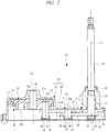
- Figs. 1 and 2 show the wiper motor 10 when the wiper member is at the stop position and Figs. 3 and 4 show the wiper motor 10 when the wiper member is at the reverse position.
- Fig. 3 is a diagram showing a wiper motor at reverse position and Fig. 4 is a cross-sectional diagram along the line B-B in Fig.3 .
- Fig. 5 is a diagram showing inside a gear frame.
- the gear shaft 44 is located radially outside the worm wheel 35, and the sector gear portion 41a of the motion conversion member 41 is placed opposite the bottom wall 30a of the motion conversion mechanism chamber 30.
- the sector gear portion 41a is slidably abut to the supporting face 37 of the gear frame 21, the arm portion 41b thereof is slidably abut to the other axial end face 35b of the worm wheel 35, and the meshing portion G between the pinion gear 40 and the sector gear portion 41a is supported between the supporting face 37 of the gear frame 21 and the retaining plate 42.
- the present invention is not limited to the above embodiment, and can be modified variously without departing from the scope of the present invention.
- the example that the sliding contact members 45 with a cap-like shape are loaded to the output shaft 28, the connecting shaft 43, and the gear shaft 44 individually has been shown, but the present invention is not limited to this example. Since a distance between the output shaft 28 and the gear shaft 44 is constant regardless of the drive of the wiper motor 10, it is also possible to integrate the sliding contact members 45 attached individually to the respective shafts 28 and 44 as one piece.
- a cover member (not shown) of a type covering the retaining plate 42 retaining the respective shafts 28 and 44 is set up, and the sliding contact members 45 corresponding to the respective shafts 28 and 44 are integrated with the cover member.
- the sliding contact members 45 can be loaded on the respective shafts 28 and 44 at once and the procedure of assembly of the wiper motor 10 can be simplified.
- a motor body 11 is not limited to the brushed motor and other electric motors such as a brushless motor can be used.
- the wiper motor 10 of the present invention is not limited to one applied to a rear window of vehicles such as an automobile, and applies to a wiper device applied to airplanes and ships.
- a wiper motor is applied to driving a wiper members forming wiper device set up in a vehicle such as an automobile and to wiping window glasses.
Landscapes
- Engineering & Computer Science (AREA)
- Mechanical Engineering (AREA)
- General Engineering & Computer Science (AREA)
- Power Engineering (AREA)
- Connection Of Motors, Electrical Generators, Mechanical Devices, And The Like (AREA)
- Gear Transmission (AREA)
- Transmission Devices (AREA)
Claims (3)
- Wischermotor (10), der einen Elektromotor (11) und einen Bewegungsumwandlungsmechanismus (29) umfasst, der eine Drehbewegung des Elektromotors in eine Schwenkbewegung umwandelt und die Schwenkbewegung auf eine Ausgangswelle (28) überträgt, umfassend:einen Drehzahlreduktionsmechanismus (26), der eine durch den Elektromotor gedrehte Schnecke (23) und ein mit der Schnecke in Eingriff stehendes Schneckenrad (35) umfasst, wobei der Drehzahlreduktionsmechanismus die Drehzahl des Elektromotors reduziert und die Drehzahl auf den Bewegungsumwandlungsmechanismus überträgt;einen unteren Getrieberahmen (21), der an dem Elektromotor angebracht ist und mit einer Drehzahlreduktionsmechanismuskammer (27), die den Drehzahlreduktionsmechanismus beherbergt, und einer Bewegungsumwandlungskammer (30), die den Bewegungsumwandlungsmechanismus beherbergt, ausgebildet ist;eine Auflagefläche (37), die mit einer axialen Stirnfläche (35b) des Schneckenrades bündig ist, das drehbar in der Kammer des Drehzahlreduktionsmechanismus enthalten ist, und die an einer Bodenwand (30a) der Kammer des Bewegungsumwandlungsmechanismus ausgebildet ist;einen Getriebedeckel (24), der eine Öffnung des Getrieberahmens verschließt;ein Ritzelzahnrad (40), das an einem proximalen Ende der Ausgangswelle befestigt ist, gleitend auf die Auflagefläche des Getrieberahmens gesetzt ist und sich integral mit der Ausgangswelle dreht;ein Bewegungsumwandlungselement (41), das einen Sektorzahnradabschnitt (41a) umfasst, der mit dem Ritzelzahnrad in Eingriff steht, drehbar mit dem Schneckenrad an einer Position verbunden ist, die radial von einer axialen Mitte des Schneckenrades abweicht, und gleitend auf die Auflagefläche des Getrieberahmens und die axiale Stirnfläche des Schneckenrades gesetzt ist; undeine Halteplatte (42), die eine Getriebewelle (44), die in einer axialen Mitte des Sektorzahnradabschnitts vorgesehen ist, und die Ausgangswelle schwenkbar miteinander verbindet,dadurch gekennzeichnet, dass:die Auflagefläche des Getrieberahmens über eine gesamte dem Ritzelrad und dem Bewegungsumwandlungselement zugewandte Fläche der Bodenwand der Bewegungsumwandlungsmechanismuskammer gebildet ist, unddas Ritzelzahnrad und das Bewegungsumwandlungselement über eine gesamte der Auflagefläche des Getrieberahmens zugewandte Fläche gleiten.
- Wischermotor nach Anspruch 1, wobei die Halteplatte näher an der Öffnung des Getrieberahmens als das Ritzelzahnrad und das Bewegungsumwandlungselement angeordnet ist und gleitend auf das Ritzelzahnrad und das Bewegungsumwandlungselement an einer Anlagefläche parallel zur Auflagefläche gesetzt ist.
- Wischermotor nach Anspruch 1, ferner umfassend eine Verbindungswelle (43), die das Schneckenrad und das Bewegungsumwandlungselement an einer Position, die radial von der axialen Mitte des Schneckenrades abweicht, drehbar verbindet und an einem Gleitkontaktelement (45) angebracht ist, das gleitend auf eine Innenfläche des Getriebedeckels an einem proximalen Ende der Verbindungswelle, der Getriebewelle und der Ausgangswelle gesetzt ist.
Applications Claiming Priority (2)
| Application Number | Priority Date | Filing Date | Title |
|---|---|---|---|
| JP2010196536 | 2010-09-02 | ||
| PCT/JP2011/069069 WO2012029608A1 (ja) | 2010-09-02 | 2011-08-24 | ワイパモータ |
Publications (3)
| Publication Number | Publication Date |
|---|---|
| EP2597332A1 EP2597332A1 (de) | 2013-05-29 |
| EP2597332A4 EP2597332A4 (de) | 2017-11-15 |
| EP2597332B1 true EP2597332B1 (de) | 2019-03-06 |
Family
ID=45772701
Family Applications (1)
| Application Number | Title | Priority Date | Filing Date |
|---|---|---|---|
| EP11821625.8A Not-in-force EP2597332B1 (de) | 2010-09-02 | 2011-08-24 | Scheibenwischermotor |
Country Status (6)
| Country | Link |
|---|---|
| US (1) | US9712018B2 (de) |
| EP (1) | EP2597332B1 (de) |
| JP (1) | JP5766193B2 (de) |
| CN (1) | CN103081309B (de) |
| ES (1) | ES2728469T3 (de) |
| WO (1) | WO2012029608A1 (de) |
Families Citing this family (9)
| Publication number | Priority date | Publication date | Assignee | Title |
|---|---|---|---|---|
| JP6106480B2 (ja) * | 2013-03-22 | 2017-03-29 | 株式会社ミツバ | ワイパモータ |
| CN105041998A (zh) * | 2015-06-19 | 2015-11-11 | 江南大学 | 一种偏心轮-扇形连杆直线往复机构 |
| CN106555534A (zh) * | 2015-09-30 | 2017-04-05 | 德昌电机(深圳)有限公司 | 驱动机构、车窗驱动机构及使用该车窗驱动机构的车辆 |
| DE102015122094A1 (de) * | 2015-12-17 | 2017-06-22 | Valeo Systèmes d'Essuyage | Wischermotor und Verfahren zum Herstellen eines Wischermotors |
| GB2545754B (en) * | 2015-12-21 | 2020-10-28 | Tata Motors European Technical Ct Plc | Apparatus for powering windscreen wipers |
| JP6759158B2 (ja) * | 2017-06-15 | 2020-09-23 | 株式会社ミツバ | 減速機構付モータ |
| JP7056162B2 (ja) * | 2018-01-17 | 2022-04-19 | 株式会社デンソー | 減速機構付モータ |
| JP7231455B2 (ja) * | 2019-03-26 | 2023-03-01 | 株式会社ミツバ | 運動変換機構、モータ、及びワイパモータ |
| CN110165828B (zh) * | 2019-06-19 | 2020-12-11 | 湖南奥通工控科技有限公司 | 一种伺服电机 |
Family Cites Families (9)
| Publication number | Priority date | Publication date | Assignee | Title |
|---|---|---|---|---|
| DE4219480A1 (de) * | 1992-06-13 | 1993-12-23 | Swf Auto Electric Gmbh | Antriebsvorrichtung eines Scheibenwischers für ein Kraftfahrzeug |
| US5841249A (en) * | 1995-04-28 | 1998-11-24 | Ut Automotive Dearborn, Inc. | Multi-functional apparatus employing an intermittent motion mechanism |
| JP3607400B2 (ja) * | 1996-02-19 | 2005-01-05 | アスモ株式会社 | モータ装置 |
| US5907885A (en) * | 1997-10-09 | 1999-06-01 | Ut Automotive Dearborn, Inc. | Multi-functional apparatus for use in an automotive vehicle employing multiple tracks |
| JP3550049B2 (ja) | 1999-05-26 | 2004-08-04 | アスモ株式会社 | モータ装置及び車両用ワイパ装置 |
| JP4319597B2 (ja) * | 2003-11-07 | 2009-08-26 | アスモ株式会社 | モータ装置、及びワイパモータ |
| JP4495559B2 (ja) | 2004-09-21 | 2010-07-07 | 株式会社ミツバ | ワイパモータ |
| JP4815216B2 (ja) * | 2006-01-11 | 2011-11-16 | 株式会社ミツバ | ワイパモータ |
| CN201113662Y (zh) * | 2007-09-19 | 2008-09-10 | 林建光 | 内置传杆式刮水电机 |
-
2011
- 2011-08-24 ES ES11821625T patent/ES2728469T3/es active Active
- 2011-08-24 US US13/819,798 patent/US9712018B2/en active Active
- 2011-08-24 WO PCT/JP2011/069069 patent/WO2012029608A1/ja not_active Ceased
- 2011-08-24 EP EP11821625.8A patent/EP2597332B1/de not_active Not-in-force
- 2011-08-24 CN CN201180042316.1A patent/CN103081309B/zh active Active
- 2011-08-24 JP JP2012531818A patent/JP5766193B2/ja active Active
Non-Patent Citations (1)
| Title |
|---|
| None * |
Also Published As
| Publication number | Publication date |
|---|---|
| ES2728469T3 (es) | 2019-10-24 |
| US9712018B2 (en) | 2017-07-18 |
| JPWO2012029608A1 (ja) | 2013-10-28 |
| US20130154412A1 (en) | 2013-06-20 |
| JP5766193B2 (ja) | 2015-08-19 |
| CN103081309B (zh) | 2016-01-20 |
| WO2012029608A1 (ja) | 2012-03-08 |
| CN103081309A (zh) | 2013-05-01 |
| EP2597332A4 (de) | 2017-11-15 |
| EP2597332A1 (de) | 2013-05-29 |
Similar Documents
| Publication | Publication Date | Title |
|---|---|---|
| EP2597332A1 (de) | Scheibenwischermotor | |
| US9182020B2 (en) | Wiper motor | |
| JP6608387B2 (ja) | 減速機構付モータ | |
| JP2012137114A (ja) | 減速機構付モータ | |
| JP2010124621A (ja) | 減速機構付モータ | |
| CN110753804B (zh) | 带减速机构的马达 | |
| EP2597760B1 (de) | Scheibenwischermotor | |
| JP2011259567A (ja) | 減速機構付モータ | |
| JP2011255769A (ja) | ワイパモータ | |
| JP6106480B2 (ja) | ワイパモータ | |
| JP2011256932A (ja) | ワイパモータ | |
| JP5129726B2 (ja) | 減速機構付モータ | |
| JP2010124620A (ja) | 減速機構付モータ | |
| JP5649381B2 (ja) | ワイパモータ | |
| JP2011084251A (ja) | ワイパモータ | |
| JP6759363B2 (ja) | 減速機構付モータ | |
| JP2012060750A (ja) | 減速機構付モータ | |
| JP6670953B2 (ja) | 減速機構付モータ | |
| JP2007259605A (ja) | 減速機構付モータ | |
| JP2011084252A (ja) | ワイパモータ | |
| JP2012135183A (ja) | 減速機構付モータ | |
| JP2020034038A (ja) | モータ装置 |
Legal Events
| Date | Code | Title | Description |
|---|---|---|---|
| PUAI | Public reference made under article 153(3) epc to a published international application that has entered the european phase |
Free format text: ORIGINAL CODE: 0009012 |
|
| 17P | Request for examination filed |
Effective date: 20130220 |
|
| AK | Designated contracting states |
Kind code of ref document: A1 Designated state(s): AL AT BE BG CH CY CZ DE DK EE ES FI FR GB GR HR HU IE IS IT LI LT LU LV MC MK MT NL NO PL PT RO RS SE SI SK SM TR |
|
| DAX | Request for extension of the european patent (deleted) | ||
| RA4 | Supplementary search report drawn up and despatched (corrected) |
Effective date: 20171018 |
|
| RIC1 | Information provided on ipc code assigned before grant |
Ipc: H02K 7/116 20060101ALI20171012BHEP Ipc: F16H 57/02 20120101ALI20171012BHEP Ipc: F16H 1/16 20060101AFI20171012BHEP Ipc: F16H 21/40 20060101ALI20171012BHEP Ipc: B60S 1/08 20060101ALI20171012BHEP |
|
| GRAP | Despatch of communication of intention to grant a patent |
Free format text: ORIGINAL CODE: EPIDOSNIGR1 |
|
| STAA | Information on the status of an ep patent application or granted ep patent |
Free format text: STATUS: GRANT OF PATENT IS INTENDED |
|
| INTG | Intention to grant announced |
Effective date: 20180927 |
|
| GRAS | Grant fee paid |
Free format text: ORIGINAL CODE: EPIDOSNIGR3 |
|
| GRAA | (expected) grant |
Free format text: ORIGINAL CODE: 0009210 |
|
| STAA | Information on the status of an ep patent application or granted ep patent |
Free format text: STATUS: THE PATENT HAS BEEN GRANTED |
|
| AK | Designated contracting states |
Kind code of ref document: B1 Designated state(s): AL AT BE BG CH CY CZ DE DK EE ES FI FR GB GR HR HU IE IS IT LI LT LU LV MC MK MT NL NO PL PT RO RS SE SI SK SM TR |
|
| REG | Reference to a national code |
Ref country code: GB Ref legal event code: FG4D |
|
| REG | Reference to a national code |
Ref country code: CH Ref legal event code: EP Ref country code: AT Ref legal event code: REF Ref document number: 1104981 Country of ref document: AT Kind code of ref document: T Effective date: 20190315 |
|
| REG | Reference to a national code |
Ref country code: DE Ref legal event code: R096 Ref document number: 602011056950 Country of ref document: DE |
|
| REG | Reference to a national code |
Ref country code: IE Ref legal event code: FG4D |
|
| REG | Reference to a national code |
Ref country code: NL Ref legal event code: MP Effective date: 20190306 |
|
| REG | Reference to a national code |
Ref country code: LT Ref legal event code: MG4D |
|
| PG25 | Lapsed in a contracting state [announced via postgrant information from national office to epo] |
Ref country code: SE Free format text: LAPSE BECAUSE OF FAILURE TO SUBMIT A TRANSLATION OF THE DESCRIPTION OR TO PAY THE FEE WITHIN THE PRESCRIBED TIME-LIMIT Effective date: 20190306 Ref country code: FI Free format text: LAPSE BECAUSE OF FAILURE TO SUBMIT A TRANSLATION OF THE DESCRIPTION OR TO PAY THE FEE WITHIN THE PRESCRIBED TIME-LIMIT Effective date: 20190306 Ref country code: NO Free format text: LAPSE BECAUSE OF FAILURE TO SUBMIT A TRANSLATION OF THE DESCRIPTION OR TO PAY THE FEE WITHIN THE PRESCRIBED TIME-LIMIT Effective date: 20190606 Ref country code: LT Free format text: LAPSE BECAUSE OF FAILURE TO SUBMIT A TRANSLATION OF THE DESCRIPTION OR TO PAY THE FEE WITHIN THE PRESCRIBED TIME-LIMIT Effective date: 20190306 |
|
| PG25 | Lapsed in a contracting state [announced via postgrant information from national office to epo] |
Ref country code: BG Free format text: LAPSE BECAUSE OF FAILURE TO SUBMIT A TRANSLATION OF THE DESCRIPTION OR TO PAY THE FEE WITHIN THE PRESCRIBED TIME-LIMIT Effective date: 20190606 Ref country code: GR Free format text: LAPSE BECAUSE OF FAILURE TO SUBMIT A TRANSLATION OF THE DESCRIPTION OR TO PAY THE FEE WITHIN THE PRESCRIBED TIME-LIMIT Effective date: 20190607 Ref country code: HR Free format text: LAPSE BECAUSE OF FAILURE TO SUBMIT A TRANSLATION OF THE DESCRIPTION OR TO PAY THE FEE WITHIN THE PRESCRIBED TIME-LIMIT Effective date: 20190306 Ref country code: NL Free format text: LAPSE BECAUSE OF FAILURE TO SUBMIT A TRANSLATION OF THE DESCRIPTION OR TO PAY THE FEE WITHIN THE PRESCRIBED TIME-LIMIT Effective date: 20190306 Ref country code: LV Free format text: LAPSE BECAUSE OF FAILURE TO SUBMIT A TRANSLATION OF THE DESCRIPTION OR TO PAY THE FEE WITHIN THE PRESCRIBED TIME-LIMIT Effective date: 20190306 Ref country code: RS Free format text: LAPSE BECAUSE OF FAILURE TO SUBMIT A TRANSLATION OF THE DESCRIPTION OR TO PAY THE FEE WITHIN THE PRESCRIBED TIME-LIMIT Effective date: 20190306 |
|
| REG | Reference to a national code |
Ref country code: AT Ref legal event code: MK05 Ref document number: 1104981 Country of ref document: AT Kind code of ref document: T Effective date: 20190306 |
|
| REG | Reference to a national code |
Ref country code: ES Ref legal event code: FG2A Ref document number: 2728469 Country of ref document: ES Kind code of ref document: T3 Effective date: 20191024 |
|
| PG25 | Lapsed in a contracting state [announced via postgrant information from national office to epo] |
Ref country code: IT Free format text: LAPSE BECAUSE OF FAILURE TO SUBMIT A TRANSLATION OF THE DESCRIPTION OR TO PAY THE FEE WITHIN THE PRESCRIBED TIME-LIMIT Effective date: 20190306 Ref country code: RO Free format text: LAPSE BECAUSE OF FAILURE TO SUBMIT A TRANSLATION OF THE DESCRIPTION OR TO PAY THE FEE WITHIN THE PRESCRIBED TIME-LIMIT Effective date: 20190306 Ref country code: SK Free format text: LAPSE BECAUSE OF FAILURE TO SUBMIT A TRANSLATION OF THE DESCRIPTION OR TO PAY THE FEE WITHIN THE PRESCRIBED TIME-LIMIT Effective date: 20190306 Ref country code: CZ Free format text: LAPSE BECAUSE OF FAILURE TO SUBMIT A TRANSLATION OF THE DESCRIPTION OR TO PAY THE FEE WITHIN THE PRESCRIBED TIME-LIMIT Effective date: 20190306 Ref country code: EE Free format text: LAPSE BECAUSE OF FAILURE TO SUBMIT A TRANSLATION OF THE DESCRIPTION OR TO PAY THE FEE WITHIN THE PRESCRIBED TIME-LIMIT Effective date: 20190306 Ref country code: AL Free format text: LAPSE BECAUSE OF FAILURE TO SUBMIT A TRANSLATION OF THE DESCRIPTION OR TO PAY THE FEE WITHIN THE PRESCRIBED TIME-LIMIT Effective date: 20190306 Ref country code: PT Free format text: LAPSE BECAUSE OF FAILURE TO SUBMIT A TRANSLATION OF THE DESCRIPTION OR TO PAY THE FEE WITHIN THE PRESCRIBED TIME-LIMIT Effective date: 20190706 |
|
| PG25 | Lapsed in a contracting state [announced via postgrant information from national office to epo] |
Ref country code: PL Free format text: LAPSE BECAUSE OF FAILURE TO SUBMIT A TRANSLATION OF THE DESCRIPTION OR TO PAY THE FEE WITHIN THE PRESCRIBED TIME-LIMIT Effective date: 20190306 Ref country code: SM Free format text: LAPSE BECAUSE OF FAILURE TO SUBMIT A TRANSLATION OF THE DESCRIPTION OR TO PAY THE FEE WITHIN THE PRESCRIBED TIME-LIMIT Effective date: 20190306 |
|
| REG | Reference to a national code |
Ref country code: DE Ref legal event code: R097 Ref document number: 602011056950 Country of ref document: DE |
|
| PG25 | Lapsed in a contracting state [announced via postgrant information from national office to epo] |
Ref country code: AT Free format text: LAPSE BECAUSE OF FAILURE TO SUBMIT A TRANSLATION OF THE DESCRIPTION OR TO PAY THE FEE WITHIN THE PRESCRIBED TIME-LIMIT Effective date: 20190306 Ref country code: IS Free format text: LAPSE BECAUSE OF FAILURE TO SUBMIT A TRANSLATION OF THE DESCRIPTION OR TO PAY THE FEE WITHIN THE PRESCRIBED TIME-LIMIT Effective date: 20190706 |
|
| PLBE | No opposition filed within time limit |
Free format text: ORIGINAL CODE: 0009261 |
|
| STAA | Information on the status of an ep patent application or granted ep patent |
Free format text: STATUS: NO OPPOSITION FILED WITHIN TIME LIMIT |
|
| PG25 | Lapsed in a contracting state [announced via postgrant information from national office to epo] |
Ref country code: DK Free format text: LAPSE BECAUSE OF FAILURE TO SUBMIT A TRANSLATION OF THE DESCRIPTION OR TO PAY THE FEE WITHIN THE PRESCRIBED TIME-LIMIT Effective date: 20190306 |
|
| 26N | No opposition filed |
Effective date: 20191209 |
|
| PG25 | Lapsed in a contracting state [announced via postgrant information from national office to epo] |
Ref country code: SI Free format text: LAPSE BECAUSE OF FAILURE TO SUBMIT A TRANSLATION OF THE DESCRIPTION OR TO PAY THE FEE WITHIN THE PRESCRIBED TIME-LIMIT Effective date: 20190306 |
|
| PG25 | Lapsed in a contracting state [announced via postgrant information from national office to epo] |
Ref country code: TR Free format text: LAPSE BECAUSE OF FAILURE TO SUBMIT A TRANSLATION OF THE DESCRIPTION OR TO PAY THE FEE WITHIN THE PRESCRIBED TIME-LIMIT Effective date: 20190306 |
|
| GBPC | Gb: european patent ceased through non-payment of renewal fee |
Effective date: 20190824 |
|
| PG25 | Lapsed in a contracting state [announced via postgrant information from national office to epo] |
Ref country code: LI Free format text: LAPSE BECAUSE OF NON-PAYMENT OF DUE FEES Effective date: 20190831 Ref country code: MC Free format text: LAPSE BECAUSE OF FAILURE TO SUBMIT A TRANSLATION OF THE DESCRIPTION OR TO PAY THE FEE WITHIN THE PRESCRIBED TIME-LIMIT Effective date: 20190306 Ref country code: LU Free format text: LAPSE BECAUSE OF NON-PAYMENT OF DUE FEES Effective date: 20190824 Ref country code: CH Free format text: LAPSE BECAUSE OF NON-PAYMENT OF DUE FEES Effective date: 20190831 |
|
| REG | Reference to a national code |
Ref country code: BE Ref legal event code: MM Effective date: 20190831 |
|
| PG25 | Lapsed in a contracting state [announced via postgrant information from national office to epo] |
Ref country code: IE Free format text: LAPSE BECAUSE OF NON-PAYMENT OF DUE FEES Effective date: 20190824 |
|
| PG25 | Lapsed in a contracting state [announced via postgrant information from national office to epo] |
Ref country code: BE Free format text: LAPSE BECAUSE OF NON-PAYMENT OF DUE FEES Effective date: 20190831 Ref country code: GB Free format text: LAPSE BECAUSE OF NON-PAYMENT OF DUE FEES Effective date: 20190824 |
|
| PGFP | Annual fee paid to national office [announced via postgrant information from national office to epo] |
Ref country code: DE Payment date: 20200812 Year of fee payment: 10 Ref country code: FR Payment date: 20200715 Year of fee payment: 10 Ref country code: ES Payment date: 20200901 Year of fee payment: 10 |
|
| PG25 | Lapsed in a contracting state [announced via postgrant information from national office to epo] |
Ref country code: CY Free format text: LAPSE BECAUSE OF FAILURE TO SUBMIT A TRANSLATION OF THE DESCRIPTION OR TO PAY THE FEE WITHIN THE PRESCRIBED TIME-LIMIT Effective date: 20190306 |
|
| PG25 | Lapsed in a contracting state [announced via postgrant information from national office to epo] |
Ref country code: HU Free format text: LAPSE BECAUSE OF FAILURE TO SUBMIT A TRANSLATION OF THE DESCRIPTION OR TO PAY THE FEE WITHIN THE PRESCRIBED TIME-LIMIT; INVALID AB INITIO Effective date: 20110824 Ref country code: MT Free format text: LAPSE BECAUSE OF FAILURE TO SUBMIT A TRANSLATION OF THE DESCRIPTION OR TO PAY THE FEE WITHIN THE PRESCRIBED TIME-LIMIT Effective date: 20190306 |
|
| REG | Reference to a national code |
Ref country code: DE Ref legal event code: R119 Ref document number: 602011056950 Country of ref document: DE |
|
| PG25 | Lapsed in a contracting state [announced via postgrant information from national office to epo] |
Ref country code: MK Free format text: LAPSE BECAUSE OF FAILURE TO SUBMIT A TRANSLATION OF THE DESCRIPTION OR TO PAY THE FEE WITHIN THE PRESCRIBED TIME-LIMIT Effective date: 20190306 |
|
| PG25 | Lapsed in a contracting state [announced via postgrant information from national office to epo] |
Ref country code: FR Free format text: LAPSE BECAUSE OF NON-PAYMENT OF DUE FEES Effective date: 20210831 Ref country code: DE Free format text: LAPSE BECAUSE OF NON-PAYMENT OF DUE FEES Effective date: 20220301 |
|
| REG | Reference to a national code |
Ref country code: ES Ref legal event code: FD2A Effective date: 20221103 |
|
| PG25 | Lapsed in a contracting state [announced via postgrant information from national office to epo] |
Ref country code: ES Free format text: LAPSE BECAUSE OF NON-PAYMENT OF DUE FEES Effective date: 20210825 |