EP2597338A2 - Schaltsteuerungsvorrichtung für stufenloses Getriebe - Google Patents
Schaltsteuerungsvorrichtung für stufenloses Getriebe Download PDFInfo
- Publication number
- EP2597338A2 EP2597338A2 EP12193972.2A EP12193972A EP2597338A2 EP 2597338 A2 EP2597338 A2 EP 2597338A2 EP 12193972 A EP12193972 A EP 12193972A EP 2597338 A2 EP2597338 A2 EP 2597338A2
- Authority
- EP
- European Patent Office
- Prior art keywords
- shift
- driver
- acceleration
- speed
- mode
- Prior art date
- Legal status (The legal status is an assumption and is not a legal conclusion. Google has not performed a legal analysis and makes no representation as to the accuracy of the status listed.)
- Withdrawn
Links
Images




Classifications
-
- F—MECHANICAL ENGINEERING; LIGHTING; HEATING; WEAPONS; BLASTING
- F16—ENGINEERING ELEMENTS AND UNITS; GENERAL MEASURES FOR PRODUCING AND MAINTAINING EFFECTIVE FUNCTIONING OF MACHINES OR INSTALLATIONS; THERMAL INSULATION IN GENERAL
- F16H—GEARING
- F16H61/00—Control functions within control units of change-speed- or reversing-gearings for conveying rotary motion ; Control of exclusively fluid gearing, friction gearing, gearings with endless flexible members or other particular types of gearing
- F16H61/02—Control functions within control units of change-speed- or reversing-gearings for conveying rotary motion ; Control of exclusively fluid gearing, friction gearing, gearings with endless flexible members or other particular types of gearing characterised by the signals used
-
- F—MECHANICAL ENGINEERING; LIGHTING; HEATING; WEAPONS; BLASTING
- F16—ENGINEERING ELEMENTS AND UNITS; GENERAL MEASURES FOR PRODUCING AND MAINTAINING EFFECTIVE FUNCTIONING OF MACHINES OR INSTALLATIONS; THERMAL INSULATION IN GENERAL
- F16H—GEARING
- F16H61/00—Control functions within control units of change-speed- or reversing-gearings for conveying rotary motion ; Control of exclusively fluid gearing, friction gearing, gearings with endless flexible members or other particular types of gearing
- F16H61/66—Control functions within control units of change-speed- or reversing-gearings for conveying rotary motion ; Control of exclusively fluid gearing, friction gearing, gearings with endless flexible members or other particular types of gearing specially adapted for continuously variable gearings
-
- F—MECHANICAL ENGINEERING; LIGHTING; HEATING; WEAPONS; BLASTING
- F16—ENGINEERING ELEMENTS AND UNITS; GENERAL MEASURES FOR PRODUCING AND MAINTAINING EFFECTIVE FUNCTIONING OF MACHINES OR INSTALLATIONS; THERMAL INSULATION IN GENERAL
- F16H—GEARING
- F16H59/00—Control inputs to control units of change-speed- or reversing-gearings for conveying rotary motion
- F16H59/14—Inputs being a function of torque or torque demand
- F16H59/18—Inputs being a function of torque or torque demand dependent on the position of the accelerator pedal
-
- F—MECHANICAL ENGINEERING; LIGHTING; HEATING; WEAPONS; BLASTING
- F16—ENGINEERING ELEMENTS AND UNITS; GENERAL MEASURES FOR PRODUCING AND MAINTAINING EFFECTIVE FUNCTIONING OF MACHINES OR INSTALLATIONS; THERMAL INSULATION IN GENERAL
- F16H—GEARING
- F16H59/00—Control inputs to control units of change-speed- or reversing-gearings for conveying rotary motion
- F16H59/36—Inputs being a function of speed
-
- F—MECHANICAL ENGINEERING; LIGHTING; HEATING; WEAPONS; BLASTING
- F16—ENGINEERING ELEMENTS AND UNITS; GENERAL MEASURES FOR PRODUCING AND MAINTAINING EFFECTIVE FUNCTIONING OF MACHINES OR INSTALLATIONS; THERMAL INSULATION IN GENERAL
- F16H—GEARING
- F16H61/00—Control functions within control units of change-speed- or reversing-gearings for conveying rotary motion ; Control of exclusively fluid gearing, friction gearing, gearings with endless flexible members or other particular types of gearing
-
- F—MECHANICAL ENGINEERING; LIGHTING; HEATING; WEAPONS; BLASTING
- F16—ENGINEERING ELEMENTS AND UNITS; GENERAL MEASURES FOR PRODUCING AND MAINTAINING EFFECTIVE FUNCTIONING OF MACHINES OR INSTALLATIONS; THERMAL INSULATION IN GENERAL
- F16H—GEARING
- F16H61/00—Control functions within control units of change-speed- or reversing-gearings for conveying rotary motion ; Control of exclusively fluid gearing, friction gearing, gearings with endless flexible members or other particular types of gearing
- F16H61/66—Control functions within control units of change-speed- or reversing-gearings for conveying rotary motion ; Control of exclusively fluid gearing, friction gearing, gearings with endless flexible members or other particular types of gearing specially adapted for continuously variable gearings
- F16H61/662—Control functions within control units of change-speed- or reversing-gearings for conveying rotary motion ; Control of exclusively fluid gearing, friction gearing, gearings with endless flexible members or other particular types of gearing specially adapted for continuously variable gearings with endless flexible members
- F16H61/66254—Control functions within control units of change-speed- or reversing-gearings for conveying rotary motion ; Control of exclusively fluid gearing, friction gearing, gearings with endless flexible members or other particular types of gearing specially adapted for continuously variable gearings with endless flexible members controlling of shifting being influenced by a signal derived from the engine and the main coupling
-
- F—MECHANICAL ENGINEERING; LIGHTING; HEATING; WEAPONS; BLASTING
- F16—ENGINEERING ELEMENTS AND UNITS; GENERAL MEASURES FOR PRODUCING AND MAINTAINING EFFECTIVE FUNCTIONING OF MACHINES OR INSTALLATIONS; THERMAL INSULATION IN GENERAL
- F16H—GEARING
- F16H61/00—Control functions within control units of change-speed- or reversing-gearings for conveying rotary motion ; Control of exclusively fluid gearing, friction gearing, gearings with endless flexible members or other particular types of gearing
- F16H61/66—Control functions within control units of change-speed- or reversing-gearings for conveying rotary motion ; Control of exclusively fluid gearing, friction gearing, gearings with endless flexible members or other particular types of gearing specially adapted for continuously variable gearings
- F16H61/662—Control functions within control units of change-speed- or reversing-gearings for conveying rotary motion ; Control of exclusively fluid gearing, friction gearing, gearings with endless flexible members or other particular types of gearing specially adapted for continuously variable gearings with endless flexible members
- F16H61/66254—Control functions within control units of change-speed- or reversing-gearings for conveying rotary motion ; Control of exclusively fluid gearing, friction gearing, gearings with endless flexible members or other particular types of gearing specially adapted for continuously variable gearings with endless flexible members controlling of shifting being influenced by a signal derived from the engine and the main coupling
- F16H61/66259—Control functions within control units of change-speed- or reversing-gearings for conveying rotary motion ; Control of exclusively fluid gearing, friction gearing, gearings with endless flexible members or other particular types of gearing specially adapted for continuously variable gearings with endless flexible members controlling of shifting being influenced by a signal derived from the engine and the main coupling using electrical or electronical sensing or control means
-
- F—MECHANICAL ENGINEERING; LIGHTING; HEATING; WEAPONS; BLASTING
- F16—ENGINEERING ELEMENTS AND UNITS; GENERAL MEASURES FOR PRODUCING AND MAINTAINING EFFECTIVE FUNCTIONING OF MACHINES OR INSTALLATIONS; THERMAL INSULATION IN GENERAL
- F16H—GEARING
- F16H61/00—Control functions within control units of change-speed- or reversing-gearings for conveying rotary motion ; Control of exclusively fluid gearing, friction gearing, gearings with endless flexible members or other particular types of gearing
- F16H61/66—Control functions within control units of change-speed- or reversing-gearings for conveying rotary motion ; Control of exclusively fluid gearing, friction gearing, gearings with endless flexible members or other particular types of gearing specially adapted for continuously variable gearings
- F16H61/662—Control functions within control units of change-speed- or reversing-gearings for conveying rotary motion ; Control of exclusively fluid gearing, friction gearing, gearings with endless flexible members or other particular types of gearing specially adapted for continuously variable gearings with endless flexible members
- F16H61/66272—Control functions within control units of change-speed- or reversing-gearings for conveying rotary motion ; Control of exclusively fluid gearing, friction gearing, gearings with endless flexible members or other particular types of gearing specially adapted for continuously variable gearings with endless flexible members characterised by means for controlling the torque transmitting capability of the gearing
Definitions
- the present invention relates to a shift control apparatus of a continuously variable transmission.
- a belt-drive CVT employs a primary variable-width pulley, a secondary variable-width pulley, and a drive belt (i.e., a segmented steel belt) running in the pair of variable-width pulleys.
- the CVT is configured such that torque, inputted from an internal combustion engine to the primary pulley, is transmitted via the drive belt to the secondary pulley, while steplessly varying a transmission ratio (in other words, a torque ratio) by changing the effective diameters of the primary and secondary pulleys.
- a shift control apparatus of the CVT is configured to utilize a shift characteristic diagram stored in a memory of a CVT control unit and set or preprogrammed based on simulations and experiments. Shift control is executed in accordance with a selected one of shift lines (shift patterns) defined by the shift characteristic diagram.
- a target primary-pulley rotational speed is set or determined, based on both the accelerator opening (the accelerator pedal position) and the vehicle speed, from a preprogrammed shift characteristic diagram.
- a target transmission ratio (a target pulley ratio) is determined based on the set target primary-pulley rotational speed.
- shift control is executed by controlling the pulley groove width of each of the primary and secondary pulleys so that the actual pulley groove widths of the primary and secondary pulleys are brought into respective target pulley groove widths, corresponding to the determined target transmission ratio.
- a CVT control unit is configured to determine, based on a driver's accelerator-pedal operation or a driver's accelerator manipulated variable (e.g., an accelerator pedal position changed by the driver and/or a driver's accelerator depression speed), whether or not there is a driver's intention to accelerate.
- a driver's accelerator manipulated variable e.g., an accelerator pedal position changed by the driver and/or a driver's accelerator depression speed
- a target transmission ratio is set or determined based on the shift line suited for vehicle acceleration.
- a shift control apparatus of a continuously variable transmission configured to determine a demanded degree of a driver's intention to accelerate an automotive vehicle, thereby avoiding a sudden unpleasant feeling caused by an undesirably bigger downshift.
- a shift control apparatus of a continuously variable transmission configured to steplessly vary a torque inputted from an engine to an input rotating member and configured to transmit the steplessly-varied torque to an output rotating member, comprises an acceleration intention determination section for determining whether a driver's acceleration intention is present or absent, a shift mode setting section for setting a shift-control mode of the continuously variable transmission to an acceleration mode in which a target rotational speed of the input rotating member is set to a higher rotational speed than that of a normal mode, when it has been determined that the driver's acceleration intention is present, a target transmission ratio setting section for setting a target transmission ratio based on an accelerator opening and a vehicle speed from a map provided for each of the normal mode and the acceleration mode, a shift speed setting section for setting a shift speed based on the target transmission ratio and the vehicle speed, a shift control section for controlling a shift of the continuously variable transmission based on at least the target transmission ratio and the shift speed set by the shift speed setting section, and
- Continuously variable transmission 10 employs a primary variable-width pulley 11, a secondary variable-width pulley 12, a drive belt (i.e., a segmented steel belt) 13 running in the pair of variable-width pulleys 11-12, a CVT control unit 20, and a hydraulic control unit 30.
- the rotation axis of primary pulley 11 is arranged coaxially with the axis of a crankshaft of an internal combustion engine 1.
- a torque converter 2 and a forward/reverse (F/R) changeover mechanism 3 are arranged in that order from the side of engine 1 and installed between the engine 1 and the primary pulley 11.
- Torque converter 2 is equipped with a pump impeller 2a connected to the output shaft (the crankshaft) of engine 1, a turbine runner 2b connected to the input shaft of F/R changeover mechanism 3, a stator 2c, and a lockup clutch 2d.
- F/R changeover mechanism 3 is mainly comprised of a double-pinion planetary gearset 3a.
- a sun gear of double-pinion planetary gearset 3a is connected to the turbine runner 2b of torque converter 2, while a carrier of double-pinion planetary gearset 3a is connected to the primary pulley 11.
- F/R changeover mechanism 3 is further equipped with a start-up clutch 3b provided for direct-coupling of the sun gear and the carrier of double-pinion planetary gearset 3a, and a reverse brake 3c provided for holding a ring gear of double-pinion planetary gearset 3a stationary.
- Primary pulley 11 is an input-shaft side pulley (a driving pulley) for inputting rotation of the engine 1 to the CVT 10.
- Primary pulley 11 is equipped with a stationary conical flange 11b configured to be rotatable together with an input shaft 11d and a movable conical flange 11a configured to axially displaceable (slidable) by hydraulic pressure (i.e., a primary pressure Ppri) applied to a primary-pulley actuation cylinder chamber 11c.
- the movable flange 11a and the stationary flange 11b are arranged to be axially opposed to each other so as to form a V-shaped pulley groove whose width can be changed depending on the axial position of the movable flange 11a relative to the stationary flange 11b.
- driving torque is transmitted from the engine 1 through the torque converter 2 via the F/R changeover mechanism 3 to the primary pulley 11.
- a rotational speed Npri of primary pulley 11 is detected by means of a primary-pulley rotational speed sensor 26.
- Secondary pulley 12 is an output-side pulley (a driven pulley.
- Secondary pulley 12 is equipped with a stationary conical flange 12b configured to be rotatable together with an output shaft 12d and a movable conical flange 12a configured to axially displaceable (slidable) by hydraulic pressure (i.e., a secondary pressure Psec) applied to a secondary-pulley actuation cylinder chamber 12c.
- the movable flange 12a and the stationary flange 12b are arranged to be axially opposed to each other so as to form a V-shaped pulley groove whose width can be changed depending on the axial position of the movable flange 12a relative to the stationary flange 12b.
- a secondary pressure Psec hydraulic pressure
- secondary pulley 12 is connected through gear and shaft components 14 (involving an idler gear and shaft and a countershaft and gear assembly) to a differential 4.
- Rotation (torque) transmitted from the primary pulley 11 through the drive belt 13 to the secondary pulley 12 is outputted to the differential 4.
- a rotational speed Nsec of secondary pulley 12 is detected by means of a secondary-pulley rotational speed sensor 27.
- Drive belt 13, running in the primary and secondary pulleys 11-12, is provided to transmit rotation of the primary pulley 11 to the secondary pulley 12.
- a segmented steel belt is generally used as the drive belt 13.
- the drive belt 13 is a "push belt” differing from a conventional V-belt configured to transmit torque by tension. That is, the drive belt 13 is configured to transmit torque by compression.
- CVT control unit 20 is configured to determine a target transmission ratio (a target pulley ratio) and a belt contact pressure of the drive belt 13, and also configured to send command signals, corresponding to the determined target pulley ratio and belt contact pressure, to the hydraulic control unit 30 for controlling the CVT 10.
- the pulley ratio is a ratio of the effective radius of the secondary pulley 12 and the effective radius of the primary pulley 11, that is, a fraction obtained by dividing the effective radius of the secondary pulley 12 by the effective radius of the primary pulley 11.
- the pulley ratio is synonymous with a transmission ratio.
- CVT control unit 20 is further configured to send a command to the hydraulic control unit 30 for friction-element control of friction elements of F/R changeover mechanism 3 (i.e., engagement/disengagement control of start-up clutch 3b and application/release control of reverse brake 3c) and for engagement/disengagement control of lockup clutch 2d of torque converter 2.
- friction-element control of friction elements of F/R changeover mechanism 3 i.e., engagement/disengagement control of start-up clutch 3b and application/release control of reverse brake 3c
- Hydraulic control unit 30 is configured to control, responsively to a command from CVT control unit 20, both hydraulic pressure (i.e., primary pressure Ppri) applied to the primary-pulley actuation cylinder chamber 11c and hydraulic pressure (i.e., secondary pressure Psec) applied to the secondary-pulley actuation cylinder chamber 12c.
- hydraulic pressure i.e., primary pressure Ppri
- secondary pressure Psec hydraulic pressure
- the movable flange 11a axially slides along its rotation axis so that the axial position of movable flange 11a is determined depending on the primary pressure Ppri, while the movable flange 12a axially slides along its rotation axis so that the axial position of movable flange 12a is determined depending on the secondary pressure Psec.
- Hydraulic control unit 30 is further configured to control, responsively to a command from CVT control unit 20, hydraulic pressure Pc to be supplied to F/R changeover mechanism 3, for engagement/disengagement control of start-up clutch 3b and application/release control of reverse brake 3c.
- CVT control unit 20 generally comprises a microcomputer.
- CVT control unit 20 includes an input/output interface (I/O), memories (RAM, ROM), and a microprocessor or a central processing unit (CPU).
- the input/output interface (I/O) of CVT control unit 20 receives input information from various engine/vehicle sensors and engine control unit 21, more concretely, an accelerator manipulated variable sensor 23, the primary-pulley rotational speed sensor 26, the secondary-pulley rotational speed sensor 27, and two hydraulic pressure sensors 29a-29b.
- Engine control unit 21 is configured to output information about torque, inputted from the engine 1 to the CVT 10, to the CVT control unit 20.
- Accelerator manipulated variable sensor 23 is configured to output informational data signals, indicating an accelerator manipulated variable (i.e., accelerator opening To or an accelerator pedal position) and a time rate-of-change (dTo/dt) in the detected accelerator manipulated variable To (that is, accelerator depression speed Tv), to the CVT control unit 20.
- an accelerator manipulated variable i.e., accelerator opening To or an accelerator pedal position
- dTo/dt time rate-of-change
- Primary-pulley rotational speed sensor 26 is configured to output a primary-pulley speed signal, indicating the rotational speed Npri of primary pulley 11, to the CVT control unit 20.
- secondary-pulley rotational speed sensor 27 is configured to output a secondary-pulley speed signal, indicating the rotational speed Nsec of secondary pulley 12, to the CVT control unit 20.
- the central processing unit allows the access by the I/O interface of input informational data signals from the previously-discussed engine/vehicle sensors and the engine control unit 21.
- CVT control unit 20 is configured to calculate, based on both the primary-pulley speed signal Npri and the secondary-pulley speed signal Nsec, an actual pulley ratio (Npri/Nsec), in other words, an actual speed ratio (Nsec/Npri).
- CVT control unit 20 is further configured to estimate or specify a velocity of the automotive vehicle (i.e., a vehicle speed V) on the basis of the secondary-pulley speed signal Nsec.
- Hydraulic pressure sensor 29a is configured to output a primary-pressure signal, indicating the hydraulic pressure (i.e., the primary pressure Ppri) applied to primary-pulley actuation cylinder chamber 11c, to the CVT control unit 20.
- hydraulic pressure sensor 29b is configured to output a secondary-pressure signal, indicating the hydraulic pressure (i.e., the secondary pressure Psec) applied to secondary-pulley actuation cylinder chamber 12c, to the CVT control unit 20.
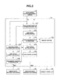
- FIG. 2 there is shown the block diagram of CVT control unit 20.
- CVT control unit 20 is equipped with an acceleration intention determination section 201, a shift mode setting section 202, a target transmission ratio setting section 203, a shift speed setting section 204, a demanded degree determination section 205, an initial downshift completion determination section 206, a shift speed correction section 207, a shift control section 208, and a memory section 209.
- map data which specify the relationship among accelerator opening To, accelerator depression speed Tv, a normal mode, and an acceleration mode, are predefined for every vehicle speeds V.
- the current vehicle speed is estimated from latest up-to-date information about the secondary-pulley rotational speed Nsec.
- the predefined mode determination maps are stored in the memory section 209 of CVT control unit 20.
- Shift mode setting section 202 is configured to set a shift mode of the CVT 10.
- acceleration intention determination section 201 determines that a driver's intention to accelerate is present, a shift mode of the CVT 10 is set to an acceleration mode.
- acceleration intention determination section 201 determines that a driver's intention to accelerate is absent, a shift mode of the CVT 10 is set to a normal mode.
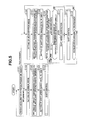
- FIG. 3 there is shown one example of a plurality of mode determination maps stored in the memory section 209 of CVT control unit 20.
- the mode determination map shown in Fig. 3 specifies the relationship among a threshold value for determining a transition from the normal mode to the acceleration mode, a threshold value for determining a transition from the acceleration mode to the normal mode, accelerator opening To, and accelerator depression speed Tv, at any vehicle speed.
- a characteristic curve "A" is a normal-to-acceleration mode-transition determination characteristic curve, which is obtained by plotting threshold values for any accelerator opening To and any accelerator depression speed Tv.
- a characteristic curve "B" is an acceleration-to-normal mode-transition determination characteristic curve, which is obtained by plotting threshold values for any accelerator opening To and any accelerator depression speed Tv.
- acceleration intention determination section 201 determines that a driver's intention to accelerate is present, and thus shift mode setting section 202 sets a shift mode of the CVT 10 to an acceleration mode.
- acceleration intention determination section 201 determines that a driver's intention to accelerate is absent, and thus shift mode setting section 202 maintains the shift mode of the CVT 10 at the normal mode, so that the normal mode remains unchanged.
- shift mode setting section 202 maintains the shift mode of the CVT 10 at the acceleration mode, so that the acceleration mode remains unchanged. Also, when latest up-to-date information (the coordinates) about accelerator opening To and accelerator depression speed Tv has been displaced or transferred to a point "X3" during the acceleration mode, acceleration intention determination section 201 determines that a driver's intention to accelerate is absent, and thus a mode transition from the acceleration mode to the normal mode occurs through the shift mode setting section 202.
- a hysteresis is provided in a mode transition (a mode shift) from one of a normal mode and an acceleration mode to the other (see a width or a difference Ah between the normal-to-acceleration mode-transition determination characteristic curve "A" and the acceleration-to-normal mode-transition determination characteristic curve "B" in Fig. 3 ).
- Target transmission ratio setting section 203 is configured to set or determine, based on latest up-to-date information about accelerator opening To and vehicle speed V, a target primary-pulley rotational speed Nt, from a shift mode map (a shift characteristic diagram) set or selected at the current execution cycle, and also configured to determine a target transmission ratio Rt (i.e., a target pulley ratio) based on the set target primary-pulley rotational speed Nt.
- a target transmission ratio Rt i.e., a target pulley ratio
- the shift mode maps (the shift characteristic diagrams), utilized by target transmission ratio setting section 203 for map-retrieval, are stored in the memory section 209.
- memory section 209 stores both a shift characteristic diagram having shift lines (shift patterns) for the normal mode and a shift characteristic diagram having shift lines (shift patterns) for the acceleration mode.
- Figs. 4A-4B there are shown two different shift characteristic diagrams.
- Fig. 4A shows the shift characteristic diagram for the normal mode
- Fig. 4B shows the shift characteristic diagram for the acceleration mode.
- a plurality of characteristic lines e.g., lines TV1, TV2, TV3, and TV4 in Figs. 4A-4B
- target primary-pulley rotational speed Nt can be determined, based on latest up-to-date information about vehicle speed V and accelerator opening To, from a selected one of the two different shift characteristic diagrams of Figs. 4A-4B .
- target primary-pulley rotational speed Nt of the shift characteristic diagram for the acceleration mode (see Fig. 4B ) is set to a higher rotational speed than that of the shift characteristic diagram for the normal mode (see Fig. 4A ).
- target primary-pulley rotational speed Nt set or determined during downshifting in the acceleration mode, tends to become higher than that of downshifting in the normal mode, thereby increasing the magnitude of input torque from the engine.
- a target primary-pulley rotational speed N1' determined by the shift characteristic diagram for the acceleration mode (see Fig. 4B ), is set to become higher than a target primary-pulley rotational speed N1, determined by the shift characteristic diagram for the normal mode (see Fig. 4A ).
- acceleration intention determination section 201 when acceleration intention determination section 201 has determined that a driver's intention to accelerate is present during traveling of the vehicle at the vehicle speed V1, the acceleration mode becomes set.
- target primary-pulley rotational speed Nt is set or determined based on the shift characteristic diagram for the acceleration mode.
- target primary-pulley rotational speed Nt becomes the target primary-pulley rotational speed N1'.
- the target primary-pulley rotational speed N1' (see Fig. 4B ) is a speed value higher than the target primary-pulley rotational speed N1 (see Fig. 4A ), determined by the shift characteristic diagram for the normal mode, and thus a downshift starts from the point of time when the acceleration mode has been set or determined.
- Shift speed setting section 204 is configured to set or determine a shift speed based on the determined target transmission ratio Rt (calculated by target transmission ratio setting section 203), the current vehicle speed V, and the current transmission ratio (the actual transmission ratio) Rc.
- Demanded degree determination section 205 is configured to determine a demanded degree of the driver's acceleration intention after acceleration intention determination section 201 has determined that the driver's intention to accelerate is present.
- the accelerator depression speed Tv calculated or generated at the point of time when acceleration intention determination section 201 has determined that the driver's intention to accelerate is present, is compared to a predetermined threshold value Th_c, which threshold value Th_c is determined based on the accelerator opening To calculated or generated at the same point of time.
- Th_c the predetermined threshold value
- demanded degree determination section 205 determines that the demanded degree of the driver's acceleration intention is less than or equal to a predetermined value (a predetermined degree).
- demanded degree determination section 205 determines that the demanded degree of the driver's acceleration intention is greater than the predetermined value (the predetermined degree).
- the predetermined threshold value Th_c used to determine whether a demanded degree of a driver's acceleration intention is small or big, is set to be greater than a predetermined threshold value Th_a (described later), used to determine whether a driver's acceleration intention is present or absent.
- Initial downshift completion determination section 206 is configured to determine whether an initial downshift, occurring after the acceleration mode has been set by the shift mode setting section 202, has been completed. A determination result, obtained through the initial downshift completion determination section 206, is outputted to the shift speed correction section 207 (described later).
- the current transmission ratio (the actual transmission ratio) Rc is calculated based on both the primary-pulley speed signal, indicating the rotational speed Npri of primary pulley 11 and detected by primary-pulley rotational speed sensor 26 and the secondary-pulley speed signal, indicating the rotational speed Nsec of secondary pulley 12 and detected by the secondary-pulley rotational speed sensor 27.
- initial downshift completion determination section 206 determines that an initial downshift in the acceleration mode has been completed.
- Shift speed correction section 207 is configured to determine, based on the demanded degree of the driver's acceleration intention at the point of time when the acceleration mode has been set or determined by the shift mode setting section 202, whether or not a shift speed correction is required during an initial downshift in the acceleration mode. In the case of a determination result that a shift speed correction is required during an initial downshift in the acceleration mode, a shift speed for the initial downshift in the acceleration mode is corrected.
- shift speed correction section 207 determines that a shift speed correction during the initial downshift in the acceleration mode is required. In this situation, shift speed correction section 207 corrects the set shift speed, generated by the shift speed setting section 204, to a shift speed slower than the set shift speed.
- Shift control section 208 is configured to output a command, which command is required for changing the current transmission ratio (the current pulley ratio) Rc toward the target transmission ratio Rt at the set shift speed (generated by the shift speed setting section 204), to the hydraulic control unit 30, and further configured to control both the primary and secondary pulleys 11-12 so as to realize the target transmission ratio Rt.
- shift control section 208 outputs a command for changing the current transmission ratio Rc toward the target transmission ratio Rt at the corrected shift speed (generated by the shift speed correction section 207). Conversely in the absence of shift-speed-correction processing achieved by the shift speed correction section 207, shift control section 208 outputs a command for changing the current transmission ratio Rc toward the target transmission ratio Rt at the set shift speed (generated by the shift speed setting section 204).
- Fig. 5 there is shown the flowchart of the shift-control processing executed within the CVT control unit 20 incorporated in the shift control apparatus of the embodiment. Shift control procedures related to the essential part of the present invention will be hereinafter described in detail by reference to the flowchart of Fig. 5 , while detailed description of the other general shift control procedures will be omitted for the sake of simplicity in the following discussion.
- a normal mode As discussed previously, regarding the shift modes used for the CVT 10, to which the shift control apparatus of the embodiment can be applied, there are two different shift modes, namely, a normal mode and an acceleration mode.
- target primary-pulley rotational speed Nt is set to a higher rotational speed than that of the normal mode, so as to ensure a running performance that a higher priority is put on vehicle acceleration.
- shift control for the CVT 10 is performed in the normal mode. Only when it has been determined that a driver's accelerator-pedal operation or a driver's accelerator manipulated variable (e.g., an accelerator pedal position changed by the driver and/or a driver's accelerator depression speed) corresponds to a driver's vehicle-acceleration demand, the acceleration mode becomes set. Thereafter, shift control in the acceleration mode starts.
- a driver's accelerator-pedal operation or a driver's accelerator manipulated variable e.g., an accelerator pedal position changed by the driver and/or a driver's accelerator depression speed
- step S101 a check is made to determine whether a driver's accelerator-pedal operation corresponds to a driver's vehicle-acceleration demand, that is, whether a driver's intention to accelerate is present or absent.
- a check is made to determine whether the current accelerator opening To is greater than or equal to a predetermined threshold value Th_a (i.e., To ⁇ Th_a) and the current accelerator depression speed Tv is greater than or equal to a predetermined threshold value Th_b (i.e., Tv ⁇ Th_b).
- Th_a i.e., To ⁇ Th_a
- Th_b i.e., Tv ⁇ Th_b
- the predetermined threshold value Th_a is a variable, retrieved based on the current vehicle speed V from a predefined or preprogrammed V-Th_a map.
- the predetermined threshold value Th_b is a variable, retrieved based on the current vehicle speed V and the accelerator opening To corresponding to the current driver's accelerator-pedal operation (the current driver's accelerator-pedal depression), from a predefined or preprogrammed V-To-Th_b map.
- an accelerator-pedal depressing amount i.e., accelerator opening To
- an accelerator depression speed Tv is also different depending on the accelerator opening To.
- the predetermined threshold value Th_a is specified by and retrieved from the predefined or preprogrammed V-Th_a map, showing how the predetermined threshold value Th a has to be varied with respect to the vehicle speed V.
- the predetermined threshold value Th_b is specified by and retrieved from the predefined or preprogrammed V-To-Th_b map, showing how the predetermined threshold value Th_b has to be varied with respect to both the vehicle speed V and the accelerator opening To.
- the accelerator pedal is generally depressed by the driver.
- the presence or absence of a driver's intention to accelerate is determined based on whether a predetermined condition, defined by two inequalities To ⁇ Th_a and Tv ⁇ Th_b, is satisfied or unsatisfied.
- the relationship between the predetermined threshold value Th_a of accelerator opening To and the predetermined threshold value Th_b of accelerator depression speed Tv is specified by the normal-to-acceleration mode-transition determination characteristic curve "A".
- the predetermined threshold value Th_a of accelerator opening To is map-retrieved and determined based on the current vehicle speed V
- the predetermined threshold value Th_b of accelerator depression speed Tv can be determined based on the map-retrieved threshold value Th_a from the mode determination map (see Fig. 3 ).
- acceleration intention determination section 201 determines that a driver's intention to accelerate is present.
- step S101 When the answer to step S101 is in the negative (NO), that is, when acceleration intention determination section 201 determines that a driver's intention to accelerate is absent, the routine proceeds from step S101 to step S102.
- shift mode setting section 202 sets the shift mode of the CVT 10 to a normal mode. At this time, if the normal mode has already been set as the shift-control mode, the normal mode becomes continuously set as the shift mode.
- target transmission ratio setting section 203 reads out the normal-mode shift characteristic diagram (see Fig. 4A ) stored in the memory section 209, and then parameters, required for shift control, are set or determined based on the normal-mode shift characteristic diagram of Fig. 4A .
- target primary-pulley rotational speed Nt and target transmission ratio Rt at the current execution cycle are both set or determined, based on both the current vehicle speed V and the current accelerator opening To, from the normal-mode shift characteristic diagram (see Fig. 4A ).
- target primary-pulley rotational speed Nt becomes set to a target primary-pulley rotational speed N1.
- shift speed setting section 204 sets or determines a shift speed based on the current transmission ratio (the actual transmission ratio) Rc, the target transmission ratio Rt (set or determined through step S103), and the current vehicle speed V.
- the shift speed can be correlated with or regarded as a shifting time duration required before the actual transmission ratio Rc reaches the target transmission ratio Rt.
- shift control section 208 determines both the primary pressure Ppri to be applied to the primary-pulley actuation cylinder chamber 11c of primary pulley 11 and the secondary pressure Psec to be applied to the secondary-pulley actuation cylinder chamber 12c of secondary pulley 12, for changing the current transmission ratio (the actual transmission ratio) Rc toward the target transmission ratio Rt at the set shift speed (set or determined through step S104). Then, shift control section 208 outputs a command, which command is required for realizing the determined primary pressure Ppri and the determined secondary pressure Psec, to the hydraulic control unit 30.
- the pulley ratio (the transmission ratio) and the belt contact pressure of belt 13 can be controlled and adjusted to their desired values, determined based on the primary and secondary pressures Ppri and Psec.
- step S105 the shift-control procedure of step S105 terminates.
- the routine returns to step S101, and thus (i) a decision on the presence or absence of a driver's intention to accelerate the vehicle, and (ii) shift control in a shift-control mode selected from the two different shift modes (namely, a normal mode and an acceleration mode) based on the result of decision on the presence or absence of the driver's acceleration intention are repeatedly performed.
- step S101 Conversely when the answer to step S101 is in the affirmative (YES), that is, when acceleration intention determination section 201 determines that a driver's intention to accelerate is present, the routine proceeds from step S101 to step S106.
- shift mode setting section 202 sets the shift mode of the CVT 10 to an acceleration mode. At this time, if the normal mode has already been set as the shift-control mode, a mode transition to an acceleration mode, at which target primary-pulley rotational speed Nt is set to a higher rotational speed than that of the normal mode, takes place.
- target transmission ratio setting section 203 reads out the acceleration-mode shift characteristic diagram (see Fig. 4B ) stored in the memory section 209, and then parameters, required for shift control, are set or determined based on the acceleration-mode shift characteristic diagram of Fig. 4B .
- target primary-pulley rotational speed Nt and target transmission ratio Rt at the current execution cycle are both set or determined, based on both the current vehicle speed V and the current accelerator opening To, from the acceleration-mode shift characteristic diagram (see Fig. 4B ).
- target primary-pulley rotational speed Nt becomes set to a target primary-pulley rotational speed N1'.
- shift speed setting section 204 sets or determines a shift speed based on the current transmission ratio (the actual transmission ratio) Rc, the target transmission ratio Rt (set or determined through step S107), and the current vehicle speed V.
- the shift speed can be correlated with or regarded as a shifting time duration required before the actual transmission ratio Rc reaches the target transmission ratio Rt.
- step S109 a check is made to determine whether an initial downshift, occurring after a mode transition to the acceleration mode, has been completed. This check is accomplished by the initial downshift completion determination section 206.
- the actual transmission ratio Rc of the CVT is still changing toward the target transmission ratio Rt.
- Completion (termination) of the initial downshift is synonymous with the fact that the actual transmission ratio Rc has reached the target transmission ratio Rt.
- initial downshift completion determination section 206 determines whether the actual transmission ratio Rc becomes equal to the target transmission ratio Rt. That is, initial downshift completion determination section 206 compares the actual transmission ratio Rc with the target transmission ratio Rt. When the actual transmission ratio Rc becomes equal to the target transmission ratio Rt, initial downshift completion determination section 206 determines that the initial downshift has been completed. Conversely when the actual transmission ratio Rc is not equal to the target transmission ratio Rt, initial downshift completion determination section 206 determines that the initial downshift has not yet been completed.
- step S109 i.e., initial downshift completion determination section 206 determines that the initial downshift has not yet been completed, the routine proceeds to step S110.
- step S110 a check is made to determine whether a demanded degree of the driver's acceleration intention is small. The check is accomplished by means of the demanded degree determination section 205.
- demanded degree determination section 205 compares the accelerator depression speed Tv, calculated or generated at the point of time when acceleration intention determination section 201 has determined that the driver's intention to accelerate is present, with the predetermined threshold value Th_c, which threshold value Th_c is determined based on the accelerator opening To calculated or generated at the same point of time (at the point of time of the affirmative (YES) answer to step S101).
- step S110 i.e., demanded degree determination section 205 determines that the demanded degree of the driver's acceleration intention is small.
- step S110 i.e., demanded degree determination section 205 determines that the demanded degree of the driver's acceleration intention is big.
- the predetermined threshold value Th_c used to determine whether a demanded degree of a driver's acceleration intention is small or big, is a variable, retrieved based on the accelerator opening To calculated or generated at the point of time when acceleration intention determination section 201 has determined that the driver's intention to accelerate is present, from a predefined or preprogrammed To-Th_c map.
- the predetermined threshold value Th_c is set to be greater than the predetermined threshold value Th_a, used to determine whether a driver's acceleration intention is present or absent.
- step S110 i.e., demanded degree determination section 205 determines that the demanded degree of the driver's acceleration intention is small (that is, Tv ⁇ Th_c)
- the routine proceeds to step S111.
- a shift speed correction is executed by means of the shift speed correction section 207.
- a corrected shift speed is arithmetically calculated by multiplying the shift speed, set through step S108, by a correction coefficient "k".
- the correction coefficient "k” used for correcting the set shift speed (generated by the shift speed setting section 204) to a lower speed, is a variable, retrieved based on the current accelerator opening To and the current accelerator depression speed Tv from a predefined or preprogrammed To-Tv-k map.
- the shift speed can be finally corrected to a shift speed slower than the set shift speed (generated by the shift speed setting section 204 and set at step S108).
- the reason for determining the presence or absence of completion of an initial downshift, occurring after a mode transition to the acceleration mode, through step S109, is that execution of a shift speed correction is permitted (enabled) only during the initial downshift occurring after the mode transition to the acceleration mode.
- shift control section 208 determines both the primary pressure Ppri to be applied to the primary-pulley actuation cylinder chamber 11c and the secondary pressure Psec to be applied to the secondary-pulley actuation cylinder chamber 12c. Then, shift control section 208 outputs a command, which command is required for realizing the determined primary pressure Ppri and the determined secondary pressure Psec, to the hydraulic control unit 30. Responsively to the command outputted from the shift control section 208 to the hydraulic control unit 30, the effective radius of primary pulley 11, corresponding to the point of friction contact between the primary-pulley groove and belt 13, and the effective radius of secondary pulley 12, corresponding to the point of friction contact between the secondary-pulley groove and belt 13, continuously vary. As a result, the pulley ratio (the transmission ratio) and the belt contact pressure of belt 13 can be controlled and adjusted to their desired values, determined based on the primary and secondary pressures Ppri and Psec.
- the actual transmission ratio Rc can be continuously steplessly varied toward the target transmission ratio Rt. Thereafter, at the point of time when the actual transmission ratio Rc has finally reached the target transmission ratio Rt, the shift-control procedure of step S112 terminates.
- a shift speed for an initial downshift, occurring after the mode transition to the acceleration mode is corrected to a shift speed slower than the shift speed set at step S108 and generated by the shift speed setting section 204 (see the shift-speed-correction processing executed at step S111).
- step S112 Upon termination of the shift-control procedure of step S112, the routine proceeds to step S113.
- step S113 a check is made to determine whether accelerator opening To has decreased.
- the predetermined threshold value Th_d used to determine whether accelerator opening To has decreased, is a variable, retrieved based on the current vehicle speed V and the accelerator opening To, which opening corresponds to the current driver's accelerator-pedal depression detected at step S101 and calculated or generated at the point of time when acceleration intention determination section 201 has determined that the driver's intention to accelerate is present, from a predefined or preprogrammed V-To-Th_d map.
- the predetermined threshold value Th_d used to determine whether accelerator opening To has decreased, is set to be less than the predetermined threshold value Th_a, used to determine whether a driver's acceleration intention is present or absent.
- step S113 that is, the decision result that accelerator opening To has decreased, means that the accelerator pedal has already been released by the driver. This also means that a driver's acceleration intention has disappeared. Hence, the routine returns to step S102 so that the normal mode is set again.
- step S113 that is, the decision result that accelerator opening To has not yet decreased, means that the driver continuously depresses the accelerator pedal.
- the routine returns to step S106.
- Figs. 6A-6B are time charts illustrating a moderate change in accelerator opening To and a change in actual transmission ratio Rc in the case of a small demanded degree of a driver's acceleration intention
- Figs. 6C-6D are time charts illustrating a steep change in accelerator opening To and a change in actual transmission ratio Rc in the case of a big demanded degree of a driver's acceleration intention.
- step S101 of Fig. 5 becomes negative (NO). Under this condition, within the CVT 10, shift control in the normal mode is executed.
- step S101 of Fig. 5 becomes affirmative (YES), and thus the shift mode of the CVT 10 becomes switched from the normal mode to the acceleration mode.
- target transmission ratio Rt is set or determined based on both the vehicle speed V and the accelerator opening To at the point of time t1 from the acceleration-mode shift characteristic diagram shown in Fig. 4B (see step S107). Then, a shift speed is set or determined based on the actual transmission ratio Rc, the target transmission ratio Rt, and the current vehicle speed V (see step S108).
- a shift speed that enables or permits the actual transmission ratio Rc at this point of time t2 to reach to the target transmission ratio Rt during the time duration (t2-t3) from the time t2 to the time t3 is set.
- the set shift speed at this point of time t2 corresponds to a shift speed that the actual transmission ratio Rc changes along the broken line "v1" of Fig. 6B , that is, a gradient dRc/dt of the broken line "v1" of Fig. 6B .
- step S109 of Fig. 5 corresponds to a point of time immediately after the mode transition to the acceleration mode. Hence, an initial downshift in the acceleration mode has not yet been completed.
- step S109 of Fig. 5 becomes negative (NO), and thereafter a demanded degree of the driver's acceleration intention is checked for through step S110.
- step S101 i.e., acceleration intention determination section 201
- the decision result of step S110 of Fig. 5 becomes affirmative (YES). That is, step S110 (i.e., demanded degree determination section 205) determines that the demanded degree of the driver's acceleration intention is small.
- step S111 subsequently to step S110, the shift speed (corresponding to the gradient dRc/dt of the broken line "v1" of Fig. 6B ), set through step S108, is corrected and changed to a shift speed slower than the set shift speed.
- the set shift speed (corresponding to the gradient dRc/dt of the broken line "v1" of Fig. 6B ) is corrected or changed to a shift speed that enables or permits the actual transmission ratio Rc at this point of time t2 to reach to the target transmission ratio Rt during the time duration (t2-t4) from the time t2 to the time t4.
- the corrected shift speed at this point of time t2 corresponds to a shift speed that the actual transmission ratio Rc changes along the solid line "v2" of Fig. 6B , that is, a gradient dRc/dt of the solid line "v2" of Fig. 6B .
- the shift-speed-correction processing is made by multiplying the shift speed, set through step S108, by the previously-discussed correction coefficient "k".
- the correction coefficient "k" is set or determined based on at least the accelerator opening To at the point of time t1 when step S101 has determined that the driver's intention to accelerate is present (exactly, based on the accelerator opening To and the accelerator depression speed Tv at the point of time t1 when step S101 has determined that the driver's intention to accelerate is present).
- Correcting the set shift speed to a slower shift speed means that a shifting time duration becomes lengthened (see the time duration t2-t4 in Fig. 6B ) in comparison with the shifting time duration (see the time duration t2-t3 in Fig. 6B ) initially set immediately after the mode transition to the acceleration mode (see the flow from step S111 to step S112).
- step S109 of Fig. 5 becomes affirmative (YES) and thus the routine jumps from step S109 to step S112. That is, the shift speed, set through step S108, is not corrected.
- step S113 of Fig. 5 becomes affirmative (YES), and thus the routine returns to step S102, so that the shift-control mode is returned to the normal mode.
- step S101 i.e., acceleration intention determination section 201
- the decision result of step S110 of Fig. 5 becomes negative (NO) and thus the routine jumps from step S110 to step S112.
- the shift speed, set through step S108 is not corrected.
- the shift speed which speed has been set to enable or permit the actual transmission ratio Rc at this point of time t2 to reach to the target transmission ratio Rt during the time duration (t2-t3) from the time t2 to the time t3, corresponding to the shift speed that the actual transmission ratio Rc changes along the broken line "v1" of Fig. 6B , that is, the gradient dRc/dt of the broken line "v1" of Fig. 6B , is not corrected.
- downshifting control of step S112 is executed at the shift speed that the actual transmission ratio Rc changes along the broken line "v1" of Fig. 6B .
- the shift speed is set to become faster, as the accelerator-pedal depression speed (accelerator depression speed Tv) becomes faster. Therefore, assume that a demanded degree of the driver's acceleration intention at the point of time when a mode transition to the acceleration mode has occurred is small and thus the specific condition that the accelerator depression speed Tv, generated at the point of time when step S101 has determined that the driver's intention to accelerate is present, is lower than or equal to the predetermined threshold value Th_c, that is, Tv ⁇ Th_c, is satisfied, but the accelerator depression speed Tv becomes closer to the predetermined threshold value Th_c.
- the corrected shift speed becomes set to a shift speed faster than the shift speed that the actual transmission ratio Rc changes along the solid line "v2" of Fig. 6B , as the accelerator depression speed Tv approaches closer to the predetermined threshold value Th_c.
- a shift speed that enables or permits the actual transmission ratio Rc' at this point of time t2 to reach to the target transmission ratio Rt' during the time duration (t2-t3') from the time t2 to the time t3' is set by means of the shift speed setting section 204.
- the set shift speed at this point of time t2 corresponds to a shift speed that the actual transmission ratio Rc' changes along the solid line "v3" of Fig. 6D , that is, a gradient dRc'/dt of the solid line "v3" of Fig. 6D .
- step S108 the shift speed, set through step S108 (by means of the shift speed setting section 204), is not corrected (see the flow from step S108 through steps S109-S110 to step S112 in Fig. 5 ).
- the shift speed which speed has been set to enable or permit the actual transmission ratio Rc' at this point of time t2 to reach to the target transmission ratio Rt' during the time duration (t2-t3') from the time t2 to the time t3' (i.e., the shift speed that the actual transmission ratio Rc' changes along the solid line "v3" of Fig. 6D ), remains unchanged.
- downshifting control of step S112 is executed at the shift speed that the actual transmission ratio Rc' changes along the solid line "v3" of Fig. 6D .
- the demanded degree of a driver's acceleration intention is determined by the result of comparison between accelerator depression speed Tv and its predetermined threshold value Th_c.
- the shift speed for the initial downshift in the acceleration mode when it has been determined that the demanded degree of the driver's acceleration intention is small i.e., Tv ⁇ Th_c
- Tv ⁇ Th_c is corrected to a shift speed slower than the shift speed for the initial downshift in the acceleration mode when it has been determined that the demanded degree of the driver's acceleration intention is big (i.e., Tv>Th_c).
- the shift control apparatus (CVT control unit 20) of the continuously variable transmission (CVT 10) configured to steplessly vary a torque inputted from an engine 1 to an input rotating member (primary pulley 11) and configured to transmit the steplessly-varied torque to an output rotating member (secondary pulley 12)
- the shift control apparatus (CVT control unit 20) includes an acceleration intention determination section 201 for determining whether a driver's acceleration intention is present or absent, a shift mode setting section 202 for setting a shift-control mode of the CVT 10 to an acceleration mode in which a target rotational speed Nt of the input rotating member (primary pulley 11) is set to a higher rotational speed than that of a normal mode, when it has been determined that the driver's acceleration intention is present, a target transmission ratio setting section 203 for setting a target transmission ratio Rt based on an accelerator opening To and a vehicle speed V from a map (i.e., the normal-mode shift characteristic diagram of Fig.
- a shift speed setting section 204 for setting a shift speed based on the target transmission ratio Rt and the vehicle speed V
- a shift control section 208 for controlling a shift of the CVT 10 based on at least the target transmission ratio Rt and the shift speed set by the shift speed setting section 204
- a demanded degree determination section 205 for determining a demanded degree (i.e., accelerator depression speed Tv) of the driver's acceleration intention when the shift-control mode has been set to the acceleration mode.
- the shift control section 208 is also configured to execute a downshift in the acceleration mode at a shift speed slower than the shift speed set by the shift speed setting section 204, when it has been determined that the demanded degree of the driver's acceleration intention is lower than or equal to a predetermined value (i.e., Tv ⁇ Th_c), and further configured to execute the downshift in the acceleration mode at the shift speed set by the shift speed setting section 204, when it has been determined that the demanded degree of the driver's acceleration intention is higher than the predetermined value (i.e., Tv>Th ⁇ c).
- a predetermined value i.e., Tv ⁇ Th_c
- the shift speed for a downshift in the acceleration mode tends to slow down, when the demanded degree of the driver's acceleration intention is small (i.e., Tv ⁇ Th_c).
- Tv ⁇ Th_c the demanded degree of the driver's acceleration intention
- the normal-mode shift characteristic diagram (see Fig. 4A ) is preset or preprogrammed, while aiming at both improved vehicle fuel economy and reduced exhaust emission gases.
- the acceleration-mode shift characteristic diagram (see Fig. 4B ) is preset or preprogrammed so as to ensure a running performance that a higher priority is put on power performance (in particular, acceleration performance), while somewhat sacrificing improved vehicle fuel economy and/or reduced exhaust emission gases, in comparison with the normal mode.
- the shift control apparatus of the embodiment can reconcile both improved vehicle fuel economy and reduced exhaust emission gases, while preventing an undesirably bigger downshift from giving the driver a sudden unpleasant feeling by slowing down or appropriately suppressing a flare-up of engine revolution speed during downshifting in the acceleration mode.
- a hysteresis Ah is provided (see the difference Ah between the normal-to-acceleration mode-transition determination characteristic curve "A" and the acceleration-to-normal mode-transition determination characteristic curve "B" in Fig. 3 ). It is possible to suppress or prevent an undesirably bigger downshift, in other words, an undesirably rapider engine-speed rise immediately after a mode transition from the normal mode to the acceleration mode, by slowing down a shift speed for a downshift in the acceleration mode when the demanded degree of the driver's acceleration intention is small (i.e., Tv ⁇ Th_c).
- a determination section i.e., initial downshift completion determination section 206 for determining whether an initial downshift in the acceleration mode has been completed.
- the shift control section 208 is further configured to execute the downshift at the shift speed slower than the shift speed set by the shift speed setting section 204, when it has been determined that the demanded degree of the driver's acceleration intention is lower than or equal to the predetermined value (i.e., Tv ⁇ Th_c) and it has been determined that the initial downshift in the acceleration mode has been uncompleted.
- the predetermined value i.e., Tv ⁇ Th_c
- the acceleration intention determination section 201 is further configured to determine, based on the accelerator opening To, an accelerator depression speed Tv, and their predetermined threshold values Th_a and Th_b, both of which threshold values Th_a and Th_b are determined based on the vehicle speed V, whether the driver's acceleration intention is present or absent, and still further configured to determine that the driver's acceleration intention is present when a predetermined condition, defined by inequalities To ⁇ Th_a and Tv ⁇ Th_b, is satisfied.
- the demanded degree determination section 205 is further configured to determine the demanded degree of the driver's acceleration intention by comparing the accelerator depression speed Tv, calculated at a point of time when it has been determined that the driver's acceleration intention is present, with the predetermined threshold value Th_c, which threshold value Th_c is set to be greater than the predetermined threshold value Th_a and determined based on the accelerator opening To calculated at the same point of time, and still further configured to determine that the demanded degree of the driver's acceleration intention is less than or equal to the predetermined value, when a predetermined condition, defined by an inequality Tv ⁇ Th_c, is satisfied.
- each of the predetermined threshold values Th_a and Th_b can be variably set or determined based on latest up-to-date information about the vehicle speed V.
- the presence or absence of the driver's acceleration intention can be more appropriately determined over a wide range of speed, ranging from a low-speed vehicle driving state to a high-speed vehicle driving state.
- a shift speed correction section 207 for correcting the shift speed set by the shift speed setting section 204, only when it has been determined that the demanded degree of the driver's acceleration intention is less than or equal to the predetermined value (that is, Tv ⁇ Th_c).
- the shift control section 208 is still further configured to execute the downshift in the acceleration mode at the corrected shift speed, generated by the shift speed correction section 207, in executing the downshift in the acceleration mode at the shift speed slower than the shift speed set by the shift speed setting section 204.
- the shift speed correction section 207 is configured to execute shift-speed-correction processing for the shift speed set by the shift speed setting section 204, only when the predetermined condition, defined by the inequality Tv ⁇ Th_c, where Tv denotes an accelerator depression speed calculated at a point of time when it has been determined that the driver's acceleration intention is present and Th_c denotes a predetermined threshold value determined based on the accelerator opening To calculated at the same point of time, is satisfied.
- the predetermined threshold value Th_c can be variably set or determined based on latest up-to-date information about the accelerator opening To.
- the demanded degree of the driver's acceleration intention can be more appropriately determined over a wider range of speed, ranging from a vehicle standstill state to a high-speed vehicle driving state.
- the shift speed correction section 207 is further configured to determine the corrected shift speed by multiplying the shift speed set by the shift speed setting section 204 by a correction coefficient "k", which correction coefficient "k" is determined based on the accelerator opening To at the point of time when it has been determined that the driver's acceleration intention is present.
- the demanded degree of the driver's acceleration intention is determined by comparing the accelerator depression speed Tv, calculated at the point of time when it has been determined that the driver's acceleration intention is present, with the predetermined threshold value Th_c, which threshold value Th_c is determined based on the accelerator opening To calculated at the same point of time.
- the demanded degree of the driver's acceleration intention can be also detected or reflected by a variation ⁇ To of the accelerator opening To.
- a predetermined threshold value Th_e for accelerator-opening variation ⁇ To is predefined or preprogrammed for every vehicle speed V.
- the demanded degree determination section 205 may be configured to determine that the demanded degree of the driver's acceleration intention is small, only when a predetermined condition, defined by an inequality ⁇ To ⁇ h_e, is satisfied.
- the demanded degree determination section 205 may be configured to determine that the demanded degree of the driver's acceleration intention is small, only when a predetermined condition, defined by two inequalities Tv ⁇ Th_c and ⁇ To ⁇ Th_e, is satisfied.
- step S101 determines that the driver's intention to accelerate is present, when a predetermined condition, defined by two inequalities To ⁇ Th_a and Tv ⁇ Th_b, is satisfied.
- acceleration intention determination section 201 may be configured to determine that the driver's intention to accelerate is present, when either one of these inequalities To ⁇ Th_a and Tv ⁇ Th_b, is satisfied.
- an automotive belt-drive continuously variable automatic transmission is exemplified as the continuously variable transmission (CVT), to which the shift control apparatus of the embodiment can be applied.
- CVT continuously variable transmission
- the fundamental concept of the invention may be applied to another type of continuously variable transmission, for example a toroidal continuously variable transmission.
Landscapes
- Engineering & Computer Science (AREA)
- General Engineering & Computer Science (AREA)
- Mechanical Engineering (AREA)
- Control Of Transmission Device (AREA)
Applications Claiming Priority (1)
| Application Number | Priority Date | Filing Date | Title |
|---|---|---|---|
| JP2011258363A JP5762261B2 (ja) | 2011-11-26 | 2011-11-26 | 無段変速機の変速制御装置 |
Publications (2)
| Publication Number | Publication Date |
|---|---|
| EP2597338A2 true EP2597338A2 (de) | 2013-05-29 |
| EP2597338A3 EP2597338A3 (de) | 2018-05-09 |
Family
ID=47257558
Family Applications (1)
| Application Number | Title | Priority Date | Filing Date |
|---|---|---|---|
| EP12193972.2A Withdrawn EP2597338A3 (de) | 2011-11-26 | 2012-11-23 | Schaltsteuerungsvorrichtung für stufenloses Getriebe |
Country Status (5)
| Country | Link |
|---|---|
| US (1) | US9002601B2 (de) |
| EP (1) | EP2597338A3 (de) |
| JP (1) | JP5762261B2 (de) |
| KR (1) | KR101539135B1 (de) |
| CN (1) | CN103133681B (de) |
Cited By (1)
| Publication number | Priority date | Publication date | Assignee | Title |
|---|---|---|---|---|
| EP3053796A4 (de) * | 2013-10-04 | 2016-12-28 | Nissan Motor | Hybridfahrzeugsteuerungsvorrichtung |
Families Citing this family (14)
| Publication number | Priority date | Publication date | Assignee | Title |
|---|---|---|---|---|
| JP5743876B2 (ja) | 2011-12-26 | 2015-07-01 | ジヤトコ株式会社 | 無段変速機の変速制御装置 |
| JP5769615B2 (ja) * | 2011-12-26 | 2015-08-26 | ジヤトコ株式会社 | 無段変速機の変速制御装置 |
| MY162433A (en) | 2013-10-08 | 2017-06-15 | Nissan Motor | Hybrid vehicle control device |
| US10161516B2 (en) * | 2013-10-18 | 2018-12-25 | Honda Motor Co., Ltd. | Shift control apparatus and shift control method |
| JP6197703B2 (ja) * | 2014-03-10 | 2017-09-20 | アイシン・エィ・ダブリュ株式会社 | 無段変速機の制御装置および制御方法 |
| WO2015137265A1 (ja) * | 2014-03-10 | 2015-09-17 | 本田技研工業株式会社 | 無段変速機の制御装置 |
| JP6327369B2 (ja) | 2015-02-06 | 2018-05-23 | 日産自動車株式会社 | 自動変速機の制御装置 |
| CN108779847B (zh) * | 2016-03-17 | 2020-04-28 | 加特可株式会社 | 无级变速器的控制装置及无级变速器的控制方法 |
| KR102691480B1 (ko) | 2016-12-19 | 2024-08-02 | 현대자동차주식회사 | 무단변속기 변속속도 제어방법 |
| WO2019054354A1 (ja) * | 2017-09-15 | 2019-03-21 | ジヤトコ株式会社 | 無段変速機の制御装置および制御方法 |
| CN111133233B (zh) * | 2017-10-12 | 2021-07-06 | 三菱自动车工业株式会社 | 变速器控制装置 |
| DE102018002464A1 (de) * | 2018-03-26 | 2019-09-26 | Neander Motors Aktiengesellschaft | Kraftfahrzeug mit Allradantrieb |
| EP4180293B1 (de) * | 2021-11-11 | 2025-03-19 | Volvo Car Corporation | Verfahren und steuersystem zur begrenzung einer fahrerbeschleunigungsanforderung |
| JP7877743B2 (ja) * | 2022-03-22 | 2026-06-23 | 日産自動車株式会社 | 車両制御方法及び車両 |
Citations (1)
| Publication number | Priority date | Publication date | Assignee | Title |
|---|---|---|---|---|
| JP2005164000A (ja) | 2003-12-05 | 2005-06-23 | Fuji Heavy Ind Ltd | 無段変速機の変速制御装置 |
Family Cites Families (12)
| Publication number | Priority date | Publication date | Assignee | Title |
|---|---|---|---|---|
| JPS6444394A (en) * | 1987-08-11 | 1989-02-16 | Honda Motor Co Ltd | Controller for non-stage transmission |
| JP2892817B2 (ja) * | 1990-11-19 | 1999-05-17 | 株式会社日立製作所 | 変速制御方法および変速機 |
| DE19834750B4 (de) * | 1998-08-01 | 2014-06-18 | Conti Temic Microelectronic Gmbh | Verfahren zur Steuerung der Antriebseinheit eines Kraftfahrzeuges mit stufenlosem Automatikgetriebe |
| JP3970025B2 (ja) * | 2001-12-28 | 2007-09-05 | アイシン・エィ・ダブリュ株式会社 | 車輌用制御装置及び当該制御方法、並びに当該制御プログラム |
| JP2003254421A (ja) * | 2002-02-28 | 2003-09-10 | Fuji Heavy Ind Ltd | 無段変速機の変速制御装置 |
| EP1420194B1 (de) * | 2002-11-13 | 2011-01-12 | Nissan Motor Company Limited | Schaltsteuerung für ein stufenloses Getriebe |
| JP4148796B2 (ja) * | 2003-02-28 | 2008-09-10 | ジヤトコ株式会社 | 無段変速機の制御装置 |
| JP4375321B2 (ja) * | 2005-10-31 | 2009-12-02 | トヨタ自動車株式会社 | 無段変速機の変速制御装置 |
| JP4910620B2 (ja) * | 2006-10-13 | 2012-04-04 | トヨタ自動車株式会社 | 車両用無段変速機の変速制御装置 |
| JP4923999B2 (ja) * | 2006-12-11 | 2012-04-25 | トヨタ自動車株式会社 | 変速制御装置 |
| JP4923079B2 (ja) * | 2009-03-27 | 2012-04-25 | ジヤトコ株式会社 | 無段変速機及びその制御方法 |
| JP4847567B2 (ja) * | 2009-08-26 | 2011-12-28 | ジヤトコ株式会社 | 無段変速機及びその制御方法 |
-
2011
- 2011-11-26 JP JP2011258363A patent/JP5762261B2/ja active Active
-
2012
- 2012-10-29 CN CN201210420637.7A patent/CN103133681B/zh active Active
- 2012-11-21 US US13/683,373 patent/US9002601B2/en active Active
- 2012-11-23 KR KR1020120133626A patent/KR101539135B1/ko not_active Expired - Fee Related
- 2012-11-23 EP EP12193972.2A patent/EP2597338A3/de not_active Withdrawn
Patent Citations (1)
| Publication number | Priority date | Publication date | Assignee | Title |
|---|---|---|---|---|
| JP2005164000A (ja) | 2003-12-05 | 2005-06-23 | Fuji Heavy Ind Ltd | 無段変速機の変速制御装置 |
Cited By (1)
| Publication number | Priority date | Publication date | Assignee | Title |
|---|---|---|---|---|
| EP3053796A4 (de) * | 2013-10-04 | 2016-12-28 | Nissan Motor | Hybridfahrzeugsteuerungsvorrichtung |
Also Published As
| Publication number | Publication date |
|---|---|
| CN103133681B (zh) | 2015-04-22 |
| KR101539135B1 (ko) | 2015-07-23 |
| US9002601B2 (en) | 2015-04-07 |
| EP2597338A3 (de) | 2018-05-09 |
| CN103133681A (zh) | 2013-06-05 |
| KR20130059285A (ko) | 2013-06-05 |
| JP5762261B2 (ja) | 2015-08-12 |
| JP2013113346A (ja) | 2013-06-10 |
| US20130138309A1 (en) | 2013-05-30 |
Similar Documents
| Publication | Publication Date | Title |
|---|---|---|
| US9002601B2 (en) | Shift control apparatus of continuously variable transmission | |
| US8657720B2 (en) | Shift control apparatus for continuously variable transmission | |
| KR101606933B1 (ko) | 무단 변속기의 제어 장치 | |
| KR101599067B1 (ko) | 무단 변속기의 제어 장치 | |
| EP2175172B1 (de) | Schaltsteuerungsvorrichtung für ein stufenloses fahrzeuggetriebe | |
| JP5743876B2 (ja) | 無段変速機の変速制御装置 | |
| JP5267693B1 (ja) | 車両 | |
| JP2004125011A (ja) | Vベルト式無段変速機のスリップ防止装置 | |
| JPH08285021A (ja) | 無段変速機の制御装置 | |
| JP2004092809A (ja) | ベルト式無段変速機 | |
| EP2275714A2 (de) | Schaltgestänge für sich ständig ändernde Kraftübertragung | |
| JP5803770B2 (ja) | 車両用無段変速機の制御装置 | |
| JP6450463B2 (ja) | 車両の制御装置および車両の制御方法 | |
| JP2008232393A (ja) | 無段変速機の変速制御装置 | |
| US10821984B2 (en) | Gear shift control device and gear shift control method for continuously variable transmission | |
| KR101999935B1 (ko) | 자동 변속기의 제어 장치 및 자동 변속기의 제어 방법 | |
| JP4830914B2 (ja) | 無段変速機の変速制御装置 | |
| JP3718405B2 (ja) | 無段変速機の油圧制御装置 | |
| US11077852B2 (en) | Shift control device and shift control method for vehicle | |
| JP2012087869A (ja) | 車両用ロックアップクラッチの制御装置 | |
| JP2010254048A (ja) | 車両用無段変速機の制御装置 | |
| JP2006112487A (ja) | 無段変速機の発進時変速制御装置 | |
| JP2010025247A (ja) | 無段変速機の制御装置 |
Legal Events
| Date | Code | Title | Description |
|---|---|---|---|
| PUAI | Public reference made under article 153(3) epc to a published international application that has entered the european phase |
Free format text: ORIGINAL CODE: 0009012 |
|
| AK | Designated contracting states |
Kind code of ref document: A2 Designated state(s): AL AT BE BG CH CY CZ DE DK EE ES FI FR GB GR HR HU IE IS IT LI LT LU LV MC MK MT NL NO PL PT RO RS SE SI SK SM TR |
|
| AX | Request for extension of the european patent |
Extension state: BA ME |
|
| PUAL | Search report despatched |
Free format text: ORIGINAL CODE: 0009013 |
|
| AK | Designated contracting states |
Kind code of ref document: A3 Designated state(s): AL AT BE BG CH CY CZ DE DK EE ES FI FR GB GR HR HU IE IS IT LI LT LU LV MC MK MT NL NO PL PT RO RS SE SI SK SM TR |
|
| AX | Request for extension of the european patent |
Extension state: BA ME |
|
| RIC1 | Information provided on ipc code assigned before grant |
Ipc: F16H 61/662 20060101AFI20180404BHEP Ipc: F16H 61/70 20060101ALN20180404BHEP Ipc: F16H 61/02 20060101ALN20180404BHEP |
|
| STAA | Information on the status of an ep patent application or granted ep patent |
Free format text: STATUS: THE APPLICATION HAS BEEN PUBLISHED |
|
| STAA | Information on the status of an ep patent application or granted ep patent |
Free format text: STATUS: THE APPLICATION IS DEEMED TO BE WITHDRAWN |
|
| 18D | Application deemed to be withdrawn |
Effective date: 20181110 |