EP2597351A1 - Beleuchtungseinheit und verfahren zur herstellung davon - Google Patents
Beleuchtungseinheit und verfahren zur herstellung davon Download PDFInfo
- Publication number
- EP2597351A1 EP2597351A1 EP20110809942 EP11809942A EP2597351A1 EP 2597351 A1 EP2597351 A1 EP 2597351A1 EP 20110809942 EP20110809942 EP 20110809942 EP 11809942 A EP11809942 A EP 11809942A EP 2597351 A1 EP2597351 A1 EP 2597351A1
- Authority
- EP
- European Patent Office
- Prior art keywords
- plant
- supports
- lighting
- support
- lighting plant
- Prior art date
- Legal status (The legal status is an assumption and is not a legal conclusion. Google has not performed a legal analysis and makes no representation as to the accuracy of the status listed.)
- Withdrawn
Links
- 238000000034 method Methods 0.000 title claims abstract description 11
- 238000004891 communication Methods 0.000 claims abstract description 6
- 210000005069 ears Anatomy 0.000 claims description 8
- 230000000694 effects Effects 0.000 abstract description 8
- 239000007787 solid Substances 0.000 description 4
- 230000001681 protective effect Effects 0.000 description 3
- 239000000463 material Substances 0.000 description 2
- 230000009286 beneficial effect Effects 0.000 description 1
- 238000010276 construction Methods 0.000 description 1
- 238000001816 cooling Methods 0.000 description 1
- 239000013013 elastic material Substances 0.000 description 1
- 238000000465 moulding Methods 0.000 description 1
- 230000000087 stabilizing effect Effects 0.000 description 1
Images


Classifications
-
- F—MECHANICAL ENGINEERING; LIGHTING; HEATING; WEAPONS; BLASTING
- F21—LIGHTING
- F21L—LIGHTING DEVICES OR SYSTEMS THEREOF, BEING PORTABLE OR SPECIALLY ADAPTED FOR TRANSPORTATION
- F21L13/00—Electric lighting devices with built-in electric generators
-
- F—MECHANICAL ENGINEERING; LIGHTING; HEATING; WEAPONS; BLASTING
- F21—LIGHTING
- F21V—FUNCTIONAL FEATURES OR DETAILS OF LIGHTING DEVICES OR SYSTEMS THEREOF; STRUCTURAL COMBINATIONS OF LIGHTING DEVICES WITH OTHER ARTICLES, NOT OTHERWISE PROVIDED FOR
- F21V3/00—Globes; Bowls; Cover glasses
- F21V3/02—Globes; Bowls; Cover glasses characterised by the shape
- F21V3/023—Chinese lanterns; Balloons
-
- F—MECHANICAL ENGINEERING; LIGHTING; HEATING; WEAPONS; BLASTING
- F21—LIGHTING
- F21L—LIGHTING DEVICES OR SYSTEMS THEREOF, BEING PORTABLE OR SPECIALLY ADAPTED FOR TRANSPORTATION
- F21L14/00—Electric lighting devices without a self-contained power source, e.g. for mains connection
-
- F—MECHANICAL ENGINEERING; LIGHTING; HEATING; WEAPONS; BLASTING
- F21—LIGHTING
- F21V—FUNCTIONAL FEATURES OR DETAILS OF LIGHTING DEVICES OR SYSTEMS THEREOF; STRUCTURAL COMBINATIONS OF LIGHTING DEVICES WITH OTHER ARTICLES, NOT OTHERWISE PROVIDED FOR
- F21V17/00—Fastening of component parts of lighting devices, e.g. shades, globes, refractors, reflectors, filters, screens, grids or protective cages
- F21V17/007—Fastening of component parts of lighting devices, e.g. shades, globes, refractors, reflectors, filters, screens, grids or protective cages with provision for shipment or storage
-
- F—MECHANICAL ENGINEERING; LIGHTING; HEATING; WEAPONS; BLASTING
- F21—LIGHTING
- F21V—FUNCTIONAL FEATURES OR DETAILS OF LIGHTING DEVICES OR SYSTEMS THEREOF; STRUCTURAL COMBINATIONS OF LIGHTING DEVICES WITH OTHER ARTICLES, NOT OTHERWISE PROVIDED FOR
- F21V21/00—Supporting, suspending, or attaching arrangements for lighting devices; Hand grips
- F21V21/06—Bases for movable standing lamps; Fixing standards to the bases
-
- F—MECHANICAL ENGINEERING; LIGHTING; HEATING; WEAPONS; BLASTING
- F21—LIGHTING
- F21V—FUNCTIONAL FEATURES OR DETAILS OF LIGHTING DEVICES OR SYSTEMS THEREOF; STRUCTURAL COMBINATIONS OF LIGHTING DEVICES WITH OTHER ARTICLES, NOT OTHERWISE PROVIDED FOR
- F21V21/00—Supporting, suspending, or attaching arrangements for lighting devices; Hand grips
- F21V21/40—Hand grips
- F21V21/406—Hand grips for portable lighting devices
-
- F—MECHANICAL ENGINEERING; LIGHTING; HEATING; WEAPONS; BLASTING
- F21—LIGHTING
- F21W—INDEXING SCHEME ASSOCIATED WITH SUBCLASSES F21K, F21L, F21S and F21V, RELATING TO USES OR APPLICATIONS OF LIGHTING DEVICES OR SYSTEMS
- F21W2131/00—Use or application of lighting devices or systems not provided for in codes F21W2102/00-F21W2121/00
- F21W2131/10—Outdoor lighting
- F21W2131/1005—Outdoor lighting of working places, building sites or the like
Definitions
- This engineering solution relates to means for lighting a territory, mainly under emergency conditions. It is intended for use when electric power is off due to emergency or disaster as well as during construction, repair or search-and-rescue work in the nighttime.
- An engineering solution being close to the instant invention is a lighting plant comprising a base, an inflatable shell secured to the base, and an electric lamp positioned inside the shell, wherein the inner cavity of the inflatable shell is in communication with an air blower secured to the base ( RU 228651 0C9 ).
- Stability of this plant depends on design features of the base having a rest which negatively influences size of the plant and its stability during operation.
- the above drawback is substantial when the plant has to be urgently delivered to emergency locations and comparatively big size of the base negatively influences deployment time of the plant and hampers its moving during operation.
- Advantageous effect of the invention is improving reliability and stability of the lighting plant, increasing convenience of handling thereof and providing protection thereof during transportation.
- a lighting plant comprising a base with supports, an inflatable shell secured to the base, and at least one electric lamp positioned inside the shell.
- the inner cavity of the shell is in communication with an air blower secured to the base.
- Each support has at least one joint enabling turn of the support, and means for fixing the support in its lower working position and in its upper transportation position, wherein when in the upper transportation position the supports are positioned in such a way that they are able to serve as a handle for carrying the plant.
- the base is connected to each support via a bracket rigidly secured to the base, which bracket is articulated to the end portions of the supports.
- the articulated connection between each support and the bracket is provided by means of a cylinder member positioned within a slot of the support, and the ends of the cylinder member are arranged in openings of the bracket.
- each support of the plant is configured as a rod, wherein a part of the rod is bent in a lengthwise plane and in a transversal plane or in a lengthwise plane only.
- the bent parts of the rods of the supports are met above the base and bound by a handle for carrying the lighting plant.
- the bent parts of the rods are positioned below the base of the lighting plant.
- each support of the plant is configured as a rod, wherein the free ends of the rod are bent outwardly from the base, when the lighting plant is in the working position, and a link is provided between free ends of each support, the link located in the bent area of the supports.
- each support of the plant is bent in at least one plane and has a guard wall with cutouts therein, and when the lighting plant is in folded transportation position, the supports are met above the base and the folded inflatable shell is positioned between the guard walls of the supports, wherein the cutouts form a handle for carrying the lighting plant.
- the means for fixing the supports are configured as bars located inside the cavities of the end portions of the supports, the bars having outside protrusions, and recesses engaging the protrusions, the recesses arranged at the ends of each bracket.
- the bars are connected to the joints by springs located inside the cavity of the end portion of each support.
- the means for fixing the supports are configured as spring-loaded members located in openings provided in the end portions of each support and at the ends of each bracket.
- the means for fixing the supports may be configured as bosses provided on the cheeks of each ear of the bracket, wherein the distance between the bosses should be less than thickness of the end portions of the supports, the end portions located in the ears of the brackets, in order to make it possible to pass the support under pressure between the bosses, and the ears are configured to allow their cheeks to be parted aside when the support interacts with the bosses.
- Each bracket of the lighting plant can be further equipped with means for connecting the lighting plant to a power plant which is electrically connected to the lighting plant during its operation, the means located on the lower side of the bracket.
- the means for connecting the lighting plant to the power plant may be configured as sockets engaging frame members of the power plant.
- the advantageous effect is also attained by a method of using the lighting plant, the method characterized in that the lighting plant is installed and secured on the power plant before the operation of deployment of the lighting plant from the transportation position into the working position is performed.
- the power plant is set on the ground between the supports of the lighting plant and then the slope angle of the supports and the projection length thereof are adjusted in such a way that the weight load of the lighting plant is evenly distributed over the supports and the power plant.
- the inflatable shell is inflated with air by means of the air blower and the lighting plant which is secured to the power plant is then used.
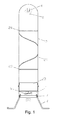
- the lighting plant ( Fig. 1 ) comprises a base 1 with supports 2, an inflatable shell 3 secured to the base, and an electric lamp 4 inside the shell, the lamp connected to a power supply (not shown), wherein the inner cavity 5 ( Fig. 1 ) of the inflatable shell is in communication with an air blower 6 installed in the base 1.
- the air blower is in communication with atmosphere via an opening (not shown) provided in the base.
- a fan can be employed, the fan connected to a rotation drive (not shown).
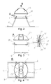
- Each support 2 has a joint 7 configured to turn the support over the base in a front plane and to fix it in the lower working position ( Figs. 1 to 4 ) and in the upper transportation position ( Figs. 5, 6 ).
- each support 2 is implemented as a hollow rod ( Figs. 2 to 6 ), a part 8 of which is bent and the rod has end portions.
- the joint 7 is located in each end portion.
- the bent parts 8 of the rods of the supports 2 are met ( Figs. 5, 6 ) and bound by a handle 9 for carrying the lighting plant.
- the bent parts 8 of the rods of the supports are positioned below the base 1 of the lighting plant ( Fig. 3 ).
- the handle 9 is made of a flexible and elastic material and owing to its elasticity the handle connects the bent parts 8 of the rods of the supports 2, when in the transportation position.
- each support 2 and the base 1 is implemented by a bracket 10 secured to the base ( Figs. 2 to 4 ), the bracket having ears 11 arranged at the ends thereof.
- Each ear has cheeks 12 placed opposite to each other (the magnified part in Fig. 3 ) and the end of the support 2 is arranged in each ear 11 between the cheeks 12, said end connected to the bracket 10 by means of the joint 7.
- the joint may be implemented as a round-section cylinder member such as a bolt, a pin or a shaft having means for fixing said member in the openings of the bracket.
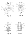
- the joint 7 e.g. a cylinder member is freely disposed in a slot 13 ( Fig. 13 ) provided in the support 2, wherein a bar 14 is arranged inside the inner cavity of each support, the bar having outer protrusions 15 engaging recesses 16 ( Fig. 14 ) provided at each end of the bracket 10.
- the bar 14 is connected to the joint 7 by means of a spring 17 placed inside the cavity of each of the supports 2.
- a few recesses are provided at each end of the bracket, the recesses corresponding to positions of the support.
- the protrusions 15 of the support 2 serve as clamps enabling the support to be fixed in a predetermined upper position and in lower positions.
- Each support 2 is bent in a front plane as shown in Fig. 1 .
- the supports 2 are bent in two planes, i.e. a lengthwise (front) plane and a transversal plane, as shown in Figs. 7 and 8 thus enabling the load bearing footprint of the lighting plant to be increased and improving its stability.
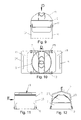
- each support 2 ( Figs. 9 to 12 ) is made molded of a plastic material or blanked of a sheet material.
- a substantial feature of such a support is that the support has a solid guard wall 18 configured to shield the inflatable shell from a side, when the shell is in folded transportation position.
- each support has a cutout 19 ( Figs. 10, 11 ) for a hand to carry the plant being in folded transportation position.
- the support 2 can also be fixed on the bracket 10 by means of clamps 20 which are spring-loaded by springs 21 ( Figs. 15, 16 ).
- the clamps 20 engage openings 22 provided in the bracket 10.
- the clamps 20 are movably installed in openings 23 of the support.
- the openings 22 are arranged as to be aligned with the openings 23 when the support is turned from its uppermost position to the lower working positions.
- each support 2 can also be fixed on the bracket 10 by means of a plurality of bosses 24 provided on the cheeks 12 of the ear 11 of the bracket 10, the bosses arranged circumferentially with the center of the circumference coincided with the shaft of the joint 7 (only two pairs of the bosses 24 are shown in Figs. 17 and 18 ).
- the pairs of the bosses are facing each other and the support 2 can be forced to pass between them when the support is turned from its uppermost position to the lower working positions and vice versa.
- the ear 11 is configured to allow its cheeks to be parted aside when the support 2 passes between the cheeks and the support interacts with the bosses 24. This is why the distance s between the bosses 24 is less than thickness t of the end portion of the support ( Fig. 18 ).
- the supports 2 are arranged in such a way that the supports are bent at least in one plane and serve inter alia as guard members which in one case ( Figs. 5, 6 ) may be portions of the rod of the support 2, and in another case ( Figs. 11, 12 ) the guard member of each support may be the solid wall 18, when the supports are made by molding or blanking, wherein when the lighting plant is in folded transportation position, its folded inflatable shell 3 with electric lamp 4 is positioned inside a protective jacket 25 which in turn is positioned between said guard members (i.e. portions of the rod of the support 2) or between the walls 18 of the supports as shown in Figs. 11, 12 .
- each support 2 is connected to the base by means of the bracket 10 which is rigidly fastened to the base 1, therefore it is provided that the brackets 10 can be installed on the power plant which feeds the lighting plant with electric current.
- each bracket 10 has means for connecting the lighting plant to the power plant e.g. to a current generator which is electrically connected to the lighting plant during operation, said means located on the bottom side of the bracket 10 ( Fig. 19 ).
- the means for connecting the lighting plant to the power plant are configured e.g. as sockets 26 ( Fig. 19 ) located between the joints 7 which link the supports to the base, wherein each socket 26 is configured to engage a load-bearing member 27 of the power plant 28 ( Fig. 20 ).
- the lighting plant can be equipped with means 29 for adjusting and changing its height.
- Said means 29 are configured as quick-operated releasable fasteners like zip fasteners.
- the plant operates as follows. During transporting the plant is in a position shown in Figs. 5, 6 or Figs. 11, 12 . This position protects the lighting plant (particularly its shell and electric lamp) from mechanical impact and damage, wherein the folded supports 2 are bound by a handle 9 ( Figs. 5, 6 ) or are met when the plant is in the transportation position ( Figs. 11, 12 ) in such a way that the cutouts 19 of the supports are positioned side by side and form a handle. Said handles provide convenient loading, unloading and carrying the lighting plant.
- the supports 2 are parted aside and set into the working position. If the handle 9 is used for bounding the supports 2, parts of the handle 9 are bent aside beforehand and the supports 2 are released from the handle 9.
- the supports are installed into the working position in the following way. With lighting plant placed on the ground, the plant is tilted to one side and one support 2 is turned around the joints 7, then the plant is tilted to the opposite side and the other support 2 is turned around the joints 7.
- the parted aside supports are installed on the ground as shown in Figs. 2 and 3 .
- Projection length of the supports 2 and slope angles thereof are selected and the supports are fixed on the bracket 10 by means of protrusions 15 engaging the recesses 16 corresponding to the slope angles of the supports ( Figs. 13, 14 ).
- Each support takes its working position ( Figs. 2, 3 ) and is held in said position due to tension of the spring 17 which pulls up the support 2 to the joint 7 through the bar 14.
- the supports are fixed on the bracket by means of clamps 20 which are brought into the openings 22 of the brackets 10 ( Figs. 15, 16 ).
- the supports are fixed on the bracket by means of the bosses 24 provided on the cheeks 12 of the ears of the bracket 10 ( Figs. 17, 18 ).
- the supports 2 are forced to turn around the joints 7 so as to pass them between the bosses 24 in one direction and prevent the supports from turning in reverse direction.
- the drive of the air blower 6 ( Fig. 1 ) is activated and air is charged into the cavity 5 of the shell by means of the blower.
- the shell 3 is inflated with air and the upper part of the shell along with the electric lamp 4 rises up and the shell takes its working position as shown in Fig. 1 .
- the electric lamp is switched on and surrounding territory is illuminated.
- the lighting plant is folded via backward sequence of actions.
- the parts of the rods used as the supports in one embodiment, or guard walls 18 in another embodiment of the supports are closed and the supports form a protective force loop around the shell and the electric lamp disposed therein, the loop reducing probability of damaging the shell and the electric lamp during loading, unloading and transporting the lighting plant.
- the supports 2 take the load of its weight, wherein the supports which are parted aside and end portions of the supports, which end portions are bent aside, increase the projection length of abutment points of the supports relative to the vertical axis of the plant, thus increasing stability of the plant.
- the projection length of the supports is adjusted by means of recesses 16 ( Fig. 13 ) in which the protrusions 15 of the supports 2 are set selectively ( Fig. 14 ), or by means of the openings 22 of the brackets 10 ( Fig. 15 ) in which the clamps 20 of the supports 2 are set selectively ( Fig. 16 ). Adjusting the projection length of the supports by changing the slope angle thereof is also provided by means of bosses 24 ( Figs.
- a plurality of bosses 24 can be provided on the cheeks 12 of the ear 11 of the bracket 10, the bosses enabling the supports to be fixed in a predetermined position with a predetermined slope angle thereof.
- Figs. 17 and 18 show only two pairs of the bosses 24.
- a method of using the lighting plant is provided, the method characterized by the following sequence of actions.
- the brackets 10 are fixed on the load-bearing members 27 of the power plant 28 by entering the members 27 into sockets 26 of the brackets ( Figs. 19, 20 ).
- the load-bearing members 27 are forced and locked in the sockets 26 of the brackets.
- the lighting plant is electrically connected to the power plant 28. Air is charged into the inflatable shell by means of the air blower 6 ( Fig. 1 ).
- the power plant 28 is placed on the ground between the supports 2 of the lighting plant.
- the slope angle of the supports 2 and the projection length thereof are adjusted in such a way that the weight load of the lighting plant is evenly distributed over the supports 2 and the power plant 28.
- the lighting plant is used being in secured position upon the power plant 28. Besides the specified advantageous effect, all the above improve stability of the lighting plant in use, which is a substantial factor when the lighting plant is used under extremely emergency conditions related to rescue operations.
- this method of using the lighting plant facilitates cooling the power plant and improves reliability of its operation as the air flow captured by the air blower 6 from the atmosphere passes through the area where the power plant 28 is located ( Fig. 20 ). This is specifically beneficial when the lighting plants and the power plants are used under hot climate conditions and under conditions of technogenic disasters in areas of thermal risks for machinery.
Landscapes
- Engineering & Computer Science (AREA)
- General Engineering & Computer Science (AREA)
- Life Sciences & Earth Sciences (AREA)
- Sustainable Development (AREA)
- Sustainable Energy (AREA)
- Non-Portable Lighting Devices Or Systems Thereof (AREA)
- Lighting Device Outwards From Vehicle And Optical Signal (AREA)
- Cultivation Of Plants (AREA)
Applications Claiming Priority (2)
| Application Number | Priority Date | Filing Date | Title |
|---|---|---|---|
| EA201001107A EA015704B1 (ru) | 2010-07-22 | 2010-07-22 | Осветительная установка |
| PCT/RU2011/000543 WO2012011849A1 (ru) | 2010-07-22 | 2011-07-21 | Осветительная установка и способ ее использования |
Publications (2)
| Publication Number | Publication Date |
|---|---|
| EP2597351A1 true EP2597351A1 (de) | 2013-05-29 |
| EP2597351A4 EP2597351A4 (de) | 2015-05-20 |
Family
ID=43778134
Family Applications (1)
| Application Number | Title | Priority Date | Filing Date |
|---|---|---|---|
| EP20110809942 Withdrawn EP2597351A4 (de) | 2010-07-22 | 2011-07-21 | Beleuchtungseinheit und verfahren zur herstellung davon |
Country Status (7)
| Country | Link |
|---|---|
| US (1) | US8931916B2 (de) |
| EP (1) | EP2597351A4 (de) |
| CN (1) | CN203082584U (de) |
| AU (1) | AU2011280306A1 (de) |
| EA (1) | EA015704B1 (de) |
| UA (1) | UA106436C2 (de) |
| WO (1) | WO2012011849A1 (de) |
Families Citing this family (9)
| Publication number | Priority date | Publication date | Assignee | Title |
|---|---|---|---|---|
| GB2492376A (en) * | 2011-06-29 | 2013-01-02 | Megaflatables Ltd | Inflatable advertising assembly, e.g. air guy. |
| CN102900918A (zh) * | 2012-07-11 | 2013-01-30 | 北京科力康技贸有限公司 | 能保障充气结构支撑的功能装置倾倒时避免损坏的方法 |
| CN103968262A (zh) * | 2014-04-02 | 2014-08-06 | 刘嘉雯 | 一种分体式太阳能充气灯 |
| CN106965134B (zh) * | 2017-05-16 | 2023-08-18 | 四川钰萌光电科技有限公司 | 用于装配路灯灯杆法兰底盘与基座的工作平台及装配方法 |
| US11287103B2 (en) | 2019-04-22 | 2022-03-29 | Ism Lighting, Llc. | Low wattage balloon work light |
| RU207358U1 (ru) * | 2020-11-17 | 2021-10-25 | Александр Григорьевич Булатов | Аварийная осветительная установка |
| US11181248B1 (en) * | 2021-03-19 | 2021-11-23 | Manish Kothari | Temporary and/or emergency lighting system with inflatable structure using an LED array |
| CN114261466B (zh) * | 2022-01-13 | 2023-01-31 | 浙江大学 | 一种可便携移动的照明装置及具有该照明装置的平衡车 |
| WO2025250050A1 (ru) * | 2024-05-28 | 2025-12-04 | Илья Борисович НАЛИЧАЕВ | Осветительная установка и надувная оболочка для осветительной установки (варианты) |
Family Cites Families (16)
| Publication number | Priority date | Publication date | Assignee | Title |
|---|---|---|---|---|
| FR2314970A1 (fr) * | 1975-06-19 | 1977-01-14 | Tardieux Jean Pierre | Dispositif de signalisation d'urgence a structure gonflable |
| DE9404275U1 (de) * | 1994-03-14 | 1994-05-19 | Pop Points Of Publicity Marketing Ges. M.B.H., Marchtrenk | Werbeständer, wie Litfaßsäule, Reklamevitrine etc. |
| ITVE980007U1 (it) | 1998-03-16 | 1999-09-16 | Medici Guido | Kit di illuminazione di emergenza con struttura gonfiata con aria sof fiante |
| ITMS20010002A1 (it) | 2001-02-07 | 2002-08-07 | Marco Tambini | Sistema di illuminazione di emergenza gonfiabile |
| RU2192581C1 (ru) | 2001-02-26 | 2002-11-10 | Налогин Дмитрий Олегович | Аварийная осветительная установка |
| US6892772B1 (en) * | 2004-02-04 | 2005-05-17 | Hua-Chiang Wang | Rotating inflatable device with built-in blower and sensor light |
| RU2286510C9 (ru) * | 2004-11-03 | 2007-06-10 | Борис Владимирович Наличаев | Световая башня, опора световой башни (варианты), способ управления работой световой башни и блок управления работой световой башни для реализации способа |
| AU2006294474A1 (en) * | 2005-09-28 | 2007-04-05 | The Coleman Company, Inc. | Tent electrical system |
| US7320529B2 (en) * | 2005-10-26 | 2008-01-22 | Siong Kiat Goh | Illuminating balloon |
| RU57870U1 (ru) * | 2006-05-30 | 2006-10-27 | Александр Григорьевич Булатов | Аварийная осветительная установка |
| RU59774U1 (ru) * | 2006-08-21 | 2006-12-27 | Александр Григорьевич Булатов | Установка осветительная "шар световой" |
| CN201093391Y (zh) * | 2007-09-12 | 2008-07-30 | 和建东企业有限公司 | 吹气发光棒结构 |
| JP2009081011A (ja) * | 2007-09-26 | 2009-04-16 | Light Boy Co Ltd | 投光機 |
| RU74441U1 (ru) * | 2008-02-04 | 2008-06-27 | Александр Григорьевич Булатов | Установка осветительная "шар световой - зонтик" |
| US8328377B1 (en) * | 2010-08-20 | 2012-12-11 | Manish Kothari | Temporary and/or emergency lighting system with inflatable bearing structure |
| US8939593B2 (en) * | 2010-08-20 | 2015-01-27 | Manish Kothari | Temporary and/or emergency lighting system with inflatable bearing structure |
-
2010
- 2010-07-22 EA EA201001107A patent/EA015704B1/ru not_active IP Right Cessation
-
2011
- 2011-07-21 AU AU2011280306A patent/AU2011280306A1/en not_active Abandoned
- 2011-07-21 CN CN2011900003635U patent/CN203082584U/zh not_active Expired - Fee Related
- 2011-07-21 EP EP20110809942 patent/EP2597351A4/de not_active Withdrawn
- 2011-07-21 WO PCT/RU2011/000543 patent/WO2012011849A1/ru not_active Ceased
- 2011-07-21 US US13/806,273 patent/US8931916B2/en not_active Expired - Fee Related
- 2011-07-21 UA UAA201302146A patent/UA106436C2/ru unknown
Also Published As
| Publication number | Publication date |
|---|---|
| US8931916B2 (en) | 2015-01-13 |
| AU2011280306A1 (en) | 2013-02-28 |
| EA201001107A1 (ru) | 2011-02-28 |
| US20130229792A1 (en) | 2013-09-05 |
| UA106436C2 (ru) | 2014-08-26 |
| EP2597351A4 (de) | 2015-05-20 |
| WO2012011849A1 (ru) | 2012-01-26 |
| CN203082584U (zh) | 2013-07-24 |
| EA015704B1 (ru) | 2011-10-31 |
Similar Documents
| Publication | Publication Date | Title |
|---|---|---|
| US8931916B2 (en) | Lighting installation and method for using the same | |
| US7824079B2 (en) | Light tower diffuser | |
| US10704288B2 (en) | Temporary maintenance enclosures and methods of maintaining turbine blades | |
| CN1104584C (zh) | 具有可膨胀支承构架的临时和/或紧急照明系统 | |
| ES2382705T3 (es) | Un procedimiento para el manejo y/o mantenimiento de componentes de una turbina eólica y un aparato de sujeción para realizar el procedimiento | |
| US7621650B2 (en) | Light tower, light tower support, method for operating a light tower and a light tower control unit for carrying out said method | |
| US8272822B2 (en) | Wind power turbine blade packing and packing method | |
| CN105673351A (zh) | 用于风力涡轮机塔架的箍条 | |
| WO2005068901A1 (ja) | 投光機 | |
| EP2665651A1 (de) | System zur bereitstellung einer schnell erhöhten aerostat-plattform | |
| US9063702B2 (en) | Air supported frame for an LED display | |
| AU2015203161B2 (en) | Lighting Plant And Method Of Using The Same | |
| KR20170000647U (ko) | 격납고용 접철식 플랫폼 | |
| US20170007858A1 (en) | Fall Arrest System | |
| JP2015198492A (ja) | 気中ケーブルヘッド用の作業足場 | |
| KR101615481B1 (ko) | 원자력 발전소의 대차 유닛 | |
| KR100888012B1 (ko) | 조명장치 | |
| JP3119576B2 (ja) | 落下物受止めネット | |
| GB2492376A (en) | Inflatable advertising assembly, e.g. air guy. | |
| KR101732696B1 (ko) | 건축물 소방 재난 구조용 완강기 지지대 | |
| ES2807954T3 (es) | Plataforma de mantenimiento, así como dispositivo para el mantenimiento de componentes internos en una torre de un aerogenerador y procedimiento para el montaje de una plataforma de mantenimiento | |
| CN112591266B (zh) | 一种螺旋桨运输装置 | |
| GB2151285A (en) | Portable safety hazard barrier | |
| ES2427849B1 (es) | Protector superficial recuperable de las ruedas de vehículos en las operaciones de pintado de las carrocerías | |
| CN211780208U (zh) | 乙炔钢瓶移动固定架 |
Legal Events
| Date | Code | Title | Description |
|---|---|---|---|
| PUAI | Public reference made under article 153(3) epc to a published international application that has entered the european phase |
Free format text: ORIGINAL CODE: 0009012 |
|
| 17P | Request for examination filed |
Effective date: 20130222 |
|
| AK | Designated contracting states |
Kind code of ref document: A1 Designated state(s): AL AT BE BG CH CY CZ DE DK EE ES FI FR GB GR HR HU IE IS IT LI LT LU LV MC MK MT NL NO PL PT RO RS SE SI SK SM TR |
|
| DAX | Request for extension of the european patent (deleted) | ||
| RA4 | Supplementary search report drawn up and despatched (corrected) |
Effective date: 20150420 |
|
| RIC1 | Information provided on ipc code assigned before grant |
Ipc: F21V 21/06 20060101ALI20150414BHEP Ipc: F21L 13/00 20060101ALI20150414BHEP Ipc: F21V 17/00 20060101ALI20150414BHEP Ipc: F21W 131/10 20060101ALI20150414BHEP Ipc: F21V 3/02 20060101AFI20150414BHEP Ipc: F21W 131/40 20060101ALI20150414BHEP |
|
| 17Q | First examination report despatched |
Effective date: 20160226 |
|
| STAA | Information on the status of an ep patent application or granted ep patent |
Free format text: STATUS: THE APPLICATION IS DEEMED TO BE WITHDRAWN |
|
| 18D | Application deemed to be withdrawn |
Effective date: 20160708 |