EP2597355A1 - Glühlampenförmige leuchte und beleuchtungsvorrichtung - Google Patents
Glühlampenförmige leuchte und beleuchtungsvorrichtung Download PDFInfo
- Publication number
- EP2597355A1 EP2597355A1 EP11829139.2A EP11829139A EP2597355A1 EP 2597355 A1 EP2597355 A1 EP 2597355A1 EP 11829139 A EP11829139 A EP 11829139A EP 2597355 A1 EP2597355 A1 EP 2597355A1
- Authority
- EP
- European Patent Office
- Prior art keywords
- case
- end side
- housing
- lighting circuit
- bulb
- Prior art date
- Legal status (The legal status is an assumption and is not a legal conclusion. Google has not performed a legal analysis and makes no representation as to the accuracy of the status listed.)
- Withdrawn
Links
Images



Classifications
-
- F—MECHANICAL ENGINEERING; LIGHTING; HEATING; WEAPONS; BLASTING
- F21—LIGHTING
- F21K—NON-ELECTRIC LIGHT SOURCES USING LUMINESCENCE; LIGHT SOURCES USING ELECTROCHEMILUMINESCENCE; LIGHT SOURCES USING CHARGES OF COMBUSTIBLE MATERIAL; LIGHT SOURCES USING SEMICONDUCTOR DEVICES AS LIGHT-GENERATING ELEMENTS; LIGHT SOURCES NOT OTHERWISE PROVIDED FOR
- F21K9/00—Light sources using semiconductor devices as light-generating elements, e.g. using light-emitting diodes [LED] or lasers
- F21K9/20—Light sources comprising attachment means
- F21K9/23—Retrofit light sources for lighting devices with a single fitting for each light source, e.g. for substitution of incandescent lamps with bayonet or threaded fittings
- F21K9/232—Retrofit light sources for lighting devices with a single fitting for each light source, e.g. for substitution of incandescent lamps with bayonet or threaded fittings specially adapted for generating an essentially omnidirectional light distribution, e.g. with a glass bulb
-
- F—MECHANICAL ENGINEERING; LIGHTING; HEATING; WEAPONS; BLASTING
- F21—LIGHTING
- F21V—FUNCTIONAL FEATURES OR DETAILS OF LIGHTING DEVICES OR SYSTEMS THEREOF; STRUCTURAL COMBINATIONS OF LIGHTING DEVICES WITH OTHER ARTICLES, NOT OTHERWISE PROVIDED FOR
- F21V17/00—Fastening of component parts of lighting devices, e.g. shades, globes, refractors, reflectors, filters, screens, grids or protective cages
- F21V17/10—Fastening of component parts of lighting devices, e.g. shades, globes, refractors, reflectors, filters, screens, grids or protective cages characterised by specific fastening means or way of fastening
- F21V17/16—Fastening of component parts of lighting devices, e.g. shades, globes, refractors, reflectors, filters, screens, grids or protective cages characterised by specific fastening means or way of fastening by deformation of parts; Snap action mounting
- F21V17/164—Fastening of component parts of lighting devices, e.g. shades, globes, refractors, reflectors, filters, screens, grids or protective cages characterised by specific fastening means or way of fastening by deformation of parts; Snap action mounting the parts being subjected to bending, e.g. snap joints
-
- F—MECHANICAL ENGINEERING; LIGHTING; HEATING; WEAPONS; BLASTING
- F21—LIGHTING
- F21V—FUNCTIONAL FEATURES OR DETAILS OF LIGHTING DEVICES OR SYSTEMS THEREOF; STRUCTURAL COMBINATIONS OF LIGHTING DEVICES WITH OTHER ARTICLES, NOT OTHERWISE PROVIDED FOR
- F21V29/00—Protecting lighting devices from thermal damage; Cooling or heating arrangements specially adapted for lighting devices or systems
- F21V29/50—Cooling arrangements
- F21V29/502—Cooling arrangements characterised by the adaptation for cooling of specific components
- F21V29/507—Cooling arrangements characterised by the adaptation for cooling of specific components of means for protecting lighting devices from damage, e.g. housings
-
- F—MECHANICAL ENGINEERING; LIGHTING; HEATING; WEAPONS; BLASTING
- F21—LIGHTING
- F21V—FUNCTIONAL FEATURES OR DETAILS OF LIGHTING DEVICES OR SYSTEMS THEREOF; STRUCTURAL COMBINATIONS OF LIGHTING DEVICES WITH OTHER ARTICLES, NOT OTHERWISE PROVIDED FOR
- F21V29/00—Protecting lighting devices from thermal damage; Cooling or heating arrangements specially adapted for lighting devices or systems
- F21V29/50—Cooling arrangements
- F21V29/70—Cooling arrangements characterised by passive heat-dissipating elements, e.g. heat-sinks
-
- F—MECHANICAL ENGINEERING; LIGHTING; HEATING; WEAPONS; BLASTING
- F21—LIGHTING
- F21V—FUNCTIONAL FEATURES OR DETAILS OF LIGHTING DEVICES OR SYSTEMS THEREOF; STRUCTURAL COMBINATIONS OF LIGHTING DEVICES WITH OTHER ARTICLES, NOT OTHERWISE PROVIDED FOR
- F21V3/00—Globes; Bowls; Cover glasses
- F21V3/02—Globes; Bowls; Cover glasses characterised by the shape
-
- F—MECHANICAL ENGINEERING; LIGHTING; HEATING; WEAPONS; BLASTING
- F21—LIGHTING
- F21K—NON-ELECTRIC LIGHT SOURCES USING LUMINESCENCE; LIGHT SOURCES USING ELECTROCHEMILUMINESCENCE; LIGHT SOURCES USING CHARGES OF COMBUSTIBLE MATERIAL; LIGHT SOURCES USING SEMICONDUCTOR DEVICES AS LIGHT-GENERATING ELEMENTS; LIGHT SOURCES NOT OTHERWISE PROVIDED FOR
- F21K9/00—Light sources using semiconductor devices as light-generating elements, e.g. using light-emitting diodes [LED] or lasers
- F21K9/20—Light sources comprising attachment means
- F21K9/23—Retrofit light sources for lighting devices with a single fitting for each light source, e.g. for substitution of incandescent lamps with bayonet or threaded fittings
- F21K9/238—Arrangement or mounting of circuit elements integrated in the light source
-
- F—MECHANICAL ENGINEERING; LIGHTING; HEATING; WEAPONS; BLASTING
- F21—LIGHTING
- F21V—FUNCTIONAL FEATURES OR DETAILS OF LIGHTING DEVICES OR SYSTEMS THEREOF; STRUCTURAL COMBINATIONS OF LIGHTING DEVICES WITH OTHER ARTICLES, NOT OTHERWISE PROVIDED FOR
- F21V23/00—Arrangement of electric circuit elements in or on lighting devices
- F21V23/003—Arrangement of electric circuit elements in or on lighting devices the elements being electronics drivers or controllers for operating the light source, e.g. for a LED array
- F21V23/004—Arrangement of electric circuit elements in or on lighting devices the elements being electronics drivers or controllers for operating the light source, e.g. for a LED array arranged on a substrate, e.g. a printed circuit board
- F21V23/006—Arrangement of electric circuit elements in or on lighting devices the elements being electronics drivers or controllers for operating the light source, e.g. for a LED array arranged on a substrate, e.g. a printed circuit board the substrate being distinct from the light source holder
-
- F—MECHANICAL ENGINEERING; LIGHTING; HEATING; WEAPONS; BLASTING
- F21—LIGHTING
- F21Y—INDEXING SCHEME ASSOCIATED WITH SUBCLASSES F21K, F21L, F21S and F21V, RELATING TO THE FORM OR THE KIND OF THE LIGHT SOURCES OR OF THE COLOUR OF THE LIGHT EMITTED
- F21Y2115/00—Light-generating elements of semiconductor light sources
- F21Y2115/10—Light-emitting diodes [LED]
Definitions
- Embodiments of the present invention relate to a bulb-shaped lamp in which a semiconductor light emitting element is used, and a lighting device in which the bulb-shaped lamp is used.
- the bulb-shaped lamp in a bulb-shaped lamp using a semiconductor light emitting element, a metal housing is included, a light emitting module having the semiconductor light emitting element on one end side of the housing is arranged, and a globe which covers the light emitting module is attached to one end of the housing.
- the bulb-shaped lamp includes a case formed of a synthetic resin which is arranged in the housing, accommodates a lighting circuit in the case, and has a base which is attached to the other end of the case.
- the housing As the housing, a housing which is formed by aluminum die-casting which has an excellent heat radiation has been widely used, however, it may be a housing which is formed by press molding.
- the lighting circuit includes a lighting circuit board which is vertically arranged along the axis direction of the lamp in the case, however, since the width of the lighting circuit board is limited to be small, the length of the lighting circuit board in the lamp axis direction is set to be large so as to secure a mounting area which is necessary for mounting components of the lighting circuit.
- the bulb-shaped lamp of which the housing is formed using the press molding mounts the light emitting module on one end side surface of a metal heat radiating plate, and causes the heat radiating plate to come into contact with the housing, thereby radiating heat which is generated when lighting up the semiconductor light emitting element from the housing to the outside, by causing the heat to be thermally conducted to the housing from the heat radiating plate.
- the length of the lighting circuit board in the lamp axis direction is set to be large so as to secure a mounting area which is necessary for mounting the components of the lighting circuit.
- an insulating member is interposed between the lighting circuit board and the heat radiating plate.
- a lighting circuit board in the lamp axis direction is large, a lighting circuit board and a heat radiating plate are close to each other, and as a result, it is not possible to establish an insulating distance which is necessary between the lighting circuit board and the heat radiating plate, and it is necessary to interpose an insulating member between the lighting circuit board and the heat radiating plate, there is a problem in that a structure becomes complicated, or the number of components increases.
- the bulb-shaped lamp of which a housing is formed by press molding has a large space compared to a housing which is formed by aluminum die-casting, however, the space has not been effectively used even though it is possible to make a space in the housing large.
- the present invention was made in consideration of such a problem, and an object of the present invention is to provide a bulb-shaped lamp in which a necessary insulating distance is established without interposing an insulating member between a lighting circuit board and a heat radiating plate, and a lighting device in which the bulb-shaped lamp is used.
- the bulb-shaped lamp according to the embodiment includes a metal housing which is formed in a cylindrical shape which is widely open toward one end side using press molding.
- a synthetic resin case which is formed in a cylindrical shape which is widely open toward one end side is arranged in the housing along the inner surface of the housing.
- a base is attached to the other end side of the case.
- a heat radiating plate on which a light emitting module including a semiconductor light emitting element is mounted is arranged on one end side of the housing.
- a lighting circuit is accommodated in the case.
- the lighting circuit has a lighting circuit board which is vertically arranged in the case in the lamp axis direction.
- the lighting circuit board is formed in a shape in which one end side thereof becomes wide in width along the inner shape of the case, and is arranged at a position which is close to the base in the case.
- 11 denotes a bulb-shaped lamp
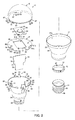
- the bulb-shaped lamp 11 includes: a cylindrical housing 12; a case 13 which is arranged in the housing 12 by being inserted from one end side (one end side in a lamp axis direction in which a globe 18 of the bulb-shaped lamp 11 and base 15 are connected), and the other end is protruded from the housing 12; a ring 14 which fixes the other end of the case 13 to the housing 12, the base 15 which is attached to the other end of the case 13; a light emitting module 16 which is arranged on one end side of the housing 12 and case 13; a heat radiating plate 17 which is attached to one end side of the case 13 by mounting the light emitting module 16 on one end side surface, the globe 18 which is fitted into one end side of the housing 12, and is attached to one end side of the case 13; and a lighting circuit 19 which is arranged in the case 13.
- the bulb-shaped lamp 11 is formed in a shape almost close to an incandescent light bulb as a whole by having the same length in the lamp axis direction, and the same outer diameter at a portion with a maximum diameter in the direction intersecting the lamp axis direction as those in an incandescent light bulb for general illumination.
- the housing 12 is formed of metal with excellent heat conductivity and heat radiation, and is formed in a cylindrical shape in which its diameter increases toward one end side from the other end side by press molding.
- a cylindrical tapered portion 22 which expands in diameter toward one end side from the other end side is formed, a cylinder portion 23 which is parallel to the lamp axis is formed at one end of the tapered portion 22, and an engagement unit 24 which is bent toward the center side of the lamp axis is formed at the other end thereof.
- a tapered surface 22a which widely opens to one end side is formed on the inner surface of the tapered portion 22.
- a plurality of notch portions (not shown) which are used for positioning the case 13 are formed in the engagement unit 24.
- both ends of the case 13 in the lamp axis direction are open using, for example, a synthetic resin having insulating property such as PBT resin, and the case is formed in a cylindrical shape which widely opens toward one end side.
- a case main body 27 which is arranged along the inner side of the housing 12, a base attaching portion 28 which protrudes from the other end side of the housing 12, and a step portion 29 which is engaged with the engagement unit 24 of the housing 12 between the case main body 27 and the base attaching portion 28 are formed.
- the case main body 27 is formed in a tapered shape which widely opens toward one end side in the lamp axis direction, and becomes a similar shape to the inner surface shape of the housing 12 so as to be arranged along the tapered surface 22a on the inner surface of the tapered portion 22 of the housing 12. That is, the inner surface of the case main body 27 is formed as a tapered surface which widely opens toward the one end side.
- a plurality of bosses 31 having a mounting hole 30 for screwing up a heat radiating plate 17 are formed on the inner surface on one end side of the case main body 27 along the lamp axis direction.
- the bosses 31 are formed at two portions which are symmetric to the center of the case main body 27, however, the bosses may be formed at three portions without being limited to two.
- a plurality of globe attaching units 32 for attaching the globe 18 are formed at one end of the case main body 27.
- the globe attaching units 32 are formed at three portions at regular intervals in the circumferential direction at one end of the case main body 27, however, the globe attaching units may be formed at two portions, or four portions or more without being limited to three portions.
- Each of the globe attaching units 32 has a positioning protrusion 33 which protrudes from the case main body 27 in one end direction, and a locking claw 34, respectively.
- the positioning protrusion 33 is formed in a tapered shape in which the width on the tip end side becomes narrow, and has a larger protruding dimension to one end direction than that of the locking claw 34.
- the locking claw 34 is formed with a claw 35 which protrudes toward the outer diameter direction at the tip end thereof.
- a wiring guide 36 is formed at one portion of one end of the case main body 27.
- a pair of board holding units 37 for holding a lighting circuit board 74 of a lighting circuit 19 faces to each other, and is formed along the lamp axis direction across the inner surface of the base attaching portion 28 from the inner surface of the case main body 27 of the case 13.
- the pair of board holding units 37 is formed at a position which is offset from the center of the case 13 as one side position of each of bosses 31 which is formed at two portions which are symmetric to the center of the case main body 27.
- a holding groove 38 to which the lighting circuit board 74 of the lighting circuit 19 is inserted is formed along the lamp axis direction.
- a locking unit 39 which locks the lighting circuit board 74 of the lighting circuit 19 which is inserted into the board holding units 37 is formed on one end side of each of the board holding units 37.
- the locking unit 39 is configured by a hook of which one end side is connected to the case 13, and of which the other end side is a free end.
- a plurality of protrusions (not shown) which are fitted into each notch portion of the engagement unit 24 of the housing 12, and position a position in the circumferential direction are formed on the step portion 29.
- the ring 14 is formed of a synthetic resin having an insulating property such as PBT resin, for example, insulates the housing 12 and the base 15 therebetween by being interposed therebetween, and interposes the engagement unit 24 of the housing 12 between the ring and the step portion 29 of the case 13.
- a plurality of concave portions 42 which position a position in the circumferential direction by being fitted into each protrusion of the case 13 are formed in the ring 14.
- the base 15 can be connected to a socket for an E26 light bulb for general illumination, and includes a shell 45 which is fixed by being screwed to the circumferential surface of the base attaching portion 28 of the case 13, an insulating unit 46 which is provided on the other end side of the shell 45, and an eyelet 47 which is provided at an apex of the insulating unit 46.
- a light emitting module 16 includes a rectangular plate-shaped board (module board) 50 which is formed of, for example, metal such as aluminum having excellent heat conductivity, or ceramics, a surface light source 51 as a light source which is formed in the center area of one surface as one end side surface of the board 50, and a connector 52 which is mounted in the periphery of one surface of the board 50.
- module board which is formed of, for example, metal such as aluminum having excellent heat conductivity, or ceramics
- a surface light source 51 as a light source which is formed in the center area of one surface as one end side surface of the board 50
- a connector 52 which is mounted in the periphery of one surface of the board 50.
- a semiconductor light emitting element 51a such as an LED element, or an EL element, for example, having a surface-shaped light emitting surface of ⁇ 2 mm or more is used.
- the LED element is used as the semiconductor light emitting element 51a, and a COB (Chip On Board) method in which the plurality of LED elements are mounted on the board 50 is adopted. That is, the plurality of LED elements are mounted on the board 50, these plurality of LED elements are electrically connected in series using wiring bonding, and the plurality of LED elements are integrally covered by a phosphor layer which is formed of a transparent resin such as a silicon resin, for example, in which phosphor is mixed.
- the LED element for example, an LED element which emits a blue light is used, and phosphor which radiates a yellow light which is excited by a part of the blue light from the LED element is mixed into the phosphor layer.
- the surface light source 51 is configured by the LED element, the phosphor layer, or the like, the surface of the phosphor layer as the surface of the surface light source 51 becomes the light emitting surface, and illumination light of a white system is radiated from the light emitting surface.
- a wiring pattern which is not shown is formed on one surface of the board 50, and the plurality of LED elements, and the connector 52 are connected to the wiring pattern.
- a plurality of through holes 53 for being screwed to the heat radiating plate 17 are formed in the periphery of the board 50.
- the heat radiating plate 17 is formed in a flat disk shape using metal, for example, aluminum or the like, which has excellent heat conductivity, or ceramics.
- a concave portion 56 into which the other surface side of the board 50 of the light emitting module 16 is fitted is formed on one surface of the heat radiating plate 17, and a plurality of mounting holes 57 which screw up the board 50 through each through hole 53 of the board 50 are formed in the concave portion 56.
- a tapered surface 59 which is inclined at the same angle as the tapered surface 22a in the inner surface of the tapered portion 22 of the housing 12, and makes a surface contact with the tapered surface 22a from the inside of the housing 12 is formed on the thick end surface of plate 58 in the periphery of the heat radiating plate 17.
- a plurality of through holes 60 through which screws which are screwed into each boss 31 are inserted are formed corresponding to positions of each of bosses 31 of the case 13 in the vicinity of the periphery of the heat radiating plate 17.
- a plurality of notch portions 61 through which each globe attaching unit 32 of the case 13 passes on one end side are formed in the periphery of the heat radiating plate 17.
- Each of the notch portions 61 includes a notch portion 61a through which the positioning protrusion 33 passes, and a notch portion 61b through which the locking claw 34 passes.
- a notch portion 62 for wiring is formed in the periphery of the heat radiating plate 17 corresponding to a position of the wiring guide 36 of the case 13.
- the bulb-shaped lamp 11 In an assembled state of the bulb-shaped lamp 11, it is configured so that a gap 63 is formed between the other surface of the heat radiating plate 17 and one end of the case main body 27 of the case 13, the housing 12, the case 13, the ring 14, and the base 15 are integrally assembled, and further, in an assembled state in which the heat radiating plate 17 is fitted from one end side of the housing 12, and the tapered surface 59 of the heat radiating plate 17 is caused to make a surface contact with the tapered surface 22a of the housing 12, the gap 63 is formed between the other surface of the heat radiating plate 17 and one end of the case main body 27 of the case 13.
- the globe 18 is formed in a dome shape which is open to the other end side in the lamp axis direction, using a material such as a synthetic resin having transmittance and a light diffusion property, or glass, for example.
- a cylindrical fitting portion 66 which is fitted in parallel into the inner side of the cylinder portion 23 of the housing 12 is formed in a protruding manner at an opening edge portion of the other end side of the globe 18.
- the fitting portion 66 is formed in a cylindrical shape which is continuous in the circumferential direction without breaking or the like.
- a plurality of case attaching portions 67 which are attached to each globe attaching unit 32 of the case 13 are formed at the other end of the fitting portion 66.
- a wall portion 68 which protrudes to the other end side from the fitting portion 66 is formed in each case attaching portion 67, the groove portion 69 to which the positioning protrusion 33 is fitted is formed on the wall portion 68, and a locking hole 70 at which the claw 35 of the locking claw 34 is hooked by being fitted from the inner surface side of the wall portion 68 is formed.
- Both side surfaces in the groove portion 69 are inclined so as to widely open to the other end side in order to be fitted to both the side surfaces of the tapered positioning protrusion 33.
- a guiding groove 71 which guides the claw 35 of the locking claw 34 to the locking hole 70 is formed at the tip end of the wall portion 68.
- positions thereof in the lamp axis direction are regulated when the inner surface of the groove portion 69 comes into contact with the surface of the tip end of the positioning protrusion 33, and a positional relationship in which the claw 35 of the locking claw 34 is fitted to the locking hole 70 is formed in an attaching state of the globe 18 in which both side surfaces in the groove portion 69 comes into contact with both side surfaces of the positioning protrusion 33, and are regulated in position in the circumferential direction.
- the tip end of the wall portion 68 is alienated from one surface of the heat radiating plate 17 without being in contact.
- the lighting circuit 19 is a circuit which supplies a constant current to the LED element of the light emitting module 16, and includes the lighting circuit board 74 and a plurality of components of the lighting circuit (not shown) which are mounted on the lighting circuit board 74.
- the lighting circuit board 74 has one surface as a mounting surface on which main components of the lighting circuit are mounted, and another surface as a wiring pattern surface on which a wiring pattern is formed to which the lighting circuit components are electrically connected.
- the lighting circuit board 74 is inserted from one end side of the case 13, and is held when both sides of the lighting circuit board 74 are fitted into the holding groove 38 of the board holding unit 37. Accordingly, the lighting circuit board 74 is vertically arranged along the lamp axis direction in the case 13, and is arranged at an offset position from the center of the case 13 so that the distance between the mounting surface and the inner surface of the case 13 becomes wider than the distance between the wiring pattern surface and the inner surface of the case 13.
- the lighting circuit board 74 has a shape in which the width on one end side becomes wide along the inner surface shape of the case 13. That is, a narrow width portion 75 which is arranged in the base attaching portion 28 of the case 13 is formed on the other end side of the lighting circuit board 74, and a wide width portion 76 which is arranged in the case main body 27 of the case 13, has a wider width than the other end side, and becomes wide in width toward one end side is formed on one end side of the lighting circuit board 74.
- a regulation unit 77 which positions an insertion position into the case 13 by being in contact with the case 13 is formed between the narrow width portion 75 and the wide width portion 76.
- the lighting circuit board 74 since it is possible to make the mounting area of the lighting circuit board 74 wide by forming the one end side of the lighting circuit board 74 to be wide in width, it is possible to make the length of the lighting circuit board 74 in the lamp axis direction small while securing a mounting area which is necessary for mounting the components of the lighting circuit. In this manner, the lighting circuit board 74 is arranged at a position which is close to the base 15 side in the case 13, and it is possible to secure a necessary insulating distance L without interposing an insulating member between the lighting circuit board 74, the components of the lighting circuit and the heat radiating plate 17.
- the plurality of components of the lighting circuit as discrete components having lead wires are mounted on the mounting surface of the lighting circuit board 74.
- the lead wire of these components of the lighting circuit penetrates the lighting circuit board 74, and is connected to the wiring pattern on the wiring pattern surface using soldering.
- an electrolytic capacitor of a rectification smoothing circuit which rectifies and smoothes an AC voltage
- an inductor of a chopper circuit which converts a rectified and smoothed voltage to a predetermined voltage
- a large component such as a resistor which is used in the circuit, or small components such as a switching element, a capacitor, a diode, and the like of the chopper circuit are also included in addition to those.
- the larger components are arranged at one end side of which the inside diameter of the case 13 becomes large, and the smaller components are arranged at the other end side of which the inside diameter of the case 13 becomes small.
- surface mounted components are subject to surface mount on the wiring pattern surface of the lighting circuit board 74.
- a chip resistor, a chip capacitor, and the like are included.
- an input lead wire (not shown) is electrically connected to the shell 45 and the eyelet 47 of the base 15, respectively, through the other end opening of the case 13.
- an output lead wire having a connector which is not shown connected to the connector 52 of the light emitting module 16 is connected to the output side of the lighting circuit 19.
- the lighting circuit 19 is inserted into the case 13 from one end side of the case 13.
- both sides of the lighting circuit board 74 are inserted into the holding groove 38 of the board holding units 37 of the case 13
- both sides of the lighting circuit board 74 come into contact with the locking units 39 on both sides, and these locking units 39 are elastically deformed outward
- the lighting circuit board 74 goes on to the locking unit 39
- the locking unit 39 is hooked at one end side of the lighting circuit board 74
- the lighting circuit 19 is locked and held in the case 13.
- the output lead wire of the lighting circuit 19 is drawn outside the case 13 through a wiring guide 36 of the case 13.
- the case 13 is inserted from one end side of the housing 12, the base attaching portion 28 of the case 13 is protruded from the other end of the housing 12, the ring 14 is fitted into the outer periphery of the base attaching portion 28 of the case 13, and the base 15 is attached by being screwed.
- the input lead wire on one side of the lighting circuit 19 is connected to the eyelet 47 of the base 15, and the other lead wire is connected to the shell 45 of the base 15 which is arranged in the outer periphery of the base attaching portion 28 of the case 13, and is attached to the base attaching portion 28 by being screwed.
- the plurality of protrusions which are provided at the step portion 29 of the case 13 and the plurality of notch portions which are provided at the engagement unit 24 of the housing 12 are fitted to each other, and the case 13 and the housing 12 are prevented from being rotated.
- the heat radiating plate 17 is fitted to one end side of the housing 12 while causing the positioning protrusion 33 and the locking claw 34 which are protruded from one end of the case 13 to pass through each of the notch portions 61a and 61b in the periphery of the heat radiating plate 17.
- the tapered surface 59 of the thick end surface of plate 58 of the heat radiating plate 17 makes a surface contact with the tapered surface 22a in the inner surface of the tapered portion 22 from inside the housing 12.
- a screw is screwed to the mounting hole 30 of the boss 31 of the case 13 from the through hole 60 of the heat radiating plate 17, and the heat radiating plate 17 is fixed to the case 13 by being tightened using the screw.
- a tightening force using the screw is added to the bonding surface of the tapered surface 59 of the thick end surface of plate 58 of the heat radiating plate 17, and the tapered surface 22a of the tapered portion 22 of the housing 12, and the tapered surface 59 of the thick end surface of plate 58 of the heat radiating plate 17 comes into press contact with the tapered surface 22a of the tapered portion 22 of the housing 12, thereby securing good heat conductivity.
- a silicon resin may be interposed between the tapered surface 59 of the thick end surface of plate 58 of the heat radiating plate 17 and the tapered surface 22a of the tapered portion 22 of the housing 12 so as to make the heat conduct
- the light emitting module 16 is arranged in the concave portion 56 of the heat radiating plate 17, and is screwed on. In addition, the light emitting module 16 may be attached to the heat radiating plate 17 in advance, before attaching the heat radiating plate 17 to the case 13.
- the output lead wire of the lighting circuit 19 is drawn to one surface of the heat radiating plate 17 through the notch portion 62 of the heat radiating plate 17, and a connector on the tip end of the lead wire is connected to the connector 52 of the light emitting module 16.
- each case attaching portion 67 of the globe 18 is aligned to a position of each globe attaching unit 32 of the case 13 which is protruded from the heat radiating plate 17, and the fitting portion 66 of the globe 18 is fitted inside the cylinder portion 23 of the housing 12.
- each of the case attaching portion 67 of the globe 18 is fitted inside the cylinder portion 23 of the housing 12, and a position of the globe 18 and the housing 12 in the radial direction as the center of the lamp axis is determined.
- Each positioning protrusion 33 of the case 13 is fitted into the groove portion 69 of each of the case attaching portions 67, and the position in the circumferential direction of the globe 18 and the housing 12 is determined, by adjusting a position of the globe 18 with respect to the housing 12 by rotating the globe 18 as necessary, thereafter, and due to this, positions of each of the locking hole 70 of the globe 18, and positions of each of the locking claw 34 of the case 13 are positioned.
- the fitting portion 66 of the globe 18 is fitted into the inner periphery of the cylinder portion 23 of the housing 12, the surface on the depth side of each groove portion 69 of the globe 18 comes into contact with the tip end surface of each positioning protrusion 33 of the case 13, thereby regulating the position in the lamp axis direction, and the globe 18 is attached to the case 13 when the claw 35 of the locking claw 34 of the case 13 is fitted into each locking hole 70 of the globe 18.
- the tip end of the wall portion 68 of the globe 18 is alienated without being in contact with one surface of the heat radiating plate 17, the globe 18 is alienated from the cylinder portion 23 of the housing 12 without being in contact with one end thereof, and the globe 18 is supported by the case 13.
- the position in the lamp axis direction is determined when the surface on the depth side in the groove portion 69 of the globe 18 comes in contact with the tip end surface of each positioning protrusion 33 of the case 13, and the position in the circumferential direction is determined when the claw 35 of the locking claw 34 of the case 13 is hooked at the locking hole 70 of the globe 18, and is held, and both side surfaces in the groove portion 69 of the globe 18 come into contact with both side surfaces of the positioning protrusion 33 of the case 13. Accordingly, the globe 18 is attached in a state where the position is determined with respect to the case 13.
- the assembling order of the bulb-shaped lamp 11 is not limited to this, and may be a different attaching order.
- Fig. 4 illustrates a lighting device 81 as a downlight in which the bulb-shaped lamp 11 is used, and the lighting device 81 includes a device main body 82, and a socket 83 in which the bulb-shaped lamp 11 is installed, and a reflector 84 which causes light which is radiated from the bulb-shaped lamp 11 to be reflected downward are arranged in the device main body 82.
- the lighting circuit 19 when the bulb-shaped lamp 11 is electrically connected by being installed in the socket 83 of the lighting device 81, the lighting circuit 19 is operated, power is supplied to a plurality of LED chips of the light emitting module 16, light is radiated from the surface light source 51 when the plurality of LED chips are turned on, and the light which is radiated from the surface light source 51 transmits the globe 18, and is radiated to the outside.
- the heat which is generated at the time of turning on of the plurality of LED chips of the light emitting module 16 is mainly conducted to the board 50, is conducted to the heat radiating plate 17 from the board 50, is further conducted to the housing 12 from the heat radiating plate 17, and is radiated to the air from the surface of the housing 12.
- the globe 18 is attached to the case 13 of synthetic resin which can be formed with high precision, not to the housing 12 which is press molded, it is possible to make the attaching position of the globe 18 uniform without a difficulty of attaching the globe 18 even when the press molded housing 12 is used.
- the cylinder portion 23 at one end of the housing 12 is easily deformed by external force, however, since the fitting portion 66 of the globe 18 is fitted inside the cylinder portion 23 of the housing 12 in parallel, even when a shock is applied in the vicinity of the cylinder portion 23 of the housing 12 due to a fall or the like of the bulb-shaped lamp 11 at the time of handling, it is possible to prevent the deformation from occurring in the cylinder portion 23 of the housing 12.
- the fitting portion 66 of the globe 18 is formed in a cylinder shape which is continuous in the circumferential direction without breaking, it is possible to reliably prevent the deformation from occurring in the cylinder portion 23 in the whole circumference of the cylinder portion 23 of the housing 12.
- the tapered surface 59 which is formed on the thick end surface of plate 58 in the periphery of the heat radiating plate 17 on which the light emitting module 16 is mounted is caused to make a surface contact with the tapered surface 22a of the tapered portion 22 of the housing 12 from the inside of the housing 12, it is possible to reliably secure good heat conductivity to the housing 12 from the heat radiating plate 17 even when the press molded housing 12 is formed to be a shape similar to the bulb shape.
- the case 13 which is formed of the synthetic resin, and is formed in a cylindrical shape which widely opens toward one end side along the inner surface of the housing 12 is arranged in the housing 12 which is formed of metal, and is formed in the cylindrical shape which widely opens toward one end side using the press molding.
- the lighting circuit board 74 which is vertically arranged along the lamp axis direction in the case 13 so as to have a shape of which one end side becomes wide in width along the inner surface shape of the case 13, it is possible to make the length in the lamp axis direction of the lighting circuit board 74 small while securing a mounting area which is necessary for mounting the components of the lighting circuit on the lighting circuit board 74.
- the lighting circuit board 74 it is possible to arrange the lighting circuit board 74 at a position which is close to the base 15 side in the case 13, and to secure the necessary insulating distance L without interposing an insulating member between the lighting circuit board 74 and the heat radiating plate 17 by causing the lighting circuit board 74 to alienate from the heat radiating plate 17, accordingly, it is possible to make the structure of the bulb-shaped lamp 11 simple, and to reduce the number of components.
- the board holding unit 37 into which both side portions of the lighting circuit board 74 are inserted from one end side is provided, and the locking unit 39 for locking one end of the lighting circuit board 74 which is inserted into the board holding unit 37 is provided in the inner surface of the case 13, it is possible to arrange the lighting circuit board 74 at a position which is close to the base 15 side in the case 13, and hold thereto.
- the embodiment can also be applied to a bulb-shaped lamp of a size of the mini-krypton light bulb in which the E17 base is used.
Landscapes
- Engineering & Computer Science (AREA)
- General Engineering & Computer Science (AREA)
- Microelectronics & Electronic Packaging (AREA)
- Physics & Mathematics (AREA)
- Optics & Photonics (AREA)
- Non-Portable Lighting Devices Or Systems Thereof (AREA)
- Arrangement Of Elements, Cooling, Sealing, Or The Like Of Lighting Devices (AREA)
Applications Claiming Priority (4)
| Application Number | Priority Date | Filing Date | Title |
|---|---|---|---|
| JP2010215985A JP5545446B2 (ja) | 2010-09-27 | 2010-09-27 | 電球形ランプおよび照明器具 |
| JP2010215987 | 2010-09-27 | ||
| JP2010215986A JP5545447B2 (ja) | 2010-09-27 | 2010-09-27 | 電球形ランプおよび照明器具 |
| PCT/JP2011/072120 WO2012043586A1 (ja) | 2010-09-27 | 2011-09-27 | 電球形ランプおよび照明器具 |
Publications (2)
| Publication Number | Publication Date |
|---|---|
| EP2597355A1 true EP2597355A1 (de) | 2013-05-29 |
| EP2597355A4 EP2597355A4 (de) | 2015-01-07 |
Family
ID=45893025
Family Applications (1)
| Application Number | Title | Priority Date | Filing Date |
|---|---|---|---|
| EP11829139.2A Withdrawn EP2597355A4 (de) | 2010-09-27 | 2011-09-27 | Glühlampenförmige leuchte und beleuchtungsvorrichtung |
Country Status (5)
| Country | Link |
|---|---|
| US (1) | US20130201696A1 (de) |
| EP (1) | EP2597355A4 (de) |
| KR (1) | KR101441261B1 (de) |
| CN (1) | CN103097801B (de) |
| WO (1) | WO2012043586A1 (de) |
Cited By (2)
| Publication number | Priority date | Publication date | Assignee | Title |
|---|---|---|---|---|
| WO2014040862A1 (en) * | 2012-09-14 | 2014-03-20 | Osram Gmbh | Illuminating device |
| GB2517081A (en) * | 2014-07-28 | 2015-02-11 | Scolmore Int Ltd | Light Fitting |
Families Citing this family (27)
| Publication number | Priority date | Publication date | Assignee | Title |
|---|---|---|---|---|
| WO2013055018A1 (ko) * | 2011-10-11 | 2013-04-18 | 주식회사 포스코엘이디 | 광 반도체 조명장치 |
| WO2013161164A1 (ja) * | 2012-04-27 | 2013-10-31 | ソニー株式会社 | 電球型光源装置及び透光性カバー |
| TWI499740B (zh) * | 2012-06-21 | 2015-09-11 | Acbel Polytech Inc | Light emitting diode bulb |
| CN103527942B (zh) * | 2012-07-04 | 2016-03-30 | 康舒科技股份有限公司 | 发光二极管球泡灯 |
| JP2014096254A (ja) | 2012-11-08 | 2014-05-22 | Kobe Steel Ltd | 車載ledランプ用ヒートシンク |
| JP2014120412A (ja) * | 2012-12-19 | 2014-06-30 | Iris Ohyama Inc | Ledランプ |
| JP6135908B2 (ja) * | 2013-01-22 | 2017-05-31 | パナソニックIpマネジメント株式会社 | 照明用光源及び照明装置 |
| TWI487460B (zh) * | 2013-02-01 | 2015-06-01 | Wistron Neweb Corp | 移動式電子裝置 |
| CN203147368U (zh) * | 2013-02-17 | 2013-08-21 | 正圆兴业股份有限公司 | 组合式发光二极管灯泡 |
| JP2014165035A (ja) * | 2013-02-26 | 2014-09-08 | Hitachi Appliances Inc | 電球型照明装置 |
| US20140307427A1 (en) * | 2013-04-11 | 2014-10-16 | Lg Innotek Co., Ltd. | Lighting device |
| KR102076239B1 (ko) * | 2013-07-30 | 2020-02-12 | 엘지이노텍 주식회사 | 조명 장치 |
| CN103574409A (zh) * | 2013-10-31 | 2014-02-12 | 昆山博文照明科技有限公司 | 一种可遥控草坪灯 |
| CN103791414A (zh) * | 2013-11-22 | 2014-05-14 | 昆山博文照明科技有限公司 | 一种带红外线警报功能太阳能草坪灯 |
| JP6415088B2 (ja) * | 2014-04-21 | 2018-10-31 | オスラム ゲーエムベーハーOSRAM GmbH | ランプ用のハウジング及びバルブ、ランプ、並びに、ランプ用のハウジング及びバルブの製造方法 |
| US9951910B2 (en) * | 2014-05-19 | 2018-04-24 | Cree, Inc. | LED lamp with base having a biased electrical interconnect |
| DE102015101130A1 (de) * | 2015-01-27 | 2016-07-28 | Davinci Industrial Inc. | LED-Glühbirne und Verfahren zum Herstellen derselben |
| CN104832860A (zh) * | 2015-04-02 | 2015-08-12 | 宁波市鄞州凯祥塑业有限公司 | 一种新型装饰灯 |
| CN105180063A (zh) * | 2015-07-23 | 2015-12-23 | 中山市科贝照明科技有限公司 | 一种可旋转式彩色led点光源 |
| CN105066045A (zh) * | 2015-07-24 | 2015-11-18 | 中山市科贝照明科技有限公司 | 一种led点光源系统 |
| CN105180065A (zh) * | 2015-07-24 | 2015-12-23 | 中山市科贝照明科技有限公司 | 一种调控型led风扇灯 |
| CN105258050A (zh) * | 2015-10-10 | 2016-01-20 | 成都川睿科技有限公司 | 一种具有应急电源的智能交通照明系统 |
| CN105716007B (zh) * | 2016-04-14 | 2018-02-16 | 句容市万福达工艺品厂 | 一种防震扩音草坪灯 |
| CN105716008A (zh) * | 2016-04-26 | 2016-06-29 | 句容市万福达工艺品厂 | 一种草坪灯防震结构 |
| JP7024200B2 (ja) * | 2017-03-31 | 2022-02-24 | 三菱電機株式会社 | 照明具、カバー及び照明装置 |
| KR102086097B1 (ko) * | 2018-08-09 | 2020-04-23 | 주식회사 세미웰전자 | 엘이디 등기구 |
| CN109695842B (zh) * | 2019-01-07 | 2024-06-11 | 佛山电器照明股份有限公司 | 一种led灯具 |
Family Cites Families (27)
| Publication number | Priority date | Publication date | Assignee | Title |
|---|---|---|---|---|
| US4490649A (en) * | 1982-10-20 | 1984-12-25 | General Electric Company | Thermal baffle inside a discharge lamp |
| JP2901289B2 (ja) | 1989-11-16 | 1999-06-07 | 株式会社フジクラ | 電力ケーブルの接続方法 |
| US5465199A (en) * | 1994-08-19 | 1995-11-07 | Sea Gull Lighting | System for attaching trim to lamp housing |
| US5691598A (en) * | 1995-12-07 | 1997-11-25 | General Electric Company | Fluorescent lamp with thermal heat shield between lamp tube and ballast circuitry |
| CN2489462Y (zh) * | 2001-06-17 | 2002-05-01 | 广东伟雄集团有限公司 | 带镶嵌条的节能灯 |
| ES2376350T3 (es) * | 2005-07-20 | 2012-03-13 | Tbt Asset Management International Limited | Unidad de iluminación con l�?mpara fluorescente de c�?todo fr�?o de forma serpentina. |
| US7784969B2 (en) * | 2006-04-12 | 2010-08-31 | Bhc Interim Funding Iii, L.P. | LED based light engine |
| US7824075B2 (en) * | 2006-06-08 | 2010-11-02 | Lighting Science Group Corporation | Method and apparatus for cooling a lightbulb |
| US20110128742A9 (en) * | 2007-01-07 | 2011-06-02 | Pui Hang Yuen | High efficiency low cost safety light emitting diode illumination device |
| JP4980152B2 (ja) | 2007-06-19 | 2012-07-18 | シャープ株式会社 | 照明装置 |
| US8226270B2 (en) * | 2007-05-23 | 2012-07-24 | Sharp Kabushiki Kaisha | Lighting device |
| JP4962253B2 (ja) * | 2007-10-09 | 2012-06-27 | 日亜化学工業株式会社 | Led電球 |
| US7637635B2 (en) * | 2007-11-21 | 2009-12-29 | Fu Zhun Precision Industry (Shen Zhen) Co., Ltd. | LED lamp with a heat sink |
| JP3142963U (ja) * | 2008-04-21 | 2008-07-03 | 秦文隆 | 高効率ledランプ |
| CN101978209A (zh) | 2008-06-27 | 2011-02-16 | 东芝照明技术株式会社 | 发光元件灯以及照明设备 |
| JP5290670B2 (ja) * | 2008-09-04 | 2013-09-18 | パナソニック株式会社 | ランプ |
| ATE514035T1 (de) * | 2008-10-16 | 2011-07-15 | Osram Gmbh | Montageanordnung für beleuchtungsvorrichtungen, entsprechende beleuchtungsvorrichtung und verfahren |
| US8152336B2 (en) * | 2008-11-21 | 2012-04-10 | Journée Lighting, Inc. | Removable LED light module for use in a light fixture assembly |
| JP5495092B2 (ja) * | 2008-12-22 | 2014-05-21 | 東芝ライテック株式会社 | 照明装置及び照明器具 |
| EP2530378B1 (de) * | 2009-02-04 | 2015-09-23 | Panasonic Intellectual Property Management Co., Ltd. | Birnenförmige Lampe und Beleuchtungsvorrichtung |
| JP5333758B2 (ja) * | 2009-02-27 | 2013-11-06 | 東芝ライテック株式会社 | 照明装置および照明器具 |
| CN102032481B (zh) * | 2009-09-25 | 2014-01-08 | 东芝照明技术株式会社 | 附带灯口的照明灯及照明器具 |
| JP3156685U (ja) * | 2009-10-27 | 2010-01-14 | オリオン電機株式会社 | 電球型ランプ |
| JP3159084U (ja) * | 2010-02-18 | 2010-05-06 | アイリスオーヤマ株式会社 | Led電球 |
| US8264130B2 (en) * | 2010-05-26 | 2012-09-11 | General Electric Company | Safety protection solution for compact fluorescent lamps |
| WO2012029711A1 (ja) * | 2010-08-31 | 2012-03-08 | 東芝ライテック株式会社 | レンズ、照明装置、電球形ランプおよび照明器具 |
| CN102713416B (zh) * | 2011-01-18 | 2014-06-11 | 松下电器产业株式会社 | 光源装置 |
-
2011
- 2011-09-27 CN CN201180042904.5A patent/CN103097801B/zh not_active Expired - Fee Related
- 2011-09-27 US US13/814,435 patent/US20130201696A1/en not_active Abandoned
- 2011-09-27 KR KR1020137002537A patent/KR101441261B1/ko not_active Expired - Fee Related
- 2011-09-27 WO PCT/JP2011/072120 patent/WO2012043586A1/ja not_active Ceased
- 2011-09-27 EP EP11829139.2A patent/EP2597355A4/de not_active Withdrawn
Cited By (3)
| Publication number | Priority date | Publication date | Assignee | Title |
|---|---|---|---|---|
| WO2014040862A1 (en) * | 2012-09-14 | 2014-03-20 | Osram Gmbh | Illuminating device |
| GB2517081A (en) * | 2014-07-28 | 2015-02-11 | Scolmore Int Ltd | Light Fitting |
| GB2517081B (en) * | 2014-07-28 | 2015-11-18 | Scolmore Int Ltd | Light Fitting |
Also Published As
| Publication number | Publication date |
|---|---|
| US20130201696A1 (en) | 2013-08-08 |
| EP2597355A4 (de) | 2015-01-07 |
| WO2012043586A1 (ja) | 2012-04-05 |
| KR101441261B1 (ko) | 2014-09-17 |
| CN103097801A (zh) | 2013-05-08 |
| KR20130033427A (ko) | 2013-04-03 |
| CN103097801B (zh) | 2016-04-20 |
Similar Documents
| Publication | Publication Date | Title |
|---|---|---|
| EP2597355A1 (de) | Glühlampenförmige leuchte und beleuchtungsvorrichtung | |
| US8866385B2 (en) | Self-ballasted lamp and lighting fixture | |
| EP2256403B1 (de) | LED-Lampe mit Vorschaltgerät | |
| US8714785B2 (en) | Cap, socket device, and luminaire | |
| CN203115538U (zh) | 透镜、照明装置、灯泡形灯及照明器具 | |
| JP5565583B2 (ja) | 電球形ランプおよび照明器具 | |
| JP5545446B2 (ja) | 電球形ランプおよび照明器具 | |
| US9638409B2 (en) | LED lamp | |
| US9651223B2 (en) | Light-emitting apparatus with fastening of optical component to pedestal through light-emitting substrate through-hole, illumination light source having the same, and lighting apparatus having the same | |
| US20120057371A1 (en) | Lamp and lighting apparatus | |
| CN102483200A (zh) | 光源装置 | |
| JP5257627B2 (ja) | 電球形ランプおよび照明器具 | |
| JP5545447B2 (ja) | 電球形ランプおよび照明器具 | |
| US20140078753A1 (en) | Luminaire | |
| JP2012216301A (ja) | 直管形ランプおよび照明器具 | |
| CN204164729U (zh) | 灯装置及照明器具 | |
| JP5494966B2 (ja) | 電球形ランプおよび照明器具 | |
| CN209725878U (zh) | 照明装置 | |
| JP2012059494A (ja) | 電球形ランプ及び照明器具 | |
| JP2015185391A (ja) | ランプ装置および照明器具 | |
| CN204164728U (zh) | 灯装置及照明器具 | |
| JP2014179185A (ja) | 口金付ランプ | |
| JP2019087475A (ja) | 光源基板の取付構造 | |
| JP6719396B2 (ja) | 電球型照明装置 | |
| JP6683941B2 (ja) | ランプ装置および照明装置 |
Legal Events
| Date | Code | Title | Description |
|---|---|---|---|
| PUAI | Public reference made under article 153(3) epc to a published international application that has entered the european phase |
Free format text: ORIGINAL CODE: 0009012 |
|
| 17P | Request for examination filed |
Effective date: 20130220 |
|
| AK | Designated contracting states |
Kind code of ref document: A1 Designated state(s): AL AT BE BG CH CY CZ DE DK EE ES FI FR GB GR HR HU IE IS IT LI LT LU LV MC MK MT NL NO PL PT RO RS SE SI SK SM TR |
|
| DAX | Request for extension of the european patent (deleted) | ||
| A4 | Supplementary search report drawn up and despatched |
Effective date: 20141205 |
|
| RIC1 | Information provided on ipc code assigned before grant |
Ipc: F21V 29/00 20150101ALI20141128BHEP Ipc: F21V 23/00 20150101ALI20141128BHEP Ipc: F21V 3/02 20060101ALI20141128BHEP Ipc: F21S 2/00 20060101AFI20141128BHEP Ipc: F21Y 101/02 20060101ALN20141128BHEP |
|
| STAA | Information on the status of an ep patent application or granted ep patent |
Free format text: STATUS: THE APPLICATION HAS BEEN WITHDRAWN |
|
| 18W | Application withdrawn |
Effective date: 20150209 |