EP2597441A2 - Cellule de charge et leurs applications - Google Patents
Cellule de charge et leurs applications Download PDFInfo
- Publication number
- EP2597441A2 EP2597441A2 EP12193690.0A EP12193690A EP2597441A2 EP 2597441 A2 EP2597441 A2 EP 2597441A2 EP 12193690 A EP12193690 A EP 12193690A EP 2597441 A2 EP2597441 A2 EP 2597441A2
- Authority
- EP
- European Patent Office
- Prior art keywords
- load
- column
- strain gauges
- bearing column
- load cell
- Prior art date
- Legal status (The legal status is an assumption and is not a legal conclusion. Google has not performed a legal analysis and makes no representation as to the accuracy of the status listed.)
- Withdrawn
Links
Images





Classifications
-
- G—PHYSICS
- G01—MEASURING; TESTING
- G01L—MEASURING FORCE, STRESS, TORQUE, WORK, MECHANICAL POWER, MECHANICAL EFFICIENCY, OR FLUID PRESSURE
- G01L1/00—Measuring force or stress, in general
- G01L1/20—Measuring force or stress, in general by measuring variations in ohmic resistance of solid materials or of electrically-conductive fluids; by making use of electrokinetic cells, i.e. liquid-containing cells wherein an electrical potential is produced or varied upon the application of stress
- G01L1/22—Measuring force or stress, in general by measuring variations in ohmic resistance of solid materials or of electrically-conductive fluids; by making use of electrokinetic cells, i.e. liquid-containing cells wherein an electrical potential is produced or varied upon the application of stress using resistance strain gauges
- G01L1/2206—Special supports with preselected places to mount the resistance strain gauges; Mounting of supports
- G01L1/2218—Special supports with preselected places to mount the resistance strain gauges; Mounting of supports the supports being of the column type, e.g. cylindric, adapted for measuring a force along a single direction
Definitions
- the present invention relates to load cells and, in particular, column loaded load cells.
- Load cells are transducers used to convert force into measurable electrical signals.
- a variety of load cell classes are available, including mechanical load cells, strain gauge load cells, helical load cells, fiber optic load cells and piezo-resistive load cells. Given their lower cost and relative ease of construction, strain gauge load cells have come to dominate many load cell applications.
- Strain gauge load cells often employ multiple strain gauges in their construction. Strain gauges are operable to undergo small mechanical deformation with an applied force, wherein the mechanical deformation results in a small change in gauge resistance proportional to the applied force. As a result, a strain gauge takes advantage of electrical conductance that is dependent not only on the electrical conductivity of the conductor, but the conductor's geometry as well.
- a continuous conductive strip of material or foil is arranged in alternating parallel lines or a grid pattern, such that stress in the direction of the orientation of the parallel lines results in a larger strain over the length of the conductor, thereby registering a larger change in resistance.
- the grid of parallel lines formed by the conductive strip is bonded to a thin backing, which is bonded directly to a test body. Strain experienced by the test body is transferred to the conductive grid, thereby permitting the strain gauge to respond with a change in electrical resistance.
- Successful and accurate operation of a strain gauge load cell is, therefore, dependent upon the load or stress applied to the load cell passing through the body of the cell at locations of the strain gauges for subsequent strain determination.
- loads applied to a load cell can pass through the body of the cell undetected, leading to load measurement errors.
- Off-axis or asymmetrical loading of a load cell, for example, can induce such errors.
- column load cells are described herein.
- a column load cell described herein can mitigate or inhibit load measurement errors resulting from load passing through the body of the load cell undetected or only partially detected.
- a column load cell described herein comprises a load bearing column, a plurality of first strain gauges coupled to surfaces of the load bearing column for determining axial strain and a load receiving surface comprising a plurality of load guides, the load guides substantially aligned with the first strain gauges.
- the load guides comprise structures projecting from the load receiving surface. The structures, in some embodiments, project above the load receiving surface.
- a column load cell described herein further comprises a plurality of second strain gauges coupled to surfaces of the load bearing column for determining transverse or Poisson's strain, wherein the second strain gauges are aligned or substantially aligned with the load guides.
- a column load cell described herein comprises a load receiving surface and a load bearing column adjacent to the load receiving surface, the load bearing column comprising a plurality of surfaces separated by apertures in the load bearing column.
- a plurality of first strain gauges are coupled to the surfaces of the load bearing column separated by the apertures, wherein the first strain gauges are operable to determine axial strain.
- the column load cell further comprises a plurality of second strain gauges coupled to the surfaces of the load bearing column separated by the apertures, wherein the second strain gauges are operable to determine transverse strain.
- the load receiving surface of the load cell comprises a plurality of load guides substantially aligned with the first strain gauges and the second strain gauges.
- the first and/or second strain gauges are coupled to a continuous backing.
- the first and/or second strain gauges have a spacing on the continuous backing commensurate with the desired position of the first and/or second strain gauges on the load bearing column.
- the load guides comprise structures projecting from the load transfer surface. The structures, in some embodiments, project above the load receiving surface.
- a method of measuring a load comprises providing a column load cell comprising a load bearing column, a plurality of first strain gauges and second strain gauges coupled to surfaces of the load bearing column, the first strain gauges operable to determine axial strain and the second strain gauges operable to determine transverse strain, and a load receiving surface comprising a plurality of load guides aligned or substantially aligned with the first strain gauges and the second strain gauges.
- a load is applied to the column load cell and the path of the applied load is directed through the load bearing column under the first strain gauges and the second strain gauges with the load guides, wherein the first strain gauges and the second strain gauges sense strain resulting from the applied load.
- substantially all of the applied load is directed through the load bearing column under the first strain gauges and the second strain gauges by the load guides.
- the load is applied to the column load cell asymmetrically or in an off-axis manner.
- a method of measuring a load comprises providing a column load cell comprising a load receiving surface, a load bearing column adjacent to the load receiving surface, the load bearing column comprising a plurality of surfaces separated by apertures in the load bearing column, and a plurality of first strain gauges and second strain gauges coupled to the surfaces separated by the apertures, wherein the first strain gauges are operable to determine axial strain, and the second strain gauges are operable to determine transverse strain.
- a load is applied to the column load cell and passed through the load bearing column under the first strain gauges and the second strain gauges, wherein the first and second strain gauges sense strain resulting from the applied load.
- substantially all of the applied load is directed through the load bearing column under the first strain gauges and the second strain gauges.
- a method of measuring a load comprises providing a column load cell comprising a load bearing column and a plurality of strain gauges coupled to the load bearing column and coupling a load transfer apparatus to the load cell, the load transfer apparatus comprising a load transfer surface comprising a plurality of load guides, the load guides having a spacing on the load transfer surface substantially aligning the load guides with the strain gauges of the load cell.
- a load is applied to the load transfer apparatus and passed through the load transfer apparatus to the load cell.
- the path of the applied load is directed with the load guides through the load bearing column of the load cell under the first strain gauges and the second strain gauges, wherein the first and second strain gauges sense strain resulting from the applied load.
- substantially all of the load is directed through the load bearing column of the load cell under the first and second strain gauges by the load guides of the load transfer apparatus.
- a method of making a load cell comprises providing a load bearing column and a load receiving surface adjacent to the load bearing column, coupling a plurality of strain gauges to surfaces of the load bearing column and providing a plurality of load guides on the load receiving surface, the load guides substantially aligned with the strain gauges.
- a method of making a load cell comprises providing a load bearing column and a load receiving surface adjacent to the load bearing column, forming a plurality of apertures in the load bearing column to provide a plurality of separated surfaces and coupling a plurality of strain gauges to the surfaces of the load bearing column separated by the apertures.
- a column load cell comprises a load bearing column, a plurality of first strain gauges coupled to surfaces of the load bearing column for determining axial strain and a load receiving surface comprising a plurality of load guides, the load guides substantially aligned with the first strain gauges.
- the column load cell further comprises a plurality of second strain gauges coupled to surfaces of the load bearing column for determining transverse strain, wherein the second strain gauges are aligned or substantially aligned with the load guides.
- load guides of a column load cell described herein comprise structures projecting from the load receiving surface.
- the structures in some embodiments, project above the load receiving surface.
- Load guide structures can project above the load receiving surface any desired height not inconsistent with the objectives of the present invention.
- load guide structures can have any desired shape.
- load guide structures have a polygonal cross-section including, but not limited to square, rectangular or trapezoidal.
- structures of load guides are circular or elliptical in shape.
- Load guide structures in some embodiments, comprise lugs.
- the load guides are integral or continuous with the load receiving surface, such that an interface is not present between the load guides and the load receiving surface.
- the load guides are machined out of the load receiving surface.
- the load guides are discontinuous with the load receiving surface.
- an interface exists between the load guides and the load receiving surface.
- the load guides are bonded on the load receiving surface.
- load guides are operable to direct the path of an applied load through the load bearing column under the first strain gauges and the second strain gauges.
- all or substantially all of the applied load is directed through the load bearing column under the first strain gauges and the second strain gauges by the load guides.
- the load guides can mitigate or inhibit load passing through the load bearing column undetected.
- the load receiving surface comprises at least four load guides, each load guide aligned or substantially aligned with first and second strain gauges on the load bearing column. In some embodiments, the load receiving surface comprises an even number of load guides greater than 4, wherein each load guide is aligned or substantially aligned with first and second strain gauges on the load bearing column. In some embodiments, the even number of load guides is a multiple of 4. Moreover, in some embodiments, at least one of the load guides of the load receiving surface is in facing opposition to another load guide. In some embodiments, each load guide is in facing opposition to another load guide.
- first strain gauges and the second strain gauges are adjacent to one another on surfaces of the load bearing column. Adjacent positioning of the first and second strain gauges, in some embodiments, can facilitate alignment of the first and second strain gauges with the load guides. In some embodiments, for example, the first and second strain gauges are adjacent to one another in a vertical format. In some embodiments, the first and the second strain gauges are adjacent to one another in a lateral format.
- Figure 1 illustrates first (1) and second (2) strain gauges coupled to a surface of the load bearing column (10) of a load cell according to one embodiment described herein. As illustrated in Figure 1 , the first (1) and second (2) strain gauges are arranged adjacent to one another in a vertical format.
- the load bearing column of a load cell described herein comprises interior surfaces and exterior surfaces.
- the first and second strain gauges are coupled to exterior surfaces of the load bearing column.
- the first and second strain gauges are coupled to interior surfaces of the load bearing column.
- the first and second strain gauges are coupled to interior and exterior surfaces of the lead bearing column.
- the load bearing column has an annular cross-sectional shape having a continuous inner diameter surface and a continuous outer diameter surface.
- the first and second strain gauges are coupled to the outer diameter surface at a plurality of locations.
- the first and second strain gauges are coupled to the inner diameter surface at a plurality of locations.
- the first and second strain gauges are coupled to the inner diameter surface and the outer diameter surface at a plurality of locations.
- a load cell described herein further comprises a Wheatstone bridge circuit incorporating the first strain gauges and the second strain gauges.
- the Wheatstone bridge circuit is a full Wheatstone bridge circuit. Additionally, in some embodiments, the Wheatstone bridge circuit comprises a temperature compensation architecture.
- FIG 2 illustrates a perspective view of a column load cell according to one embodiment described herein.
- the column load cell (10) comprises a load receiving surface (11) comprising a plurality of load guides (12). Each of the load guides (12) is arranged in facing opposition to another load guide (12) on the load bearing surface (11).
- the load cell (10) comprises a load bearing column (13) having an annular cross-sectional shape defining an open interior.
- a full Wheatstone bridge circuit (14) encircles the exterior surface the load bearing column (13) and incorporates first and second strain gauge pairs (not shown) aligned or substantially aligned with each of the load guides (12).
- the first and second strain gauges aligned with each load guide (12) are adjacent to one another in a vertical format as illustrated in Figure 1 .
- the Wheatstone bridge is connected to external processing circuitry through the cable assembly (15).
- the Wheatstone bridge circuit (14) including the first and second strain gauge pairs aligned with each load guide (12) is coupled to a continuous backing.
- the continuous backing is ribbon-like in nature and does not interfere or substantially interfere with the ability of the first and second strain gauges to sense strain in the load bearing column resulting from an applied load.
- the first and second strain gauge pairs have a spacing along the continuous backing commensurate with achieving alignment of the first and second strain gauge pairs with each of the load guides (12) when the continuous backing is coupled to the load bearing column (13).
- Figure 3 illustrates first and second strain gauge pairs and associated Wheatstone bridge circuitry coupled to a continuous backing according to one embodiment described herein.
- first and second strain gauges A1, T1; A2, T2; A3, T3; A4, T4 are coupled to the continuous backing (30).
- first strain gauges A1, A2, A3, A4 are operable to respond to axial strain while second strain gauges (T1, T2, T3, T4) are operable to respond to transverse strain.
- the four pairs of first and second strain gauges (A1, T1; A2, T2; A3, T3; A4, T4) have a spacing (S) along the continuous backing (30) commensurate with achieving alignment of the pairs with load guides on a load receiving surface when the continuous backing (30) is coupled to the load bearing column of a load cell.
- the four pairs of first and second strain gauges (A1, T1; A2, T2; A3, T3; A4, T4) have a spacing (S) along the continuous backing aligning each pair with a respective load guide (12) of Figure 2 .
- the four pairs of first and second strain gauges (A1, T1; A2, T2; A3, T3; A4, T4) are connected by conductive paths (32) in conjunction with connection pads (P1-P5) in a Wheatstone bridge configuration.
- the Wheatstone bridge circuit (32) is completed by a temperature compensation wire or resistor (33) in a jumper configuration between connection pads P4 and P5.
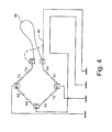
- Figure 4 illustrates a diagram of the Wheatstone bridge circuit incorporating the four pairs of first and second strain gauges of Figure 3 .
- Axial first strain gauges (A1, A3; A2, A4) are arranged in opposite legs of the Wheatstone bridge.
- transverse strain gauges (T1, T3; T2, T4) are arranged in opposite legs of the Wheatstone bridge.
- the temperature compensation wire or resistor (33) of Figure 3 can be electrically connected to external processing circuitry (40) in two different arrangements, depending on the desired sign of the temperature compensation or correction.
- the temperature compensation wire or resistor (33) is connected to external processing circuitry (40) at connection pad P4.
- the temperature compensation wire or resistor (33) is connected to external processing circuitry (40) at connection pad P5 (dashed line) resulting in a switch of the sign of the temperature compensation or correction value.
- a column load cell described herein comprises a load receiving surface and a load bearing column adjacent to the load receiving surface, the load bearing column comprising a plurality of surfaces separated by apertures in the load bearing column.
- a plurality of first strain gauges are coupled to the surfaces of the load bearing column separated by the apertures, wherein the first strain gauges are operable to determine axial strain.
- the column load cell further comprises a plurality of second strain gauges coupled to the surfaces of the load bearing column separated by the apertures, wherein the second strain gauges are operable to determine transverse strain.
- the apertures in the load bearing column direct the path of an applied load under the first and second strain gauges coupled to the surfaces of the load bearing column defined by the apertures. In some embodiments, all or substantially all of the applied load is directed through the load bearing column under the first and second strain gauges. In directing substantially all of the applied load through the load bearing column under the first strain gauges and the second strain gauges, the apertures can mitigate or inhibit load passing through the load bearing column undetected.
- the number of surfaces separated by the apertures in the load bearing column is at least 4. In some embodiments, an even number of surfaces greater than 4 are separated by the apertures in the load bearing column. In some embodiments, the number of surfaces separated by apertures in the load bearing column is a multiple of 4. Additionally, in some embodiments, at least one surface of the load bearing column is in facing opposition to another surface of the load bearing column. In some embodiments, each surface of the load bearing column is in facing opposition to another surface of the load bearing column. In some embodiments, each surface separated by the apertures in the load bearing column comprises first and second strain gauges.
- the load bearing column comprises at least four apertures. In some embodiments, the load bearing column comprises an even number of apertures greater than 4. In some embodiments, the number of apertures in the load bearing column is a multiple of 4. Moreover, in some embodiments, at least one aperture in the load bearing column is in facing opposition to another aperture across the load bearing column. In some embodiments, each aperture in the load bearing column is in facing opposition to another aperture in the load bearing column.
- the load receiving surface of the load cell comprises a plurality of load guides, wherein the load guides are aligned or substantially aligned with the first and second strain gauges. In being aligned with first and second strain gauges, the load guides, in some embodiments, are also aligned or substantially aligned with the surfaces of the load bearing column defined by the apertures.
- the load guides in some embodiments, work in conjunction with the apertures in directing substantially all of an applied load through the load bearing column under the first and second strain gauges.
- the load guides can comprise any structure or configuration described herein for load guides.
- first strain gauges and the second strain gauges are adjacent to one another on surfaces of the load bearing column defined by the apertures.
- the first and second strain gauges are adjacent to one another in a vertical format as illustrated in Figure 1 herein.
- the first and the second strain gauges are adjacent to one another in a lateral format.
- the load bearing column of a load cell comprises interior surfaces and exterior surfaces.
- the first and second strain gauges in some embodiments, are coupled to exterior surfaces of the load bearing column. In some embodiments, the first and second strain gauges are coupled to interior surfaces of the load bearing column. In some embodiments, the first and second strain gauges are coupled to interior and exterior surfaces of the lead bearing column.
- the load cell further comprises a Wheatstone bridge circuit incorporating the first strain gauges and the second strain gauges.
- the Wheatstone bridge circuit is a full Wheatstone bridge circuit.
- the Wheatstone bridge circuit in some embodiments, comprises a temperature compensation architecture.
- Figure 5 illustrates a perspective view of a column load cell according to one embodiment described herein.
- the column load cell (50) comprises a load receiving surface (51) and a load bearing column (52) adjacent to the load receiving surface (51).
- the load bearing column (52) comprises four surfaces (53) separated by apertures (54) in the load bearing column (52).
- each surface (53) separated by apertures (54) in the load bearing column (52) is in facing opposition to another surface (53).
- each aperture (54) in the load bearing column (52) is in facing opposition to another aperture (54) in the load bearing column (52).
- First and second strain gauge pairs (55) are coupled to the four surfaces (53) separated the apertures (54) in the load bearing column (52).
- a full Wheatstone bridge circuit (56) incorporating the first and second strain gauge pairs (55) encircles the exterior of the load bearing column (52).
- the wiring of the Wheatstone bridge (56) in Figure 5 has been cut away in areas of the apertures (54) to further illustrate the apertures (54).
- the full Wheatstone bridge circuit (56) has an architecture consistent with Figure 4 herein.
- the Wheatstone bridge circuit incorporating the first and second strain gauge pairs (55) is coupled to a continuous backing as described hereinabove and illustrated in Figure 3 .
- the column load cell (50) of Figure 5 further comprises four load guides (57) on the load receiving surface (51). As described herein, the load guides (57) are aligned or substantially aligned with the first and second strain gauge pairs (55). In being aligned with a first and second strain gauge pair (55), each of the four load guides (57) is also aligned with a respective one of the four surfaces (53) separated by the apertures (54) in the load bearing column (52).
- load guides and load bearing column apertures individually or in conjunction with one another direct the path of an applied load through the load bearing column under the first strain gauges and second strain gauges. In some embodiments, substantially all of the applied load is directed through the load bearing column under the first and second strain gauges. In directing substantially all of an applied load through the load bearing column under the first and second strain gauges, the load guides and column apertures individually or in conjunction with one another can mitigate or inhibit load passing through the load bearing column undetected or only partially detected.
- substantially all of the applied load is directed through the load bearing column under the first and second strain gauges irrespective of whether the load is applied on-center or off-axis/asymmetrically.
- first and second strain gauges aligned with load guides receiving greater load will sense or measure greater amounts of strain in comparison with first and second strain gauges aligned with load guides receiving reduced load.
- the sum of the strains measured by all of the first and second strain guides remains proportional to the applied load.
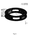
- Figure 6 illustrates compressive strain fields of a center loaded column load cell having the construction discussed and illustrated in Figure 5 .
- the load guides in conjunction with the apertures in the load bearing column direct substantially all of the applied load through the load bearing column under locations of the first and second strain gauges for measurement.
- Figure 7 illustrates compressive strain fields of an asymmetrically loaded column load cell having the construction discussed and illustrated in Figure 5 .
- the load guides and apertures in the load bearing column direct substantially all of the applied load through the load bearing column under locations of the first and second strain gauges for measurement.
- the sum of the strains measured by all of the first and second strain guides remains proportional to the applied load.
- Figure 8 illustrates transverse strain fields of a center loaded column load cell having the construction discussed and illustrated in Figure 5 while Figure 9 illustrates transverse strain fields of an asymmetrically loaded column load cell having the construction discussed and illustrated in Figure 5 .
- Load cells described herein can be constructed of any material not inconsistent with the objectives of the present invention.
- load cells described herein are constructed of various steels, including stainless steels.
- load cells are constructed of various alloys.
- load cells can be constructed of one or more polymeric materials including, but not limited to, fiber-reinforced polymeric materials.
- a load bearing column having an annular or ring cross-sectional profile.
- a load bearing column can have any cross-sectional geometry not inconsistent with the objectives of the present invention.
- the load bearing column of a load cell described herein has a polygonal shape or an elliptical shape.
- a load bearing column of a load cell described herein defines an open interior. As illustrated in Figures 2 and 5 , the annular load bearing column defines an open interior.
- the load guides comprise structures projecting from the load transfer surface. The structures, in some embodiments, project above the load receiving surface.
- load guides of a load transfer apparatus can have any structure or configuration described herein for load guides of a column load cell.
- a method of measuring a load comprises providing a column load cell comprising a load bearing column, a plurality of first strain gauges and second strain gauges coupled to surfaces of the load bearing column, the first strain gauges operable to determine axial strain and the second strain gauges operable to determine transverse strain, and a load receiving surface comprising a plurality of load guides aligned or substantially aligned with the first strain gauges and the second strain gauges.
- a load is applied to the column load cell and the path of the applied load is directed through the load bearing column under the first strain gauges and the second strain gauges with the load guides, wherein the first strain gauges and the second strain gauges sense strain resulting from the applied load.
- substantially all of the applied load is directed through the load bearing column under the first strain gauges and the second strain gauges by the load guides.
- the load is applied to the column load cell asymmetrically or in an off-axis manner.
- a method of measuring a load comprises providing a column load cell comprising a load receiving surface, a load bearing column adjacent to the load receiving surface, the load bearing column comprising a plurality of surfaces separated by apertures in the load bearing column, and a plurality of first strain gauges and second strain gauges coupled to the surfaces separated by the apertures, wherein the first strain gauges are operable to determine axial strain and the second strain gauges are operable to determine transverse strain.
- a load is applied to the column load cell and passed through the load bearing column under the first strain gauges and the second strain gauges, wherein the first and second strain gauges sense strain resulting from the applied load.
- substantially all of the applied load is directed through the load bearing column under the first strain gauges and the second strain gauges.
- the load receiving surface of the load cell comprises a plurality of load guides, wherein the load guides are aligned or substantially aligned with the first and second strain gauges.
- the load guides in some embodiments, are also aligned or substantially aligned with the surfaces of the load bearing column defined by the apertures.
- the load guides in some embodiments, work in conjunction with the apertures in directing substantially all of an applied load through the load bearing column under the first and second strain gauges.
- a method of measuring a load comprises providing a column load cell comprising a load bearing column and a plurality of strain gauges coupled to the load bearing column and coupling a load transfer apparatus to the load cell, the load transfer apparatus comprising a load transfer surface comprising a plurality of load guides, the load guides having a spacing on the load transfer surface substantially aligning the load guides with the strain gauges of the load cell.
- a load is applied to the load transfer apparatus and passed through the load transfer apparatus to the load cell.
- the path of the applied load is directed with the load guides through the load bearing column of the load cell under the first strain gauges and the second strain gauges, wherein the first and second strain gauges sense strain resulting from the applied load.
- substantially all of the load is directed through the load bearing column under the first and second strain gauges by the load guides of the load transfer apparatus.
- methods of measuring a load described herein further comprise adding the strains sensed by the first strain gauges and the second strain gauges to provide a strain summation, wherein the strain summation is proportional to the applied load.
- the load cell can have any construction described herein.
- a method of making a load cell comprises providing a load bearing column and a load receiving surface adjacent to the load bearing column, coupling a plurality of strain gauges to surfaces of the load bearing column and providing a plurality of load guides on the load receiving surface, the load guides substantially aligned with the strain gauges.
- a method of making a load cell comprises providing a load bearing column and a load receiving surface adjacent to the load bearing column, forming a plurality of apertures in the load bearing column to provide a plurality of separated surfaces and coupling a plurality of strain gauges to the surfaces of the load bearing column separated by the apertures.
Landscapes
- Physics & Mathematics (AREA)
- General Physics & Mathematics (AREA)
- Force Measurement Appropriate To Specific Purposes (AREA)
Applications Claiming Priority (1)
| Application Number | Priority Date | Filing Date | Title |
|---|---|---|---|
| US13/302,879 US20130126249A1 (en) | 2011-11-22 | 2011-11-22 | Load cell and applications thereof |
Publications (2)
| Publication Number | Publication Date |
|---|---|
| EP2597441A2 true EP2597441A2 (fr) | 2013-05-29 |
| EP2597441A3 EP2597441A3 (fr) | 2014-01-22 |
Family
ID=47263119
Family Applications (1)
| Application Number | Title | Priority Date | Filing Date |
|---|---|---|---|
| EP12193690.0A Withdrawn EP2597441A3 (fr) | 2011-11-22 | 2012-11-21 | Cellule de charge et leurs applications |
Country Status (2)
| Country | Link |
|---|---|
| US (1) | US20130126249A1 (fr) |
| EP (1) | EP2597441A3 (fr) |
Cited By (1)
| Publication number | Priority date | Publication date | Assignee | Title |
|---|---|---|---|---|
| WO2016146275A3 (fr) * | 2015-03-16 | 2016-11-03 | Robert Bosch Gmbh | Dispositif de mesure pour détecter des déformations |
Families Citing this family (9)
| Publication number | Priority date | Publication date | Assignee | Title |
|---|---|---|---|---|
| US10225629B2 (en) * | 2013-11-25 | 2019-03-05 | Chi Hung Louis Lam | System for monitoring condition of adjustable construction temporary supports |
| CN103743506B (zh) * | 2014-01-16 | 2016-03-23 | 上海理工大学 | 一种载荷测量装置及其测量方法 |
| JP6342971B2 (ja) * | 2016-11-14 | 2018-06-13 | ファナック株式会社 | 力検出装置及びロボット |
| US20190015702A1 (en) * | 2017-07-17 | 2019-01-17 | Aurora Flight Sciences Corporation | Dynamic Load Sensor for Microgravity |
| JP2020051817A (ja) * | 2018-09-25 | 2020-04-02 | 日立オートモティブシステムズ株式会社 | 荷重センサ、電動ブレーキ |
| CN112211911A (zh) * | 2020-10-28 | 2021-01-12 | 北京交通大学 | 滚动轴承运行状态在位监测用轴承座改造结构及方法 |
| US12000740B2 (en) * | 2020-11-17 | 2024-06-04 | Board Of Trustees Of Michigan State University | Sensor apparatus |
| US11763109B2 (en) * | 2021-01-27 | 2023-09-19 | Paratech, Incorporated | Electronic strut monitor |
| CN115435878B (zh) * | 2022-09-09 | 2025-06-27 | 郑州衡量科技股份有限公司 | 一种抗剪切动态称重传感器 |
Family Cites Families (12)
| Publication number | Priority date | Publication date | Assignee | Title |
|---|---|---|---|---|
| US3136157A (en) * | 1960-07-11 | 1964-06-09 | Toledo Scale Corp | Load cell apparatus |
| US3678753A (en) * | 1970-07-28 | 1972-07-25 | Microdot Inc | Pressure transducer |
| US4065962A (en) * | 1974-10-29 | 1978-01-03 | Gse, Inc. | Load cell |
| US4094192A (en) * | 1976-09-20 | 1978-06-13 | The Charles Stark Draper Laboratory, Inc. | Method and apparatus for six degree of freedom force sensing |
| US4423793A (en) * | 1981-10-23 | 1984-01-03 | Interface, Inc. | Load cell of integral unitary construction containing a solid disc-shaped measuring section |
| US4804053B1 (en) * | 1987-11-10 | 1996-09-03 | Flintab Ab | Rocker pin load cell |
| KR100199691B1 (ko) * | 1997-05-19 | 1999-06-15 | 김동진 | 6분력 로드셀 |
| GB2370122B (en) * | 2000-12-16 | 2005-04-27 | Senstronics Ltd | Temperature compensated strain gauge |
| US6711960B2 (en) * | 2001-05-31 | 2004-03-30 | Teac Corporation | Compact load cell with arm tension absorption means and arm reinforcement means |
| US6792815B2 (en) * | 2002-05-08 | 2004-09-21 | The Timken Company | Multiaxis ring load cell |
| US20060107761A1 (en) * | 2004-11-16 | 2006-05-25 | Meyer Richard A | Multi-axis load cell body |
| DE102009022343B4 (de) * | 2009-05-15 | 2016-04-28 | Brosa Ag | Kraftmesssystem zum Messen von Schub- bzw. Druckkräften, insbesondere bei Spreadern |
-
2011
- 2011-11-22 US US13/302,879 patent/US20130126249A1/en not_active Abandoned
-
2012
- 2012-11-21 EP EP12193690.0A patent/EP2597441A3/fr not_active Withdrawn
Non-Patent Citations (1)
| Title |
|---|
| None |
Cited By (1)
| Publication number | Priority date | Publication date | Assignee | Title |
|---|---|---|---|---|
| WO2016146275A3 (fr) * | 2015-03-16 | 2016-11-03 | Robert Bosch Gmbh | Dispositif de mesure pour détecter des déformations |
Also Published As
| Publication number | Publication date |
|---|---|
| US20130126249A1 (en) | 2013-05-23 |
| EP2597441A3 (fr) | 2014-01-22 |
Similar Documents
| Publication | Publication Date | Title |
|---|---|---|
| EP2597441A2 (fr) | Cellule de charge et leurs applications | |
| CN105091731B (zh) | 可测量表面应变轴向偏导的轴向偏差双敏感栅叉指型金属应变片 | |
| US8042413B2 (en) | Transverse force measurement | |
| EP3025129B1 (fr) | Interface sous forme de circuit souple pour extensomètres | |
| CN105066870A (zh) | 可测量表面应变轴向偏导的轴向偏差全桥双叉指型金属应变片 | |
| US3376537A (en) | Shear strain load cell | |
| CN104685314B (zh) | 应变变送器 | |
| EP2081007B1 (fr) | Goupille de mesure de charge | |
| JP2017096863A (ja) | 構造物の亀裂発生検出システム及びそれに用いるひずみセンサ | |
| US7347109B2 (en) | Load cell with foil strain gauge | |
| JP6611762B2 (ja) | ひずみゲージ及び多軸力センサ | |
| CN119984615A (zh) | 多维力传感器及加工方法 | |
| CN103353365A (zh) | 一种点接触柱销式测力传感器 | |
| CN119984616A (zh) | 多维力传感器及加工方法 | |
| JP2014085259A (ja) | ひずみゲージ、ひずみ測定装置及びひずみゲージ式変換器 | |
| CN105547132B (zh) | 可测量偏置敏感栅中心横向偏导的横向分布三敏感栅金属应变片 | |
| CN204924166U (zh) | 可测量表面应变横向偏导的横向偏差双敏感栅叉指型金属应变片 | |
| JP6767559B2 (ja) | ひずみゲージ及び多軸力センサ | |
| CN119984587A (zh) | 一体式应变片 | |
| CN119984586A (zh) | 一体式应变片 | |
| CN105547134B (zh) | 可测量偏置敏感栅外侧横向偏导的横向偏差三敏感栅叉指金属应变片 | |
| CN105423896B (zh) | 可测量双侧片外横向偏导的横向偏差六敏感栅全桥混合叉指金属应变片 | |
| CN105371750B (zh) | 可测量单侧片外轴向偏导的轴向分布五敏感栅中密叉指金属应变片 | |
| CN105423906B (zh) | 可测量单侧片外横向偏导的横向分布五敏感栅边叉指金属应变片 | |
| CN105466330B (zh) | 可测量偏置敏感栅外侧横向偏导的横向分布三敏感栅金属应变片 |
Legal Events
| Date | Code | Title | Description |
|---|---|---|---|
| PUAI | Public reference made under article 153(3) epc to a published international application that has entered the european phase |
Free format text: ORIGINAL CODE: 0009012 |
|
| 17P | Request for examination filed |
Effective date: 20121121 |
|
| AK | Designated contracting states |
Kind code of ref document: A2 Designated state(s): AL AT BE BG CH CY CZ DE DK EE ES FI FR GB GR HR HU IE IS IT LI LT LU LV MC MK MT NL NO PL PT RO RS SE SI SK SM TR |
|
| AX | Request for extension of the european patent |
Extension state: BA ME |
|
| PUAL | Search report despatched |
Free format text: ORIGINAL CODE: 0009013 |
|
| AK | Designated contracting states |
Kind code of ref document: A3 Designated state(s): AL AT BE BG CH CY CZ DE DK EE ES FI FR GB GR HR HU IE IS IT LI LT LU LV MC MK MT NL NO PL PT RO RS SE SI SK SM TR |
|
| AX | Request for extension of the european patent |
Extension state: BA ME |
|
| RIC1 | Information provided on ipc code assigned before grant |
Ipc: G01L 1/22 20060101AFI20131216BHEP |
|
| STAA | Information on the status of an ep patent application or granted ep patent |
Free format text: STATUS: THE APPLICATION IS DEEMED TO BE WITHDRAWN |
|
| 18D | Application deemed to be withdrawn |
Effective date: 20140723 |