EP2597458B1 - Réflectomètre portable et procédé de caractérisation de miroirs de centrales thermosolaires - Google Patents
Réflectomètre portable et procédé de caractérisation de miroirs de centrales thermosolaires Download PDFInfo
- Publication number
- EP2597458B1 EP2597458B1 EP11809308.7A EP11809308A EP2597458B1 EP 2597458 B1 EP2597458 B1 EP 2597458B1 EP 11809308 A EP11809308 A EP 11809308A EP 2597458 B1 EP2597458 B1 EP 2597458B1
- Authority
- EP
- European Patent Office
- Prior art keywords
- mirror
- measurement
- portable reflectometer
- portable
- reflection
- Prior art date
- Legal status (The legal status is an assumption and is not a legal conclusion. Google has not performed a legal analysis and makes no representation as to the accuracy of the status listed.)
- Active
Links
Images



Classifications
-
- G—PHYSICS
- G01—MEASURING; TESTING
- G01N—INVESTIGATING OR ANALYSING MATERIALS BY DETERMINING THEIR CHEMICAL OR PHYSICAL PROPERTIES
- G01N21/00—Investigating or analysing materials by the use of optical means, i.e. using sub-millimetre waves, infrared, visible or ultraviolet light
- G01N21/17—Systems in which incident light is modified in accordance with the properties of the material investigated
- G01N21/47—Scattering, i.e. diffuse reflection
-
- G—PHYSICS
- G01—MEASURING; TESTING
- G01M—TESTING STATIC OR DYNAMIC BALANCE OF MACHINES OR STRUCTURES; TESTING OF STRUCTURES OR APPARATUS, NOT OTHERWISE PROVIDED FOR
- G01M11/00—Testing of optical apparatus; Testing structures by optical methods not otherwise provided for
- G01M11/005—Testing of reflective surfaces, e.g. mirrors
-
- G—PHYSICS
- G01—MEASURING; TESTING
- G01N—INVESTIGATING OR ANALYSING MATERIALS BY DETERMINING THEIR CHEMICAL OR PHYSICAL PROPERTIES
- G01N21/00—Investigating or analysing materials by the use of optical means, i.e. using sub-millimetre waves, infrared, visible or ultraviolet light
- G01N21/17—Systems in which incident light is modified in accordance with the properties of the material investigated
- G01N21/55—Specular reflectivity
-
- G—PHYSICS
- G01—MEASURING; TESTING
- G01N—INVESTIGATING OR ANALYSING MATERIALS BY DETERMINING THEIR CHEMICAL OR PHYSICAL PROPERTIES
- G01N2201/00—Features of devices classified in G01N21/00
- G01N2201/02—Mechanical
- G01N2201/022—Casings
- G01N2201/0221—Portable; cableless; compact; hand-held
-
- G—PHYSICS
- G01—MEASURING; TESTING
- G01N—INVESTIGATING OR ANALYSING MATERIALS BY DETERMINING THEIR CHEMICAL OR PHYSICAL PROPERTIES
- G01N2201/00—Features of devices classified in G01N21/00
- G01N2201/06—Illumination; Optics
- G01N2201/062—LED's
- G01N2201/0625—Modulated LED
-
- G—PHYSICS
- G01—MEASURING; TESTING
- G01N—INVESTIGATING OR ANALYSING MATERIALS BY DETERMINING THEIR CHEMICAL OR PHYSICAL PROPERTIES
- G01N2201/00—Features of devices classified in G01N21/00
- G01N2201/06—Illumination; Optics
- G01N2201/062—LED's
- G01N2201/0627—Use of several LED's for spectral resolution
Definitions
- the present invention falls within the technology of optical measuring equipment or instruments.
- This equipment relates to portable equipment for spectral characterization and in the field of coefficients of reflection of flat mirrors or with a certain degree of curvature, whether these are heliostat mirrors, Stirling, Fresnel... etc., all of these used in collectors for obtaining solar thermal energy.
- This equipment includes all the components needed to take this measurement, including data processing and sending them to a computer for storage.
- the value of the coefficient of reflectivity of the mirrors installed in these systems plays an important role in the performance of power plants that generate solar thermal energy. Furthermore, knowledge of these reflectivity values allows, together with information on environmental conditions of the area and other technical data of the plants, to forecast the power that will be generated in the near future in order for firms to properly manage energy resources.
- a reflectometer For the operation and maintenance of electric energy production facilities, due to the large number of mirrors installed, it is convenient to have equipment that allows the characterization of reflectivity of each mirror quickly, conveniently and easily.
- the equipment that carries out a measurement of this type is called a reflectometer.
- the equipment Given the optical characteristics of the solar energy absorbing elements which are included in these plants (maximum energy absorption and minimum energy losses, which determine dependencies of the optical parameters with the wavelength), the equipment must provide measurements of the mirrors according to the wavelength.
- the equipment must provide precise measurement of reflection value extremes close to the unit, generally in unfavorable environmental conditions, since the ambient light intensity will usually be high and even exceed in some cases, the signal to be measured itself.
- the requirement of high precision of the measurements is essential in solar thermal technology to maintain the efficiency in plants that produce electricity.
- the reflection in the mirrors can be of two characters; diffuse and specular. Diffuse reflection is omnidirectional, unlike specular reflection in which the beam is reflected at a reflection angle equal to the angle of incidence. Due to the dirt that is deposited on the surface of the mirrors of the plant, the reflection of sunlight will have diffuse and specular components, specular reflection being useful only from the viewpoint of power generation, since it is the only one that will concentrate on the absorber element. Therefore, the equipment should minimize the contribution of diffuse reflection on the measurement of the reflection coefficient of the mirrors.
- the equipment must be able to correctly measure the set of types of mirrors commonly used in the power plants. Specifically, it must be able to correctly measure flat mirrors, mirrors with a certain degree of spherical curvature, parabolic and cylinder-parabolic mirrors of different thicknesses without equipment adjustments.
- a conventional reflectometer uses a broad spectrum light source and a variable filtering element that allows for sequentially select different wavelengths, such as a movable diffraction grating followed by a narrow slit. This option allows for varying the wavelength in a virtually continuous way, but in turn, results in a more complex and delicate system, with a low measurement dynamic range as the power of the input light that is achieved is very low. Furthermore, conventional equipment does not minimize the contribution of diffuse reflection, and in fact, in some cases it is of interest to collect all the scattered light and integrating spheres in detection are implemented.
- the patent US 5815254 describes a spectrophotometer device that can work in transmission measurement mode and reflection measurement mode. It uses a source of white light, halogen or Xe, optical fibers to carry the illumination light beam from the sample onto the sample surface, and a spectral analysis based on diffraction grating and a detector line.
- the patent US 3862804 describes double beam reflectometer equipment with switching mirror included in each measurement, the correction with the standard measurement, and integrating sphere to include in the measurement of scattered light reflection.
- the system uses white light, the monochromator for wavelength selection, illumination with collimated beams and integrating sphere in the detection which means that all the scattered light is collected and measured in the detection.
- the patent US 4687329 describes spectrophotometer equipment which uses a broad spectrum source, in this case ultraviolet, and various filters in fixed positions to perform a spectral measurement on a number of discrete points.
- a broad spectrum source in this case ultraviolet
- various filters in fixed positions to perform a spectral measurement on a number of discrete points.
- a collection source of light sources of different wavelengths is used.
- multiple light emitting diodes LED are used simultaneously to perform a transmission measurement for the detection of various analytes in blood.
- one true spectral measurement is not performed, but rather several simultaneous measurements at a few different wavelengths.
- the beam is chopped and filtered by an electronic circuit to make it immune to fluorescent and other ambient light conditions except bright sunlight. None of the above equipment or other similar equipment meet the requirements necessary for measurement in the field of mirrors for solar collectors, either by range, sensitivity and/or mechanical configuration.
- the present invention takes into account the specific characteristics of the problem mentioned above, to obtain portable, robust, and easy to use equipment, that takes measurements quickly, with an adequate sensitive and dynamic range, with sufficient tolerance in curvature and thickness of the mirror to be measured and that minimizes the contribution of the diffuse reflection in the measurement
- the equipment takes the measurement of the coefficient of specular reflection of mirrors at different wavelengths, these determined by light emitting diodes LED.
- the mirrors object of characterization may be flat or curved, and may be first or second side mirrors with different thicknesses.
- Each wavelength constitutes a reflectance measurement optical channel in the equipment.
- the device For each reflectance measurement optical channel, the device performs two measurements, a reference measurement on a percentage of the light emitted by the LED and a direct measurement of the light specularly reflected by the mirror.
- the equipment performs simultaneous measurement of reference and direct in each measurement optical channel to adequately correct the variations in the power of the LED emission of said channel.
- the number of optical channels can be variable, with at least one and covering the desired spectral range with commercial LEDs in the ultraviolet range to near infrared. With the usual requirements for spectral characterization of a facility of solar thermal energy production, it may be sufficient to have about five measurement wavelengths.
- the angle of incidence of the light beam from the LED and the collection angle of the light beam reflected by the mirror is the same, to ensure measurement of specular reflection.
- the size of the illuminated area on the mirror determines the amount of scattered light that may be introduced on the reflectance measurement. To minimize this amount of undesired scattered light, the illuminated area on the mirror should be as small as possible.
- the numerical output aperture of the illumination beam from the LED is limited, by a diaphragm with a certain diameter and length, placed at the output of the LED and oriented on the optical axis of the system to ensure the angle of incidence of the light beam required on the mirror.
- the beam reflected by the mirror in specular reflection is collected by a lens which focuses the beam onto a detector for the direct measurement of the specularly reflected light by the mirror.
- This lens and detector system is oriented on the optical axis of the system to ensure the collection angle of the light beam in specular reflection.
- the size of the lens relative to the size of the beam at this point determines the tolerance of the system against the curvature of the mirror and against the position of the mirror surface with respect to the measuring equipment determined by the thickness of the glass that protects the mirror face.
- the size of the lens is not larger than the size of the beam at that point, the conditions of curvature of the mirror or of the thickness of the mirror for the correct measurement, would be unique and variations thereof would mean that not all of the light beam specularly reflected by the mirror would be collected by the lens and reached the detector, leading to an error of reflectance measurement.
- a size of lens that is twice the size of the beam at that point may be sufficient.
- the combination of the optical parameters of the numerical aperture of the illumination beam, lens size and focal length of the lens determines the relative positions of the set of LED, mirror, lens and detector and hence the size of the equipment.
- the acquisition system To obtain a measurement with high sensitivity, that allows accurately resolving values of the reflection coefficients very close to unit, it is necessary for the acquisition system to have a relation signal to noise ratio large enough. Since the optical signal is primarily from the environmental sunlight, that is, it is a high intensity signal, it is essential to perform some type of treatment to said signal that allows for the signal to noise ratio to be high. It is most appropriate in this case that the signal processing by implementing an extraction algorithm such as synchronous detection or lock-in. To perform a treatment of this type, it is necessary that the signal measurement can be easily distinguished from background noise, which is usually achieved by applying some type of modulation thereof.
- Another essential feature in equipment of this type is the possibility of treatment and export of data in a convenient and flexible way, that they can be stored in the manner deemed most appropriate. This can be solved through wireless communication with a standard network protocol, by means of conventional cable connection type via USB port or also by using conventional computer memory sticks.
- One of the advantages and advancements provided by the disclosure is the fact that the system is capable of performing measurements of reflectance of the mirrors with ambient light and in the field, without special darkness or protection conditions.
- Another of the advantages and advancements provided by the invention is the fact that the system is able to characterize mirrors of different curvatures and different thicknesses with a high tolerance in these parameters without needing to make any adjustments in the equipment.
- Another very important advancement is to minimize the contribution of reflected scattered light in the measurement, a point of great interest in measurements in plants where the dirt on the mirrors is relevant.
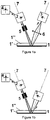
- the mirrors (1) for solar collectors are commonly second face mirrors, in such a way that on the mirror surface, there is a glass with a thickness of between approximately 3mm and 5mm. These mirrors may be flat, spherically curved in the case of power plants for solar concentration at a point, or cylinder-parabolic, as in the case of solar concentration on core tubes.
- the mirror must have a very high reflection coefficient in the solar spectrum.
- the reflection measurement is obtained from measurements performed by the reflection detector (3) after the beam generated by the LED emitter (2) passes through the outer glass (1 "), is reflected on the mirror surface specularly (1 ') and passes through the outer glass (1 ") again.
- the LED (light emitting diode) (2) is oriented on the optical axis (7) of the system with a defined angle of incidence on the mirror (1), so that it coincides with the direction of the maximum emission of the LED with the orientation of the mirrored surface.
- the angle of incidence is 15°.
- This LED output beam in the direction of the mirror is limited in numerical aperture by a diaphragm (5) to ensure the beam size on the mirror surface.
- the system obtains a reference signal from the measurement of part of the light emitted by the LED in a different direction by means of the detector (4).
- the specular reflection of the beam on the mirror is collected by the lens (6) of double the size of the beam size at this point.
- This lens (6) is oriented according to the optical axis of the system, and focuses the light beam on the direct light measuring detector (3).
- Figures 2 and 3 show the mechanical aspect of the embodiment, not including the upper and front casing that protect the components. Included in the figures are the two lateral casings (9) which form, the support pieces for the equipment on the mirror and allow repetitive positioning at the height of optical system on the mirror to be characterized (1) in a simple and fast way.
- the piece (8) that contains the emitters, detectors, diaphragms and lenses for measuring the reflection can also be distinguished.
- the arrangement of the reflectance optical channels for reflectance measurement is in a line.
- the emitters (2) and direct light detectors (3) are placed on the upper face of the piece (8).
- the lenses (6) and diaphragms (5) are placed which, in this embodiment, are holes made on the same piece that connects to the LED position.
- the rubber O-rings (10) placed along the lower profile of the support pieces (9) ensure the correct support of the equipment on the mirror without damaging it.
- the reference detectors (4) are placed on the LED emitters (2) for measuring the light beam emitted by them in that direction, and are supported on the same printed circuit board (11) containing the electronics of the equipment.
- Figure 6 shows the complete diagram including the system for data acquisition and processing (12), the data processing system and equipment control (14), the data storage system (15) and the interface user system (23).
- the data acquisition and processing system (12) consists of a signal (21) of the emitters which is modulated, by sinusoidally varying the power supply current of the LEDs (each of them in a different time). This modulation allows for extracting the signal of interest in the detectors (3, 4), filtering out all frequency components except for that corresponding to the LED being measured at each moment.
- the modulation signals of the LEDs (21) are generated in the modulation generator (18) by a local oscillator.
- LED's have been chosen at wavelengths of 435, 525, 650, 780, 949 that cover the spectral region of interest plus an LED that emits white light for a faster integrated measurement of the visible spectrum.
- the photodetectors (3, 4) are followed by two amplification stages (19) whose gain depends on the value of the resistances they have.
- One of these resistances may be a digital potentiometer whose value can be controlled via software, allowing for the adjustment of the gain of each channel at any time using the digital outputs (20) of the analog-to-digital conversion system (17).
- the frequency filtering is carried out by synchronous detection (lock-in) in the signal detection and processing system (12).
- the synchronous detection system involves amplification of the signal exclusively to the modulation frequency, whose frequency is obtained from an electrical reference signal.
- the synchronous detection can be analog or digital.
- the signals detected in the photodetectors (3.4) are processed in a lock-in amplifying analog circuit, whose output (a continuous signal) is directed to the analog-to-digital converter (17).
- the analog-to-digital conversion is performed with a data acquisition board DAQ which also responsible for the control via digital outputs (20) of the power supply of the boards of the emitters (2) and detectors (3, 4), as well as of the selection of the optical channel to be measured at each time.
- the first step is the digitization of the modulation signals (21) and those from the photodetectors (3, 4) by means of the DAQ for subsequent introduction into a digital processing system of the signal, such as a DSP (digital signal processor), an FPGA (Field Programmable Gate Array), a microcontroller capable of digital signal processing, or a computer that performs synchronous detection algorithm.
- a digital processing system of the signal such as a DSP (digital signal processor), an FPGA (Field Programmable Gate Array), a microcontroller capable of digital signal processing, or a computer that performs synchronous detection algorithm.
- the detection and signal processing system (12) communicates with the data processing and equipment control system (14) which can be a conventional external computer.
- control computer by a system built into the actual equipment, such as a microcontroller, which can also be used to replace the analog-to-digital converter (17).
- a system built into the actual equipment such as a microcontroller, which can also be used to replace the analog-to-digital converter (17).
- the same element used to perform the synchronous processing can replace both the DAQ and the control computer (14).
- the processor element can also replace the local oscillator used in the modulation generator (18), which eliminates the need to acquire the modulation signal (21), as it is generated by the same processing system.
- Figure 5 shows the external appearance of the equipment in an embodiment with all the systems built into the equipment.
- a program installed on the data processing equipment control system allows for the use of commands (24) which programmed into the signal detection and processing system (12) to perform all the necessary functions in the measurement process, including the measurement channel selection for the corresponding LED modulation and reading the data (25) obtained for further processing and storage. It also enables the storage of relevant data in the storage system (15) and management of the data and commands with the user interface system (23).
- a specific example of measurement corresponding to a flat mirror is shown in Figure 5 .
- the equipment operation method comprises the following steps for obtaining the reflection and transmission coefficients of the tubes:
- a second example is proposed, which is identical to the first example except for the arrangement of the optical channels which is in a circle instead of being in line as shown in Figure 4 .
- the illumination point on the mirror surface is the same for all the LED diodes and the reflectance measurement of each channel corresponds to the same point on the mirror.
- a third example is proposed, which is identical to the first example except that the lens is removed in each measurement channel and in its place, the detector is directly placed as shown in Figure 1b .
- the specular reflection of the beam on the mirror leads directly to the direct light measuring detector (3).
- a fourth example is proposed, which is identical to the second example except that the lens is removed in each measurement channel and in its place, the detector is directly placed as shown in Figure 1 b.
- the specular reflection in the mirror of the beam leads to the direct light measuring detector (3).
Landscapes
- Analytical Chemistry (AREA)
- General Physics & Mathematics (AREA)
- Physics & Mathematics (AREA)
- Chemical & Material Sciences (AREA)
- General Health & Medical Sciences (AREA)
- Biochemistry (AREA)
- Life Sciences & Earth Sciences (AREA)
- Health & Medical Sciences (AREA)
- Immunology (AREA)
- Pathology (AREA)
- Investigating Or Analysing Materials By Optical Means (AREA)
- Testing Of Optical Devices Or Fibers (AREA)
- Optical Elements Other Than Lenses (AREA)
Claims (25)
- Réflectomètre portable pour la caractérisation de miroirs de collecteurs solaires (1), plus spécifiquement pour la mesure spectrale de la réflexion spéculaire de miroirs collecteurs solaires, comprenant:- un module qui effectue la mesure du coefficient de réflexion du miroir (13) comprenant une pluralité de diodes électroluminescentes (2) en tant que sources optiques et une pluralité de photodétecteurs de mesure (3) ainsi qu'au moins un photodétecteur de référence (4) pour obtenir un signal de référence de la lumière émise par les diodes électroluminescentes (2) dans une direction différente de celle de la lumière incidente sur le miroir;- une pluralité de diaphragmes (5) limitant, en dimension et en ouverture, les faisceaux lumineux de sortie des diodes électroluminescentes incidentes sur le miroir, pour assurer la dimension de la zone éclairée sur la surface du miroir, limitant ainsi la contribution de la réflexion diffuse dans la mesure;- Une pluralité de lentilles (6) situées dans le trajet du faisceau lumineux réfléchi après la réflexion spéculaire du faisceau sur le miroir qui sont orientées sur l'axe optique du faisceau réfléchi, et qui focalisent les faisceaux lumineux sur les photodétecteurs (3) afin d'avoir une tolérance en courbure et en épaisseur des miroirs;- un système électronique pour acquérir des signaux (12) délivrés par les photodétecteurs et pour traiter ces signaux (12) pour obtenir des valeurs spectrales, le système électronique comprenant des moyens de détection synchrone (16) utilisant un générateur électronique de modulation (18) et un traitement analogique ou numérique en combinaison avec un convertisseur analogique-numérique (17);- Un système de traitement de données et de commande d'équipement (14) qui fournit des valeurs de réflectance globales au moyen de la pondération des valeurs spectrales obtenues avec le poids correspondant des longueurs d'onde dans le spectre solaire;- un système de stockage des données d'intérêt (15);- un système d'interface d'utilisateur (23);- un système de communication entre les systèmes précédents (12, 13, 14, 15, 23);- un boîtier extérieur, une pièce portante (8) et des boîtiers latéraux (9) pour maintenir la pièce portante (8), dans lequel des canaux optiques pour mesurer la réflectance définie par la pluralité de diodes électroluminescentes de mesure (2) et la pluralité de photodétecteurs de mesure (3) sont agencés dans une ligne;dans lequel les diodes électroluminescentes (2) et les photodétecteurs de mesure (3) sont disposés sur la surface supérieure de la pièce portante (8) et les lentilles (6) et les diaphragmes (5) sont agencés sur la surface inférieure de la pièce portante (8), lesdits diaphragmes étant définis par des trous dans la pièce portante (8) pour fournir des trajets de lumière depuis les diodes électroluminescentes (4) vers la surface inférieure de la pièce portante (8); La pluralité de boîtiers de support latérales (9) comprend des joints toriques en caoutchouc (10) placés le long du profil inférieur des boîtiers de support latéraux (9) pour assurer le bon support du réflectomètre sur le miroir sans endommager le miroir;
une carte de circuit imprimé (11) contenant l'électronique du réflectomètre; par laquelle au moins un photodétecteur de référence (4) est supporté sur la carte de circuit imprimé (11) qui est disposée en amont des diodes électroluminescentes (2) et au moins un photodétecteur de référence (4) mesure le faisceau lumineux émis par les diodes électroluminescentes (2) dans une direction ascendante. - Réflectomètre portable selon la revendication 1 caractérisé en ce que les photodétecteurs (3, 4) sont suivis de deux étapes d'amplification (19).
- Réflectomètre portable selon la revendication 2 caractérisé en ce que l'une au moins des deux étapes d'amplification présent un gain qui peut être varié à n'importe quel moment au moyen des commandes logiciels.
- Réflectomètre portable selon la revendication 1 caractérisé en ce que le nombre de diodes émettrices de lumière est compris entre 1 et 24 et dans le domaine spectral entre 300 et 2.500 nm correspondant au spectre solaire.
- Réflectomètre portable selon la revendication 4 caractérisé en ce que 5 LEDs sont installées avec des longueurs d'onde 435, 525, 650, 780 et 949 nm, ainsi qu'une LED émettant de la lumière blanche.
- Réflectomètre portable selon la revendication 1 caractérisé en ce que l'agencement des émetteurs est tel qu'ils sont placés dans une configuration en ligne.
- Réflectomètre portable selon la revendication 1 caractérisé en ce que l'agencement des émetteurs est tel qu'ils sont placés dans une configuration circulaire
- Réflectomètre portable selon la revendication 1 caractérisé en ce que chaque émetteur est placé orienté de telle sorte que la direction d'émission du faisceau lumineux maximale coïncide avec l'axe optique d'incidence du système sur le miroir.
- Réflectomètre portable selon la revendication 1 caractérisé en ce que, aussi la lentille (6) que le photodétecteur (3), ils se trouvent orientés suivant l'axe optique du système (7) défini par la réflexion spéculaire.
- Réflectomètre portable selon la revendication 1 caractérisé en ce que la taille de la lentille (6) est deux fois la taille du faisceau dans ce point-là.
- Réflectomètre portable selon la revendication 10 caractérisé en ce que la lentille a une focale maximale de 15 mm et un diamètre maximal de 1,27 mm (une demiepouce), ce qui permet d'obtenir un équipement portable et maniable.
- Réflectomètre portable selon la revendication 1 caractérisé en ce que le générateur de modulation (18) est un oscillateur local.
- Réflectomètre portable selon la revendication 1 caractérisé en ce que la conversion analogique/numérique (17) est effectuée avec une carte d'acquisition de données DAQ ou avec un microcontrôleur.
- Réflectomètre portable selon la revendication 1 caractérisé en ce que le générateur de modulation (18) est un système quelconque de traitement numérique tel qu'un DSP (processeur de signal numérique), une FPGA (Field Programmable Gate Array), un microcontrôleur avec la capacité de traitement numérique du signal ou un ordinateur.
- Réflectomètre portable selon la revendication 14 caractérisé en ce que le traitement du signal est réalisé avec n'importe quel système dé traitement numérique tel qu'un DSP (processeur de signal numérique), une FPGA (Field Programmable Gate Array), un microcontrôleur avec la capacité de traitement numérique du signal ou un ordinateur.
- Réflectomètre portable selon la revendication 1 caractérisé en ce que le système de traitement numérique utilisé lors de la détection synchrone (16) et dans le générateur de modulation (18) est le même.
- Réflectomètre portable selon la revendication 1 caractérisé en ce que le système de traitement des données et de commande de l'équipement (14) est un ordinateur externe au réflectomètre portable.
- Réflectomètre portable selon la revendication 17 caractérisé en ce que la communication entre l'équipement et l'ordinateur externe est réalisée par voie sans fil ou par câble.
- Réflectomètre portable selon la revendication 17 caractérisé en ce que le système de stockage des données d'intérêt (15) est situé dans l'ordinateur externe au réflectomètre portable.
- Réflectomètre portable selon la revendication 17 caractérisé en ce que le système d'interface d'utilisateur (23) est situé dans l'ordinateur externe au réflectomètre portable.
- Réflectomètre portable selon la revendication 1 caractérisé en ce que le système de traitement des données et de commande de l'équipement (14) est un système intégré dans l'équipement lui-même.
- Réflectomètre portable selon la revendication 21 caractérisé en ce que le système intégré dans l'équipement remplace l'un au moins des composants utilisés aussi lors des procédés du système de détection et de traitement du signal (12), ces composants étant le détecteur synchrone (16), le convertisseur analogique/numérique (17) et le générateur de modulation (18), ainsi que ceux du système de stockage (15) et ceux du système d'interface d'utilisateur (23).
- Réflectomètre portable selon la revendication 21, caractérisé en ce que le système intégré dans l'équipement remplace le système de stockage (15) et/ou le système d'interface d'utilisateur (23) remplissant leurs fonctions.
- Procédé de caractérisation de miroirs de centrales thermosolaires en utilisant le réflectomètre portable des revendications précédentes caractérisé en ce que la mesure du coefficient de réflexion des miroirs comprend les étapes suivantes:1. positionner le réflectomètre de telle sorte qu'il prend appui de manière stable sur le miroir;2. allumer les émetteurs de l'équipement;3. d'une manière consécutive, moduler chacun des émetteurs de LED à la fréquence de mesure;4. normaliser les données obtenues dans le détecteur de réflexion correspondant au LED modulé par un signal de référence en plaçant les détecteurs de référence (4) sur les émetteurs de LED (2) pour mesurer le faisceau lumineux émis par les émetteurs de LED (2) et supportés sur une carte de circuit imprimé (11) contenant l'électronique de l'équipement, afin d'éliminer l'influence des variations de l'intensité d'émission de chaque LED;5. limiter en ouverture numérique par un diaphragme (5) ce faisceau de sortie de l'émetteur LED dans le sens du miroir pour assurer la taille du faisceau sur la surface de miroir;6. réfléchir spéculairement dans la surface de miroir, le faisceau généré par l'émetteur de LED (2);7. recueillir la réflexion spéculaire du faisceau sur le miroir par la lentille (6) du double de la taille du faisceau en ce point, orienter la lentille (6) selon l'axe optique du système, et focaliser la lentille (6) sur Le faisceau lumineux du détecteur de mesure de lumière directe (3);8. obtenir un signal de référence à partir de la mesure de la partie de la lumière émise par le LED dans une autre direction différente, au moyen du détecteur (4);9. obtenir le coefficient de réflexion du miroir pour chaque longueur d'onde de mesure;10. obtenir le coefficient de réflexion du miroir par une référence étalon connue;11. Stocker les valeurs correspondant au étalon dans l'équipement après un étalonnage préalable, ce qui nécessite l'utilisation d'un miroir à coefficients de réflexion connus;12. effectuer l'étalonnage suivant les huit premières étapes de cette procédure;13. traiter ultérieurement l'information acquise, consistant essentiellement à obtenir les valeurs du coefficient de réflexion pour chacune des longueurs d'onde sur la base du rapport entre le signal direct et le signal de référence, préalablement étalonné selon un étalon;14. obtenir les valeurs globales de réflectance au moyen de la pondération des valeurs obtenues à chaque longueur d'onde avec le poids correspondant à ladite longueur d'onde dans le spectre solaire;15. mesurer le signal de référence et le signal réfléchi simultanément pour chaque longueur d'onde.
- Procédé de caractérisation de miroirs selon la revendication 24 caractérisé en ce que le faisceau lumineux réfléchi sur le miroir est directement collecté par le photodétecteur (3) sans utiliser la lentille (6) pour obtenir le signal de mesure directe de la puissance réfléchie.
Applications Claiming Priority (2)
| Application Number | Priority Date | Filing Date | Title |
|---|---|---|---|
| ES201000942A ES2375386B1 (es) | 2010-07-21 | 2010-07-21 | Reflectómetro portátil y método de caracterización de espejos de centrales termosolares. |
| PCT/ES2011/000234 WO2012010724A1 (fr) | 2010-07-21 | 2011-07-20 | Réflectomètre portable et procédé de caractérisation de miroirs de centrales thermosolaires |
Publications (3)
| Publication Number | Publication Date |
|---|---|
| EP2597458A1 EP2597458A1 (fr) | 2013-05-29 |
| EP2597458A4 EP2597458A4 (fr) | 2014-03-12 |
| EP2597458B1 true EP2597458B1 (fr) | 2017-03-15 |
Family
ID=45496547
Family Applications (1)
| Application Number | Title | Priority Date | Filing Date |
|---|---|---|---|
| EP11809308.7A Active EP2597458B1 (fr) | 2010-07-21 | 2011-07-20 | Réflectomètre portable et procédé de caractérisation de miroirs de centrales thermosolaires |
Country Status (11)
| Country | Link |
|---|---|
| US (1) | US9746418B2 (fr) |
| EP (1) | EP2597458B1 (fr) |
| JP (1) | JP5952814B2 (fr) |
| KR (1) | KR20130042574A (fr) |
| CN (1) | CN103097877B (fr) |
| CL (1) | CL2013000183A1 (fr) |
| ES (2) | ES2375386B1 (fr) |
| MA (1) | MA34391B1 (fr) |
| MX (1) | MX2013000736A (fr) |
| WO (1) | WO2012010724A1 (fr) |
| ZA (1) | ZA201300508B (fr) |
Families Citing this family (6)
| Publication number | Priority date | Publication date | Assignee | Title |
|---|---|---|---|---|
| US9395351B2 (en) * | 2013-12-16 | 2016-07-19 | Sunpower Corporation | Solar glass angle of incidence reflectance |
| CN104331046A (zh) * | 2014-10-23 | 2015-02-04 | 天津港东科技发展股份有限公司 | 一种光谱仪的信号采集系统以及采集方法 |
| ES2603650B1 (es) * | 2015-07-30 | 2017-09-05 | Abengoa Solar New Technologies, S.A. | Dispositivo y sistema de medida óptica del coeficiente de reflexión de una superficie |
| CN106124162A (zh) * | 2016-06-13 | 2016-11-16 | 首航节能光热技术股份有限公司 | 一种便携式镜面反射率测试仪 |
| EP3973231B1 (fr) * | 2019-05-22 | 2023-01-04 | Raytheon Company | Surveillance de la réflectance de miroir à l'aide d'un éclairage solaire |
| CN110763657B (zh) * | 2019-11-20 | 2022-05-13 | 江苏赛诺格兰医疗科技有限公司 | 用于反射材料反射率测试系统的光电数字转换系统 |
Family Cites Families (60)
| Publication number | Priority date | Publication date | Assignee | Title |
|---|---|---|---|---|
| US3483385A (en) * | 1966-05-09 | 1969-12-09 | Bendix Corp | Apparatus for comparing the surface reflectivity of materials |
| DE2221444A1 (de) | 1972-05-02 | 1973-11-15 | Konrad Dr Hoffmann | Zweistrahlenanordnung mit flatterspiegel insbesonders fuer remissionsphotometer fuer die farbmetrik |
| JPS5419263B2 (fr) * | 1973-10-17 | 1979-07-13 | ||
| DE2402127C3 (de) * | 1974-01-17 | 1978-04-06 | Pluess-Staufer Ag, Oftringen (Schweiz) | Vorrichtung zur Messung des Glanzschleiers von Oberflächen |
| JPS5226848A (en) * | 1975-08-25 | 1977-02-28 | Ricoh Co Ltd | Reflection factor measuring method of curved surface mirror |
| US4124803A (en) * | 1976-12-22 | 1978-11-07 | Kenneth Bowers | Surface finish monitor |
| JPS5924231A (ja) * | 1982-07-30 | 1984-02-07 | Nhk Spring Co Ltd | 集光反射鏡の反射性能試験方法 |
| US5696863A (en) * | 1982-08-06 | 1997-12-09 | Kleinerman; Marcos Y. | Distributed fiber optic temperature sensors and systems |
| DE3686184T2 (de) | 1985-03-21 | 1993-02-25 | Abbott Lab | Spektralfotometer. |
| US4877954A (en) * | 1986-09-22 | 1989-10-31 | Arnold I. Neuman | Light counting system for convex articles |
| US4952058A (en) * | 1987-04-27 | 1990-08-28 | Hitach, Ltd. | Method and apparatus for detecting abnormal patterns |
| GB2213931B (en) * | 1988-01-13 | 1992-04-15 | Stewart Hughes Ltd | Improvements in and relating to rotor blade tracking devices |
| US5101485B1 (en) * | 1989-06-29 | 1996-12-10 | Frank L Perazzoli Jr | Virtual memory page table paging apparatus and method |
| US5196906A (en) * | 1990-06-29 | 1993-03-23 | Tma Technologies, Inc. | Modular scatterometer with interchangeable scanning heads |
| SE468925B (sv) * | 1991-08-22 | 1993-04-19 | Gert Nilsson | En metod och en anordning foer att reducera den avstaandsberoende foerstaerkningsfaktorn vid maetning av stroemningsroerelser med en bildgivande laser-doppler teknik, i synnerhet vid maetning av blodperfusion genom en vaevnad |
| US5260584A (en) * | 1992-07-10 | 1993-11-09 | Technidyne Corporation | Instrument for measuring reflective properties of paper and other opaque materials |
| JPH07260684A (ja) * | 1994-03-28 | 1995-10-13 | Nippon Telegr & Teleph Corp <Ntt> | 高精度反射率測定方法及び測定器 |
| US5596403A (en) * | 1994-12-02 | 1997-01-21 | Tma Technologies, Inc. | System and method for measuring angular position |
| US5659397A (en) * | 1995-06-08 | 1997-08-19 | Az Technology | Method and apparatus for measuring total specular and diffuse optical properties from the surface of an object |
| US5815254A (en) | 1996-10-08 | 1998-09-29 | Spectronic Instruments, Inc. | Transmittance and reflectance measuring spectrophotometer having dual use light channels |
| US5751424A (en) * | 1996-11-05 | 1998-05-12 | Kb Science | Scalable non-contact optical backscatter insertion probe |
| US7042580B1 (en) * | 1999-02-01 | 2006-05-09 | Tokyo Electron Limited | Apparatus for imaging metrology |
| DE19962779B4 (de) * | 1999-12-23 | 2009-06-25 | Byk-Gardner Gmbh | Vorrichtung zur quantifizierten Bestimmung der Qualität von Oberflächen |
| TW516083B (en) * | 2000-09-18 | 2003-01-01 | Olympus Optical Co | Optical sensor |
| GB0025096D0 (en) * | 2000-10-13 | 2000-11-29 | Bank Of England | Detection of printing and coating media |
| US6585896B2 (en) * | 2001-03-09 | 2003-07-01 | Leon M. Silverstone | Methods and apparatus for molecular induction technology to create changes in the energetic characteristics of various materials, and their use in the production of molecular changes in other media |
| US6862398B2 (en) * | 2001-03-30 | 2005-03-01 | Texas Instruments Incorporated | System for directed molecular interaction in surface plasmon resonance analysis |
| US20020198799A1 (en) * | 2001-06-21 | 2002-12-26 | Burden Kael Duaine | Investment system |
| US6532068B2 (en) * | 2001-07-17 | 2003-03-11 | National Research Council Of Canada | Method and apparatus for depth profile analysis by laser induced plasma spectros copy |
| KR100643516B1 (ko) * | 2003-05-06 | 2006-11-10 | 가부시키가이샤 모리타 세이사쿠쇼 | 의료용 광조사장치 |
| JP4126373B2 (ja) * | 2003-06-13 | 2008-07-30 | 独立行政法人産業技術総合研究所 | ヒートミラー及びその性能評価法 |
| FR2860869B1 (fr) * | 2003-10-10 | 2007-04-20 | Optis | Dispositif portable de mesure de l'intensite lumineuse d'un objet et utilisation d'un tel dispositif |
| US9075008B2 (en) * | 2003-11-07 | 2015-07-07 | Kyle H. Holland | Plant treatment based on a water invariant chlorophyll index |
| US7259857B2 (en) * | 2004-01-14 | 2007-08-21 | Xerox Corporation | Methods for automated uniformity assessment and modification of image non-uniformities |
| US7291824B2 (en) * | 2005-12-22 | 2007-11-06 | Palo Alto Research Center Incorporated | Photosensing throughout energy range and in subranges |
| CN100367026C (zh) * | 2004-08-31 | 2008-02-06 | 中国科学院安徽光学精密机械研究所 | 生物样品反射比测量仪 |
| US7528950B2 (en) * | 2005-01-11 | 2009-05-05 | Duquesne University Of The Holy Spirit | Tunable laser-based process monitoring apparatus |
| CA2595895C (fr) * | 2005-02-02 | 2016-06-14 | Ossur Hf | Systemes et procedes de detection pour la surveillance de la dynamique de marche |
| EP1694047B1 (fr) * | 2005-02-16 | 2020-03-18 | X-Rite Switzerland GmbH | Dispositif d'éclairage destiné à un colorimètre |
| US7420663B2 (en) * | 2005-05-24 | 2008-09-02 | Bwt Property Inc. | Spectroscopic sensor on mobile phone |
| US7329857B1 (en) * | 2006-03-01 | 2008-02-12 | Sandia Corporation | Side-emitting fiber optic position sensor |
| US20070268481A1 (en) * | 2006-05-17 | 2007-11-22 | Ramesh Raskar | System and method for measuring scene reflectance using optical sensors |
| DE102006037681A1 (de) * | 2006-08-11 | 2008-02-14 | Byk-Gardner Gmbh | Vorrichtung und Verfahren zur topographischen Bestimmung von Oberflächeneigenschaften |
| US8363069B2 (en) * | 2006-10-25 | 2013-01-29 | Abl Ip Holding Llc | Calibration method and apparatus for lighting fixtures using multiple spectrum light sources and light mixing |
| US7519479B2 (en) * | 2006-11-22 | 2009-04-14 | Galvanic Applied Sciences Inc. | Slope detection for measuring gas concentration |
| US20080144004A1 (en) | 2006-12-15 | 2008-06-19 | Futrex Inc. | Optical Spectrophotometer |
| US20120321759A1 (en) * | 2007-01-05 | 2012-12-20 | Myskin, Inc. | Characterization of food materials by optomagnetic fingerprinting |
| US8289519B2 (en) * | 2007-03-21 | 2012-10-16 | Stanford University | Surface plasmon resonance (SRP) microscopy systems, method of fabrication thereof, and methods of use thereof |
| US7653497B2 (en) * | 2007-05-15 | 2010-01-26 | Spectrasensors, Inc. | Energy flow measurement in gas pipelines |
| US20090004464A1 (en) | 2007-06-26 | 2009-01-01 | Diehl David A | Light-Reflective Articles and Methods for Making Them |
| NO328845B1 (no) * | 2007-07-09 | 2010-05-31 | Integrated Optoelectronics As | Maling av drivstoffsammensetning med laser |
| US7516555B2 (en) * | 2007-07-19 | 2009-04-14 | Somnio, Inc. | Systems and methods for footwear related measurement and adjustment |
| US20110120554A1 (en) * | 2008-03-27 | 2011-05-26 | Rensselaer Polytechnic Institute | Ultra-low reflectance broadband omni-directional anti-reflection coating |
| JP4600573B2 (ja) * | 2008-05-29 | 2010-12-15 | ソニー株式会社 | 光学的測定装置、並びに光検出器の波長校正方法及び光学的測定方法 |
| US8345255B2 (en) * | 2008-07-03 | 2013-01-01 | Mh Solar Co., Ltd. | Solar concentrator testing |
| US7924423B2 (en) * | 2008-08-11 | 2011-04-12 | Ut-Battelle, Llc | Reverse photoacoustic standoff spectroscopy |
| CN102369420B (zh) * | 2009-01-21 | 2015-04-15 | 莱尔照明公司 | 使用多个离散光源的拉曼光谱设备、系统和方法 |
| US9995507B2 (en) * | 2009-04-15 | 2018-06-12 | Richard Norman | Systems for cost-effective concentration and utilization of solar energy |
| US8854609B2 (en) * | 2010-03-31 | 2014-10-07 | Ultra Communications, Inc. | Integrated optical time domain reflectometer |
| US8813089B2 (en) * | 2011-11-02 | 2014-08-19 | International Business Machines Corporation | Managing resources for maintenance tasks in computing systems |
-
2010
- 2010-07-21 ES ES201000942A patent/ES2375386B1/es not_active Expired - Fee Related
-
2011
- 2011-07-20 CN CN201180035720.6A patent/CN103097877B/zh active Active
- 2011-07-20 EP EP11809308.7A patent/EP2597458B1/fr active Active
- 2011-07-20 ES ES11809308.7T patent/ES2628597T3/es active Active
- 2011-07-20 WO PCT/ES2011/000234 patent/WO2012010724A1/fr not_active Ceased
- 2011-07-20 MX MX2013000736A patent/MX2013000736A/es active IP Right Grant
- 2011-07-20 MA MA35579A patent/MA34391B1/fr unknown
- 2011-07-20 US US13/810,692 patent/US9746418B2/en not_active Expired - Fee Related
- 2011-07-20 JP JP2013520171A patent/JP5952814B2/ja not_active Expired - Fee Related
- 2011-07-20 KR KR1020137004289A patent/KR20130042574A/ko not_active Withdrawn
-
2013
- 2013-01-18 ZA ZA2013/00508A patent/ZA201300508B/en unknown
- 2013-01-18 CL CL2013000183A patent/CL2013000183A1/es unknown
Also Published As
| Publication number | Publication date |
|---|---|
| MA34391B1 (fr) | 2013-07-03 |
| CN103097877B (zh) | 2016-01-20 |
| ZA201300508B (en) | 2013-09-25 |
| CL2013000183A1 (es) | 2013-08-09 |
| JP2013532819A (ja) | 2013-08-19 |
| US9746418B2 (en) | 2017-08-29 |
| MX2013000736A (es) | 2013-06-05 |
| ES2628597T3 (es) | 2017-08-03 |
| US20130169950A1 (en) | 2013-07-04 |
| ES2375386A1 (es) | 2012-02-29 |
| EP2597458A4 (fr) | 2014-03-12 |
| WO2012010724A1 (fr) | 2012-01-26 |
| EP2597458A1 (fr) | 2013-05-29 |
| CN103097877A (zh) | 2013-05-08 |
| ES2375386B1 (es) | 2012-09-27 |
| JP5952814B2 (ja) | 2016-07-13 |
| KR20130042574A (ko) | 2013-04-26 |
Similar Documents
| Publication | Publication Date | Title |
|---|---|---|
| EP2597458B1 (fr) | Réflectomètre portable et procédé de caractérisation de miroirs de centrales thermosolaires | |
| CN101625314B (zh) | 一种高等植物生化参数非接触监测装置 | |
| CN101784882A (zh) | 用于测量植物在其自然环境中水化作用的光电子测量装置 | |
| CN101504314B (zh) | 大气紫外辐射通量测量装置及其测量方法 | |
| CN106018330A (zh) | 一种口袋式近红外光谱仪 | |
| US9310249B2 (en) | Spectrophotometer for the automated optical characterization of solar collector tubes and method for the operation thereof | |
| CN108132097A (zh) | 一种探测器探头、光功率计以及光功率测量方法 | |
| CN109029714A (zh) | 一种新型多功能太阳光度计 | |
| CN102869979B (zh) | 便携式分光光度计以及太阳能集热管的表征方法 | |
| Liu et al. | A handheld rapid detector of soil total nitrogen based on phase-locked amplification technology | |
| CN111965126B (zh) | 水果特征参数测量设备和方法 | |
| US10379034B2 (en) | Spectrophotometer for the characterisation of receivers of solar collectors | |
| US10161861B2 (en) | Compact device for sensing a liquid with energy harvesting from liquid motion | |
| CN108449967A (zh) | 用于表面反射系数的光学测量的装置和系统 | |
| CN109932339B (zh) | 一种全天候光环境自适应作物生长检测装置及方法 | |
| CN213903305U (zh) | 水果特征参数测量设备 | |
| CN119136660A (zh) | 植物传感器装置和主动的植物的光学测定方法 | |
| Belelli Marchesini et al. | Radiometric calibration of the TreeTalker (TT+) spectrometer | |
| CN119880801A (zh) | 一种植物光谱反射率测定方法及装置 |
Legal Events
| Date | Code | Title | Description |
|---|---|---|---|
| PUAI | Public reference made under article 153(3) epc to a published international application that has entered the european phase |
Free format text: ORIGINAL CODE: 0009012 |
|
| 17P | Request for examination filed |
Effective date: 20130219 |
|
| AK | Designated contracting states |
Kind code of ref document: A1 Designated state(s): AL AT BE BG CH CY CZ DE DK EE ES FI FR GB GR HR HU IE IS IT LI LT LU LV MC MK MT NL NO PL PT RO RS SE SI SK SM TR |
|
| DAX | Request for extension of the european patent (deleted) | ||
| A4 | Supplementary search report drawn up and despatched |
Effective date: 20140207 |
|
| RIC1 | Information provided on ipc code assigned before grant |
Ipc: G01N 21/55 20140101AFI20140203BHEP Ipc: G01M 11/00 20060101ALI20140203BHEP Ipc: G01N 21/47 20060101ALI20140203BHEP |
|
| GRAP | Despatch of communication of intention to grant a patent |
Free format text: ORIGINAL CODE: EPIDOSNIGR1 |
|
| INTG | Intention to grant announced |
Effective date: 20160714 |
|
| RIN1 | Information on inventor provided before grant (corrected) |
Inventor name: ALONSO ESTEBAN, RAFAEL Inventor name: IZQUIERDO NUNEZ, DAVID Inventor name: ASENSIO PEREZ-ULLIVARRI, JAVIER Inventor name: VILLUENDAS YUSTE, FRANCISCO Inventor name: MAINAR LOPEZ, MARTA Inventor name: HERAS VILA, CARLOS Inventor name: SALINAS A RIZ, INIGO |
|
| GRAS | Grant fee paid |
Free format text: ORIGINAL CODE: EPIDOSNIGR3 |
|
| GRAA | (expected) grant |
Free format text: ORIGINAL CODE: 0009210 |
|
| AK | Designated contracting states |
Kind code of ref document: B1 Designated state(s): AL AT BE BG CH CY CZ DE DK EE ES FI FR GB GR HR HU IE IS IT LI LT LU LV MC MK MT NL NO PL PT RO RS SE SI SK SM TR |
|
| REG | Reference to a national code |
Ref country code: CH Ref legal event code: EP Ref country code: GB Ref legal event code: FG4D |
|
| REG | Reference to a national code |
Ref country code: IE Ref legal event code: FG4D |
|
| REG | Reference to a national code |
Ref country code: AT Ref legal event code: REF Ref document number: 876081 Country of ref document: AT Kind code of ref document: T Effective date: 20170415 |
|
| REG | Reference to a national code |
Ref country code: DE Ref legal event code: R096 Ref document number: 602011036036 Country of ref document: DE |
|
| REG | Reference to a national code |
Ref country code: NL Ref legal event code: MP Effective date: 20170315 |
|
| REG | Reference to a national code |
Ref country code: LT Ref legal event code: MG4D |
|
| PG25 | Lapsed in a contracting state [announced via postgrant information from national office to epo] |
Ref country code: LT Free format text: LAPSE BECAUSE OF FAILURE TO SUBMIT A TRANSLATION OF THE DESCRIPTION OR TO PAY THE FEE WITHIN THE PRESCRIBED TIME-LIMIT Effective date: 20170315 Ref country code: NO Free format text: LAPSE BECAUSE OF FAILURE TO SUBMIT A TRANSLATION OF THE DESCRIPTION OR TO PAY THE FEE WITHIN THE PRESCRIBED TIME-LIMIT Effective date: 20170615 Ref country code: FI Free format text: LAPSE BECAUSE OF FAILURE TO SUBMIT A TRANSLATION OF THE DESCRIPTION OR TO PAY THE FEE WITHIN THE PRESCRIBED TIME-LIMIT Effective date: 20170315 Ref country code: HR Free format text: LAPSE BECAUSE OF FAILURE TO SUBMIT A TRANSLATION OF THE DESCRIPTION OR TO PAY THE FEE WITHIN THE PRESCRIBED TIME-LIMIT Effective date: 20170315 Ref country code: GR Free format text: LAPSE BECAUSE OF FAILURE TO SUBMIT A TRANSLATION OF THE DESCRIPTION OR TO PAY THE FEE WITHIN THE PRESCRIBED TIME-LIMIT Effective date: 20170616 |
|
| REG | Reference to a national code |
Ref country code: ES Ref legal event code: FG2A Ref document number: 2628597 Country of ref document: ES Kind code of ref document: T3 Effective date: 20170803 |
|
| REG | Reference to a national code |
Ref country code: AT Ref legal event code: MK05 Ref document number: 876081 Country of ref document: AT Kind code of ref document: T Effective date: 20170315 |
|
| PG25 | Lapsed in a contracting state [announced via postgrant information from national office to epo] |
Ref country code: LV Free format text: LAPSE BECAUSE OF FAILURE TO SUBMIT A TRANSLATION OF THE DESCRIPTION OR TO PAY THE FEE WITHIN THE PRESCRIBED TIME-LIMIT Effective date: 20170315 Ref country code: SE Free format text: LAPSE BECAUSE OF FAILURE TO SUBMIT A TRANSLATION OF THE DESCRIPTION OR TO PAY THE FEE WITHIN THE PRESCRIBED TIME-LIMIT Effective date: 20170315 Ref country code: RS Free format text: LAPSE BECAUSE OF FAILURE TO SUBMIT A TRANSLATION OF THE DESCRIPTION OR TO PAY THE FEE WITHIN THE PRESCRIBED TIME-LIMIT Effective date: 20170315 Ref country code: BG Free format text: LAPSE BECAUSE OF FAILURE TO SUBMIT A TRANSLATION OF THE DESCRIPTION OR TO PAY THE FEE WITHIN THE PRESCRIBED TIME-LIMIT Effective date: 20170615 |
|
| PG25 | Lapsed in a contracting state [announced via postgrant information from national office to epo] |
Ref country code: NL Free format text: LAPSE BECAUSE OF FAILURE TO SUBMIT A TRANSLATION OF THE DESCRIPTION OR TO PAY THE FEE WITHIN THE PRESCRIBED TIME-LIMIT Effective date: 20170315 |
|
| PG25 | Lapsed in a contracting state [announced via postgrant information from national office to epo] |
Ref country code: IT Free format text: LAPSE BECAUSE OF FAILURE TO SUBMIT A TRANSLATION OF THE DESCRIPTION OR TO PAY THE FEE WITHIN THE PRESCRIBED TIME-LIMIT Effective date: 20170315 Ref country code: SK Free format text: LAPSE BECAUSE OF FAILURE TO SUBMIT A TRANSLATION OF THE DESCRIPTION OR TO PAY THE FEE WITHIN THE PRESCRIBED TIME-LIMIT Effective date: 20170315 Ref country code: EE Free format text: LAPSE BECAUSE OF FAILURE TO SUBMIT A TRANSLATION OF THE DESCRIPTION OR TO PAY THE FEE WITHIN THE PRESCRIBED TIME-LIMIT Effective date: 20170315 Ref country code: AT Free format text: LAPSE BECAUSE OF FAILURE TO SUBMIT A TRANSLATION OF THE DESCRIPTION OR TO PAY THE FEE WITHIN THE PRESCRIBED TIME-LIMIT Effective date: 20170315 Ref country code: RO Free format text: LAPSE BECAUSE OF FAILURE TO SUBMIT A TRANSLATION OF THE DESCRIPTION OR TO PAY THE FEE WITHIN THE PRESCRIBED TIME-LIMIT Effective date: 20170315 Ref country code: CZ Free format text: LAPSE BECAUSE OF FAILURE TO SUBMIT A TRANSLATION OF THE DESCRIPTION OR TO PAY THE FEE WITHIN THE PRESCRIBED TIME-LIMIT Effective date: 20170315 |
|
| PG25 | Lapsed in a contracting state [announced via postgrant information from national office to epo] |
Ref country code: PT Free format text: LAPSE BECAUSE OF FAILURE TO SUBMIT A TRANSLATION OF THE DESCRIPTION OR TO PAY THE FEE WITHIN THE PRESCRIBED TIME-LIMIT Effective date: 20170717 Ref country code: IS Free format text: LAPSE BECAUSE OF FAILURE TO SUBMIT A TRANSLATION OF THE DESCRIPTION OR TO PAY THE FEE WITHIN THE PRESCRIBED TIME-LIMIT Effective date: 20170715 Ref country code: PL Free format text: LAPSE BECAUSE OF FAILURE TO SUBMIT A TRANSLATION OF THE DESCRIPTION OR TO PAY THE FEE WITHIN THE PRESCRIBED TIME-LIMIT Effective date: 20170315 Ref country code: SM Free format text: LAPSE BECAUSE OF FAILURE TO SUBMIT A TRANSLATION OF THE DESCRIPTION OR TO PAY THE FEE WITHIN THE PRESCRIBED TIME-LIMIT Effective date: 20170315 |
|
| REG | Reference to a national code |
Ref country code: DE Ref legal event code: R097 Ref document number: 602011036036 Country of ref document: DE |
|
| PLBE | No opposition filed within time limit |
Free format text: ORIGINAL CODE: 0009261 |
|
| STAA | Information on the status of an ep patent application or granted ep patent |
Free format text: STATUS: NO OPPOSITION FILED WITHIN TIME LIMIT |
|
| PG25 | Lapsed in a contracting state [announced via postgrant information from national office to epo] |
Ref country code: DK Free format text: LAPSE BECAUSE OF FAILURE TO SUBMIT A TRANSLATION OF THE DESCRIPTION OR TO PAY THE FEE WITHIN THE PRESCRIBED TIME-LIMIT Effective date: 20170315 |
|
| REG | Reference to a national code |
Ref country code: DE Ref legal event code: R119 Ref document number: 602011036036 Country of ref document: DE |
|
| 26N | No opposition filed |
Effective date: 20171218 |
|
| PG25 | Lapsed in a contracting state [announced via postgrant information from national office to epo] |
Ref country code: SI Free format text: LAPSE BECAUSE OF FAILURE TO SUBMIT A TRANSLATION OF THE DESCRIPTION OR TO PAY THE FEE WITHIN THE PRESCRIBED TIME-LIMIT Effective date: 20170315 |
|
| REG | Reference to a national code |
Ref country code: CH Ref legal event code: PL |
|
| GBPC | Gb: european patent ceased through non-payment of renewal fee |
Effective date: 20170720 |
|
| REG | Reference to a national code |
Ref country code: IE Ref legal event code: MM4A |
|
| REG | Reference to a national code |
Ref country code: FR Ref legal event code: ST Effective date: 20180330 |
|
| PG25 | Lapsed in a contracting state [announced via postgrant information from national office to epo] |
Ref country code: CH Free format text: LAPSE BECAUSE OF NON-PAYMENT OF DUE FEES Effective date: 20170731 Ref country code: LI Free format text: LAPSE BECAUSE OF NON-PAYMENT OF DUE FEES Effective date: 20170731 Ref country code: IE Free format text: LAPSE BECAUSE OF NON-PAYMENT OF DUE FEES Effective date: 20170720 Ref country code: GB Free format text: LAPSE BECAUSE OF NON-PAYMENT OF DUE FEES Effective date: 20170720 Ref country code: DE Free format text: LAPSE BECAUSE OF NON-PAYMENT OF DUE FEES Effective date: 20180201 |
|
| PG25 | Lapsed in a contracting state [announced via postgrant information from national office to epo] |
Ref country code: FR Free format text: LAPSE BECAUSE OF NON-PAYMENT OF DUE FEES Effective date: 20170731 |
|
| REG | Reference to a national code |
Ref country code: BE Ref legal event code: MM Effective date: 20170731 |
|
| PG25 | Lapsed in a contracting state [announced via postgrant information from national office to epo] |
Ref country code: LU Free format text: LAPSE BECAUSE OF NON-PAYMENT OF DUE FEES Effective date: 20170720 |
|
| PG25 | Lapsed in a contracting state [announced via postgrant information from national office to epo] |
Ref country code: BE Free format text: LAPSE BECAUSE OF NON-PAYMENT OF DUE FEES Effective date: 20170731 |
|
| PG25 | Lapsed in a contracting state [announced via postgrant information from national office to epo] |
Ref country code: MT Free format text: LAPSE BECAUSE OF NON-PAYMENT OF DUE FEES Effective date: 20170720 |
|
| REG | Reference to a national code |
Ref country code: ES Ref legal event code: GD2A Effective date: 20181116 |
|
| PG25 | Lapsed in a contracting state [announced via postgrant information from national office to epo] |
Ref country code: MC Free format text: LAPSE BECAUSE OF FAILURE TO SUBMIT A TRANSLATION OF THE DESCRIPTION OR TO PAY THE FEE WITHIN THE PRESCRIBED TIME-LIMIT Effective date: 20170315 Ref country code: HU Free format text: LAPSE BECAUSE OF FAILURE TO SUBMIT A TRANSLATION OF THE DESCRIPTION OR TO PAY THE FEE WITHIN THE PRESCRIBED TIME-LIMIT; INVALID AB INITIO Effective date: 20110720 |
|
| PG25 | Lapsed in a contracting state [announced via postgrant information from national office to epo] |
Ref country code: CY Free format text: LAPSE BECAUSE OF NON-PAYMENT OF DUE FEES Effective date: 20170315 |
|
| PG25 | Lapsed in a contracting state [announced via postgrant information from national office to epo] |
Ref country code: MK Free format text: LAPSE BECAUSE OF FAILURE TO SUBMIT A TRANSLATION OF THE DESCRIPTION OR TO PAY THE FEE WITHIN THE PRESCRIBED TIME-LIMIT Effective date: 20170315 |
|
| PG25 | Lapsed in a contracting state [announced via postgrant information from national office to epo] |
Ref country code: TR Free format text: LAPSE BECAUSE OF FAILURE TO SUBMIT A TRANSLATION OF THE DESCRIPTION OR TO PAY THE FEE WITHIN THE PRESCRIBED TIME-LIMIT Effective date: 20170315 |
|
| PG25 | Lapsed in a contracting state [announced via postgrant information from national office to epo] |
Ref country code: AL Free format text: LAPSE BECAUSE OF FAILURE TO SUBMIT A TRANSLATION OF THE DESCRIPTION OR TO PAY THE FEE WITHIN THE PRESCRIBED TIME-LIMIT Effective date: 20170315 |
|
| PGFP | Annual fee paid to national office [announced via postgrant information from national office to epo] |
Ref country code: ES Payment date: 20250818 Year of fee payment: 15 |