EP2597528B1 - Entwicklungsmechanismus und Bilderzeugungsvorrichtung - Google Patents
Entwicklungsmechanismus und Bilderzeugungsvorrichtung Download PDFInfo
- Publication number
- EP2597528B1 EP2597528B1 EP12007775.5A EP12007775A EP2597528B1 EP 2597528 B1 EP2597528 B1 EP 2597528B1 EP 12007775 A EP12007775 A EP 12007775A EP 2597528 B1 EP2597528 B1 EP 2597528B1
- Authority
- EP
- European Patent Office
- Prior art keywords
- shutter member
- container
- developer
- developing
- shutter
- Prior art date
- Legal status (The legal status is an assumption and is not a legal conclusion. Google has not performed a legal analysis and makes no representation as to the accuracy of the status listed.)
- Not-in-force
Links
Images







Classifications
-
- G—PHYSICS
- G03—PHOTOGRAPHY; CINEMATOGRAPHY; ANALOGOUS TECHNIQUES USING WAVES OTHER THAN OPTICAL WAVES; ELECTROGRAPHY; HOLOGRAPHY
- G03G—ELECTROGRAPHY; ELECTROPHOTOGRAPHY; MAGNETOGRAPHY
- G03G15/00—Apparatus for electrographic processes using a charge pattern
- G03G15/06—Apparatus for electrographic processes using a charge pattern for developing
-
- G—PHYSICS
- G03—PHOTOGRAPHY; CINEMATOGRAPHY; ANALOGOUS TECHNIQUES USING WAVES OTHER THAN OPTICAL WAVES; ELECTROGRAPHY; HOLOGRAPHY
- G03G—ELECTROGRAPHY; ELECTROPHOTOGRAPHY; MAGNETOGRAPHY
- G03G15/00—Apparatus for electrographic processes using a charge pattern
- G03G15/06—Apparatus for electrographic processes using a charge pattern for developing
- G03G15/08—Apparatus for electrographic processes using a charge pattern for developing using a solid developer, e.g. powder developer
- G03G15/0822—Arrangements for preparing, mixing, supplying or dispensing developer
- G03G15/0865—Arrangements for supplying new developer
- G03G15/0867—Arrangements for supplying new developer cylindrical developer cartridges, e.g. toner bottles for the developer replenishing opening
- G03G15/087—Developer cartridges having a longitudinal rotational axis, around which at least one part is rotated when mounting or using the cartridge
- G03G15/0872—Developer cartridges having a longitudinal rotational axis, around which at least one part is rotated when mounting or using the cartridge the developer cartridges being generally horizontally mounted parallel to its longitudinal rotational axis
-
- G—PHYSICS
- G03—PHOTOGRAPHY; CINEMATOGRAPHY; ANALOGOUS TECHNIQUES USING WAVES OTHER THAN OPTICAL WAVES; ELECTROGRAPHY; HOLOGRAPHY
- G03G—ELECTROGRAPHY; ELECTROPHOTOGRAPHY; MAGNETOGRAPHY
- G03G15/00—Apparatus for electrographic processes using a charge pattern
- G03G15/06—Apparatus for electrographic processes using a charge pattern for developing
- G03G15/08—Apparatus for electrographic processes using a charge pattern for developing using a solid developer, e.g. powder developer
- G03G15/0822—Arrangements for preparing, mixing, supplying or dispensing developer
- G03G15/0877—Arrangements for metering and dispensing developer from a developer cartridge into the development unit
- G03G15/0881—Sealing of developer cartridges
- G03G15/0886—Sealing of developer cartridges by mechanical means, e.g. shutter, plug
-
- G—PHYSICS
- G03—PHOTOGRAPHY; CINEMATOGRAPHY; ANALOGOUS TECHNIQUES USING WAVES OTHER THAN OPTICAL WAVES; ELECTROGRAPHY; HOLOGRAPHY
- G03G—ELECTROGRAPHY; ELECTROPHOTOGRAPHY; MAGNETOGRAPHY
- G03G15/00—Apparatus for electrographic processes using a charge pattern
- G03G15/06—Apparatus for electrographic processes using a charge pattern for developing
- G03G15/08—Apparatus for electrographic processes using a charge pattern for developing using a solid developer, e.g. powder developer
- G03G15/0822—Arrangements for preparing, mixing, supplying or dispensing developer
- G03G15/0887—Arrangements for conveying and conditioning developer in the developing unit, e.g. agitating, removing impurities or humidity
- G03G15/0891—Arrangements for conveying and conditioning developer in the developing unit, e.g. agitating, removing impurities or humidity for conveying or circulating developer, e.g. augers
- G03G15/0893—Arrangements for conveying and conditioning developer in the developing unit, e.g. agitating, removing impurities or humidity for conveying or circulating developer, e.g. augers in a closed loop within the sump of the developing device
-
- G—PHYSICS
- G03—PHOTOGRAPHY; CINEMATOGRAPHY; ANALOGOUS TECHNIQUES USING WAVES OTHER THAN OPTICAL WAVES; ELECTROGRAPHY; HOLOGRAPHY
- G03G—ELECTROGRAPHY; ELECTROPHOTOGRAPHY; MAGNETOGRAPHY
- G03G21/00—Arrangements not provided for by groups G03G13/00 - G03G19/00, e.g. cleaning, elimination of residual charge
- G03G21/16—Mechanical means for facilitating the maintenance of the apparatus, e.g. modular arrangements
- G03G21/1604—Arrangement or disposition of the entire apparatus
- G03G21/1623—Means to access the interior of the apparatus
- G03G21/1633—Means to access the interior of the apparatus using doors or covers
Definitions
- the present disclosure relates to a developing mechanism for an electrostatic latent image and an image forming apparatus having the developing mechanism.
- An image forming apparatus such as printers and copiers includes a developing mechanism configured to develop electrostatic latent images.
- the developing mechanism typically includes a container configured to store developer and a developing device which receives the developer from the container.
- the electrostatic latent image is developed to form a toner image.
- the toner image is then transferred onto on a sheet.
- a developing device in many cases, includes a housing elongated in a perpendicular direction to a conveyance direction of sheets.
- the housing is provided with a feed port through which developer is fed from a container.
- the developing device further includes a conveyance member situated in the housing.
- the conveyance member extending in the perpendicular direction to the sheet conveyance direction like the housing conveys the developer away from the feed port after the developer is supplied through the feed port, in order to prevent the developer from depositing around the feed port. Consequently, the developer is smoothly supplied through the feed port.
- a container is typically inserted substantially in parallel to the developing device.
- a shutter mechanism is activated in order to control communication between the container and the developing device.
- the container is communicated with the developing device when the container is attached in position to the developing device.
- a discharge outlet from which sheets are discharged after toner image formation on the sheets, faces to a user, the user may easily and visually confirm the discharge of sheets after the image formation. Therefore, the arrangement of the discharge outlet facing the user may be advantageous in terms of handling the discharged sheets.
- a container may be replaced by a user. Therefore, it may be preferable that the container is situated near the user.
- an image forming portion e.g., an image carrier onto which an electrostatic latent image is formed
- the image forming portion occupies a large space in an internal space of an image forming apparatus, which results in large restrictions on structures and functions of the image forming apparatus.
- an image forming apparatus may be designed under few structural and functional restrictions so that a user easily replaces the container and easily handles discharged sheets.
- the image forming apparatus may be more flexibly designed.
- a shutter mechanism which is employed in the conventional parallel arrangement, may not appropriately prevent developer leakage from the container.
- An object of the present disclosure is to provide a developing mechanism and an image forming apparatus including a shutter mechanism which appropriately prevents developer leakage from a container arranged to intersect with a developing device.
- the image forming apparatus includes an image carrier onto which an electrostatic latent image is formed and the aforementioned developing mechanism.
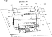
- Fig. 1 is a schematic perspective view of the printer 100 exemplified as the image forming apparatus.
- the printer 100 is described with reference to Fig. 1 .
- the image forming apparatus may be copiers and other apparatus which can form images on sheets.
- the printer 100 includes a main housing 200 which defines a room for storing various devices configured to form images on sheets (e.g. a photoconductor drum, a developing device or a container).
- the main housing 200 includes a front wall 210 perpendicular to a surface PS, onto which the printer 100 is placed; a back wall 220 opposite to the front wall 210; a left wall 230 situated between the front and back walls 210, 220; a right wall 240 opposite to the left wall 230; and a top wall 250 surrounded by the upper edges of the front, back, left and right walls 210, 220, 230, 240.
- first direction the direction from the left wall 230 to the right wall 240 is referred to as "first direction”.
- the direction from the front wall 210 to the back wall 220 is referred to as "second direction".
- the first direction is orthogonal to the second direction.
- the term “orthogonal” does not only mean an intersection at an angle of exact “90°”. An angle of intersection around "90°” is also included in the term “orthogonal” so long as the principle of the present embodiment is realized.
- the front and back walls 210, 220 are arranged along the first direction (i.e., the front and back walls 210, 220 are arranged substantially in parallel to the first direction).
- the left and right walls 230, 240 are arranged along the second direction (i.e., the left and right walls 230, 240 are arranged substantially in parallel to the second direction).
- the front wall 210 is exemplified as the first upright wall.
- the back wall 220 is exemplified as the second upright wall.
- the left wall 230 is exemplified as the side wall.
- the printer 100 further includes a sheet tray 260 onto which sheets are placed or stored.
- the sheets placed on the sheet tray 260 are sent into the main housing 200 and then subjected to image forming processes.
- the rotatable sheet tray 260 is attached to the front wall 210. A user may pull the sheet tray 260 forward to place sheets on the sheet tray 260.
- the top wall 250 of the main housing 200 includes a slope wall 251 which defines a recess for accumulating sheets after image formation processes and a discharge wall 252 standing from the slope wall 251.
- the discharge wall 252 is provided with a discharge outlet 253 from which sheets are discharged. The sheets discharged from the discharge outlet 253 are accumulated on the slope wall 251.
- the printer 100 includes multiple operation buttons 270 arranged on the front wall 210 and in an area on the top wall 250 near the front wall 210.
- a user in front of the front wall 210 may easily operate the printer 100.
- the sheet tray 260 is also provided on the front wall 210 as described above, the user standing in front of the front wall 210 may observe an amount of the sheets on the sheet tray 260. Therefore, when the user faces the front wall 210, the user may easily operate and observe operations of the printer 100.
- the front wall 210 includes a cover panel 211 detachable from the main housing 200. A user may detach the cover panel 211, which forms an upper portion of the front wall 210, in order to access various devices situated in the main housing 200.
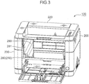
- Figs. 2 and 3 are schematic perspective views of the printer 100 from which the cover panel 211 is detached. The printer 100 is further described with reference to Figs. 1 to 3 .
- the printer 100 further includes a container 300 as a part of a developing mechanism 500 and an inner frame 280 which supports the container 300 and other devices for forming images.
- the container 300 contains developer.
- a part of the inner frame 280 nearby the cover panel 211 forms a part of the front wall 210.
- a user may detach the cover panel 211 from the main housing 200 to expose the container 300. If the container 300 contains an insufficient amount of the developer, the user may easily pull out the container 300 from the main housing 200.
- the inner frame 280 is provided with an insertion opening 281 through which the container 300 is inserted into the main housing 200.
- the user may push the container 300 containing a sufficient amount of developer along the left wall 230 through the insertion opening 281 into a storage room 290 defined by the main housing 200.
- Fig. 4 is a schematic sectional view of the printer 100. The printer 100 is further described with reference to Fig. 4 .
- the sheet tray 260 includes a lift plate 261 which lifts the leading edges of sheets.
- the printer 100 further includes a feed roller 610, which is arranged above the lift plate 261, and a friction plate 611 nearby the feed roller 610. The leading edge of a sheet lifted up by the lift plate 261 comes into contact with the feed roller 610.
- the feed roller 610 rotates so that the sheet is conveyed downstream. Sheets pass between the friction plate 611 and the feed roller 610 one by one downstream.
- the sheet tray 260 and the feeding structure configured to feed sheets from the sheet tray 260 do not by any means limit the principle of the present embodiment.
- the printer 100 further includes a pair of resist rollers 620 situated after the feed roller 610 and an image forming portion 700 which forms images on sheets.
- the feed roller 610 sends a sheet to the paired resist rollers 620.
- the paired resist rollers 620 sends the sheet to the image forming portion 700 in synchronization with image forming processes in the image forming portion 700. Consequently, an image is formed in position on the sheet.
- the image forming portion 700 includes a photoconductor drum 710 having a circumferential surface, on which an electrostatic latent image is formed; a charging device 720, which uniformly charges the circumferential surface of the photoconductor drum 710; and an exposure device 730, which irradiates the charged circumferential surface of the photoconductor drum 710 with laser light.
- a photoconductor drum 710 rotates, the circumferential surface of the photoconductor drum 710 charged by the charging device 720 moves to an exposure position at which the circumferential surface is subjected to exposure processes by the exposure device 730.
- the printer 100 is electrically connected to an external apparatus (e.g., a personal computer (not shown)) which outputs image signals.
- an external apparatus e.g., a personal computer (not shown)
- the exposure device 730 irradiates the circumferential surface of the photoconductor drum 710 with laser light in response to the image signals from the external apparatus. Consequently, a coincident electrostatic latent image to an image defined by the image signals is formed on the circumferential surface of the photoconductor drum 710.
- the photoconductor drum 710 is exemplified as the image carrier.
- the image forming portion 700 includes the aforementioned developing mechanism 500.
- the circumferential surface of the photoconductor drum 710 carrying the electrostatic latent image moves to a development position at which the circumferential surface is subjected to development processes by the developing mechanism 500.
- the developing mechanism 500 includes a developing device 400 which supplies developer to an electrostatic latent image formed on the circumferential surface of the photoconductor drum 710.
- the electrostatic latent image is developed (visualized) to form a toner image on the circumferential surface of the photoconductor drum 710.
- the structure of the developing mechanism 500 is described hereinafter.
- the image forming portion 700 further includes a transfer roller 740 which transfers a toner image formed on the circumferential surface of the photoconductor drum 710 to a sheet.
- the circumferential surface of the photoconductor drum 710 carrying the toner image moves to a transfer position at which the circumferential surface is subjected to transfer processes by the transfer roller 740.
- the aforementioned paired resist rollers 620 sends a sheet between the photoconductor drum 710 and the transfer roller 740.
- the transfer roller 740 electrostatically takes off and transfers the toner image from the photoconductor drum 710 onto a sheet surface.
- the image forming portion 700 further includes a cleaning device 750 which removes developer from the circumferential surface of the photoconductor drum 710.
- the circumferential surface of the photoconductor drum 710 after completion of toner image transfer to a sheet moves to a cleaning position at which the circumferential surface is subjected to cleaning processes by the cleaning device 750.
- the cleaning device 750 removes developer, which is remained on the circumferential surface of the photoconductor drum 710.
- the circumferential surface of the photoconductor drum 710 then moves to a charging position, at which the circumferential surface is subjected to charging processes by the charging device 720 to start the next image forming process.
- the aforementioned image forming process, and structures and arrangements of various devices used for the image forming process do not by any means limit the principle of the present embodiment.
- the printer 100 further includes a fixing device 800 configured to fix toner images on sheets.
- the fixing device 800 includes a heating roller 810, which melts toner of the toner image transferred on the sheet, and a pressure roller 820, which presses the toner image onto the heating roller.
- the photoconductor drum 710 and the transfer roller 740 send a sheet between the heating roller 810 and the pressure roller 820. Toner of the toner image carried with the sheet is melted by the heating roller 810 and then fixed on the sheet.
- the structure of the fixing device does not by any means limit the principle of the present embodiment.
- the printer 100 further includes a pair of discharge rollers 630 which is arranged nearby the discharge outlet 253 formed on the main housing 200.
- the heating roller 810 and the pressure roller 820 send a sheet to the paired discharge rollers 630.
- the paired discharge rollers 630 discharge the sheet on the slope wall 251 through the discharge outlet 253.
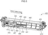
- Fig. 5 is a schematic perspective view of the developing device 400.
- the developing device 400 is described with reference to Figs. 2 , 4 and 5 .
- the developing device 400 includes a first housing 410 elongated in the first direction (i.e., the width direction of a sheet) and a developing roller 420 supported by the first housing 410. There is a feed port 411 at the left end of the first housing 410.
- the container 300 is adjacent to the left wall 230.
- the container 300 inserted along the left wall 230 is connected to the left end of the first housing 410.
- Developer stored in the container 300 is supplied into the first housing 410 through the feed port 411.
- the developing roller 420 is adjacent to the photoconductor drum 710.
- the developing roller 420 carries and supplies developer stored in the first housing 410 to an electrostatic latent image formed on the circumferential surface of the photoconductor drum 710.
- the developing roller 420 is exemplified as the carrier.
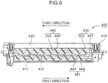
- Fig. 6 is a schematic view of an internal structure of the developing device 400. The developing device 400 is further described with reference to Fig. 6 .
- the first housing 410 of the developing device 400 includes a partition wall 412 configured to partition the storage room 430, in which developer is stored, into a first room 431 and a second room 432.
- the aforementioned feed port 411 is shown with the dotted line.
- the feed port 411 directly communicates with the first room 431.
- the first room 431 communicates with the second room 432 at the right end of the first housing 410. Developer supplied to the first room 431 through the feed port 411 is flown into the second room 432 at the right end of the first housing 410.
- the developing device 400 further includes a first conveyance screw 441 situated in the first room 431 and a second conveyance screw 442 situated in the second room 432.
- the first conveyance screw 441 includes a shaft 443 extending along the first direction and a screw 444 wound around the shaft 443.
- the second conveyance screw 442 includes a shaft 445 substantially in parallel to the shaft 443 and a screw 446 wound around the shaft 445.
- the first conveyance screw 441 When the first conveyance screw 441 rotates, developer supplied into the first room 431 is conveyed in the first direction away from the feed port 411. Consequently, the developer reaches the right end of the first housing 410 and is flown into the second room 432.
- the first conveyance screw 441 is exemplified as the first conveyance member.
- the developer flown in the second room 432 is conveyed in a third direction opposite to the first direction.
- the developer conveyed by the first and second conveyance screws 441, 442 contains toner particles and carrier particles.
- the first and second conveyance screws 441, 442 stir these particles during the conveyance. Accordingly, the toner particles are charged and electrostatically adhered to the developing roller 420 during the conveyance by the second conveyance screw 442. Therefore, the developing roller 420 uniformly carries the toner particles.
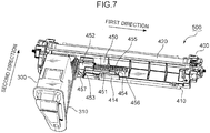
- Fig. 7 is a schematic perspective view of the developing mechanism 500.
- the developing mechanism 500 is described with reference to Figs. 2 , 4 , 5 and 7 .
- the developing mechanism 500 includes the container 300 and the developing device 400, as described above.
- the container 300 When a user pushes the container 300 into the main housing 200 along the left wall 230, the container 300 is connected to the left end of the first housing 410 of the developing device 400.
- the first housing 410 includes a substantially flat slide surface 413 which surrounds the feed port 411 opening upward.
- the container 300 includes a second housing 310 defining a storage room 311 (c.f., Fig. 4 ) in which developer is stored. When the user pushes the container 300 into the main housing 200 along the left wall 230, the container 300 slides on the slide surface 413.
- the container 300 includes a conveyance screw 320 extending in the second direction.
- the conveyance screw 320 includes a shaft 321 extending in the second direction and a screw 322 wound around the shaft 321.
- the conveyance screw 320 rotates, the developer stored in the second housing 310 is discharged towards the developing device 400.
- the developing device 400 is arranged near the back wall 220 of the main housing 200.
- the container 300 is arranged near the front wall 210 rather than the back wall 220.
- the conveyance screw 320 discharges developer in the second direction, the developer is appropriately fed from the container 300 to the developing device 400 under an intersectional structure between the container 300 and the developing device 400.
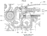
- Fig. 8 is a schematic sectional view around a connecting portion between the container 300 and the developing device 400.
- the developing mechanism 500 is further described with reference to Figs. 3 and 8 .
- the lower surface of the second housing 310 is provided with a supply port 319 from which developer is supplied to the developing device 400.
- a supply port 319 opening downward communicates with the feed port 411 opening upward. Consequently, developer conveyed by the conveyance screw 320 drops into the first room 431 by the action of gravity. The developer is then supplied to the developing roller 420 by means of the first and second conveyance screws 441, 442.
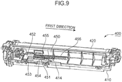
- Fig. 9 is a schematic perspective view of the developing device 400.
- Fig. 10 is a schematic perspective view of a first shutter member 451 which opens and closes the feed port 411. The opening and closing operations for the feed port 411 are described with reference to Figs. 5 , 7 , 9 and 10 .
- the developing device 400 includes a first shutter mechanism 450 which selectively opens and closes the feed port 411.
- the first shutter mechanism 450 includes the first shutter member 451.
- the first shutter member 451 is displaced between a first closing position for closing the feed port 411 and a first opening position for opening the feed port 411.
- the first shutter member 451 shown in Figs. 5 and 7 is in the first opening position.
- the first shutter member 451 shown in Fig. 9 is in the first closing position.
- the first shutter member 451 includes a substantially rectangular sliding plate 452, which slides on the slide surface 413 during the displacement between the first opening and closing positions; a substantially right triangular protruding plate 453, which protrudes towards the container 300 from the sliding plate 452 of the first shutter member 451 in the first closing position; a guide nail 454, which extends from the sliding plate 452 in the first direction; and a shaft 455, which extends in the first direction between the guide nail 454 and the developing roller 420.
- the first housing 410 includes a substantially rectangular guide plate 414 protruding upward.
- the tip of the guide nail 454 comes into contact with the guide plate 414 during displacement of the first shutter member 451 between the first opening and closing positions. Therefore, the first shutter member 451 may be stably displaced between the first opening and closing positions.
- the first shutter mechanism 450 further includes a coil spring 456 wound around the shaft 455.
- the coil spring 456 biases the first shutter member 451 towards the first closing position.
- the coil spring 456 is exemplified as the biasing member. Any other elements configured to bias the first shutter member 451 towards the first closing position may be used as the biasing member.
- Figs. 11 and 12 are schematic perspective views of the container 300.
- the container 300 is described with reference to Figs. 1 , 2 , 7 , 8 , 10 to 12 .
- the second housing 310 of the container 300 includes a main storage portion 312 having a large capacity and a protruding cylinder 313 protruding from a lower portion of the main storage portion 312 in the second direction.
- a user may detach the cover panel 211 to expose the main storage portion 312 (c.f., Figs. 1 and 2 ). Therefore, the user may easily attach and detach the container 300 to and from the developing device 400.
- a large part of developer is stored in the main storage portion 312.
- the conveyance screw 320 is inserted into the protruding cylinder 313.
- the developer is conveyed from the main storage portion 312 to the protruding cylinder 313 as rotation of the conveyance screw 320 and the action of gravity.
- the developer conveyed by the conveyance screw 320 in the second direction is then discharged through the supply port 319 and supplied to the developing device 400 through the feed port 411.
- the conveyance screw 320 is exemplified as the second conveyance member.
- the container 300 further includes a second shutter mechanism 330 which selectively opens and closes the supply port 319 provided at the lower surface of the protruding cylinder 313.
- the second shutter mechanism 330 is provided at the tip of the protruding cylinder 313.
- the second housing 310 includes a substantially triangular protruding tongue 314 which protrudes in the second direction.
- the protruding tongue 314 hits the developing device 400 at first.
- the protruding plate 453 of the first shutter member 451 includes a sloped first contact edge 457.
- the protruding tongue 314 includes a sloped second contact edge 315.
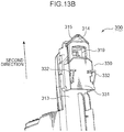
- Figs. 13A and 13B are schematic bottom perspective views of the container 300.
- the second shutter mechanism 330 is described with reference to Figs. 13A and 13B .
- the second shutter mechanism 330 includes a slidable second shutter member 331, which is attached to the protruding cylinder 313 of the second housing 310, and a pair of first protrusions 332, which protrudes from the lower surface of the second shutter member 331.
- the second shutter member 331 is displaced along the protruding cylinder 313, which protrudes in the second direction, between a second closing position for closing the supply port 319 and a second opening position for opening the supply port 319.
- the second shutter member 331 in Fig. 13A is in the second closing position.
- the second shutter member 331 shown in Fig. 13B is in the second opening position.
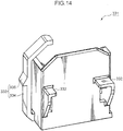
- Fig. 14 is a schematic perspective view of the second shutter member 331.
- the second shutter mechanism 330 is further described with reference to Figs. 5 and 13A to 14 .
- the slide surface 413 includes a facing edge 415, which faces the first protrusion 332.
- the second shutter member 331 is arranged at the second closing position.
- the first protrusion 332 hits the facing edge 415.
- the second shutter member 331 is displaced to the second opening position. Consequently, the supply port 319 communicates with the feed port 411.
- the facing edge 415 is exemplified as the edge.
- the second contact edge 315 of the protruding tongue 314 hits the first contact edge 457 of the first shutter member 451 at first. Consequently, the first shutter member 451 is displaced to the first opening position.
- the second shutter member 331 slides on the slide surface 413.
- the first protrusion 332 protruding downward from the second shutter member 331 hits the facing edge 415, and thereafter the second shutter member 331 is displaced to the second opening position. Therefore, the feed port 411 is opened earlier than the supply port 319. Accordingly, there is little leakage of developer in the container 300 outside the developing device 400.
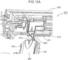
- Figs. 15A to 15C are perspective views schematically showing connection processes of the container 300 with the developing device 400.
- the connection processes of the developing device 400 with the container 300 are described with reference to Figs. 5 and 14 to 15C .
- the first shutter member 451 is in the first closing position.
- the second shutter member 331 is in the second closing position.
- the tip of the protruding tongue 314 of the second housing 310 is in contact with the tip of the protruding plate 453 of the first shutter member 451.
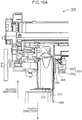
- Fig. 16A is a schematic plan view corresponding to Fig. 15B .
- Fig. 16B is a schematic plan view corresponding to Fig. 15C .
- the connection processes are further described with reference to Figs. 3 , 14 , 16A and 16B .
- the second shutter mechanism 330 further includes a second protrusion 333 protruding rightward from the second shutter member 331.
- the second protrusion 333 includes an arm 334 in a substantially J-shape and a projection 335 projecting rightward from the arm 334.
- the tip of the arm 334 is situated in front of the protruding cylinder 313 of the second housing 310 in the second direction.
- the second shutter member 331 moves backward with respect to the tip of the protruding cylinder 313 in the second direction when the second shutter member 331 is displaced to the second opening position. Consequently, as shown in Fig. 16B , the tip of the arm 334 hits the right surface of the protruding cylinder 313, and then is bent rightward as a whole.
- the developing mechanism 500 further includes a fixed wall 295 situated on the right side of the protruding cylinder 313.
- the fixed wall 295 may be a part fixed in the storage room 290, which is defined by the main housing 200.
- the fixed wall 295 is fixed to the main housing 200 in the storage room 290.
- the fixed wall 295 is used as the fixed portion.
- the second protrusion 333 is situated between the fixed wall 295 and the protruding cylinder 313.
- the arm 334 is bent rightward due to the displacement of the second shutter member 331 to the second opening position, as shown in Fig. 16B , the projection 335 engages with an edge of the fixed wall 295.
- the second shutter member 331 is displaced from the second opening position to the second closing position by the projection 335 engaged with the fixed wall 295. Therefore, there is little leakage of developer during the detachment of the container 300 from the developing device 400.
Landscapes
- Physics & Mathematics (AREA)
- General Physics & Mathematics (AREA)
- Dry Development In Electrophotography (AREA)
Claims (11)
- Entwicklungsmechanismus (500) für die Entwicklung mit Entwickler in einem Hauptgehäuse (200), wobei der Entwicklungsmechanismus (500) umfasst:eine Entwicklungsvorrichtung (400), die konfiguriert ist, um den Entwickler an ein elektrostatisches latentes Bild zuzuführen und das elektrostatische latente Bild zu entwickeln; undeinen Behälter (300), der aufgebaut ist, um den Entwickler zu enthalten und in das Hauptgehäuse (200) eingesetzt zu werden, wobeidie Entwicklungsvorrichtung (400) umfasst:einen Träger (420), der aufgebaut ist, um den Entwickler aufzunehmen und ihn an das elektrostatische latente Bild zuzuführen;ein erstes Gehäuse (410), das mit einer Speisungsöffnung (411) versehen ist, durch welche der Entwickler zugeführt wird und das einen Rand (415) umfasst, der dem Behälter (300) zugewandt ist;ein erstes Förderelement (441), das aufgebaut ist, um den Entwickler entlang einer ersten Richtung weg von der Speisungsöffnung (411) zu befördern; undeinen ersten Verschlussmechanismus (450), der ein erstes Verschlusselement (451) umfasst, das aufgebaut ist, um sich selektiv zwischen einer ersten Schließposition zum Schließen der Speisungsöffnung (411) und einer ersten Öffnungsposition zum Öffnen der Speisungsöffnung (411) zu verschieben; undder Behälter (300) umfasst:ein zweites Gehäuse (310), das mit einer Versorgungsöffnung (319) zum Zuführen des Entwicklers durch die Speisungsöffnung (411) an die Entwicklungsvorrichtung (400) versehen ist;einen zweiten Verschlussmechanismus (330), der aufgebaut ist, um die Versorgungsöffnung (319) selektiv zu öffnen und zu schließen; undein zweites Förderelement (320), das aufgebaut ist, um den Entwickler entlang einer zweiten Richtung quer zu der ersten Richtung zu fördern und den Entwickler durch die Versorgungsöffnung (319) abzugeben,der zweite Verschlussmechanismus(330) umfasst: ein zweites Verschlusselement (331), das zwischen einer zweiten Schließposition zum Schließen der Versorgungsöffnung (319) und einer zweiten Öffnungsposition zum Öffnen der Versorgungsöffnung (319) verschoben wird, und einen ersten Vorsprung (332), der von dem zweiten Verschlusselement (331) vorsteht, unddas zweite Gehäuse (310) eine im Wesentlichen dreieckige vorstehende Zunge (314) umfasst, die in der zweiten Richtung vorsteht, um auf das erste Verschlusselement (451) zu treffen und es zu der ersten Öffnungsposition zu verschieben, bevor der erste Vorsprung (332) die Kante (415) trifft,das erste Verschlusselement (451) umfasst:eine Gleitplatte (452), die während der Verschiebung zwischen den ersten Öffnungs- und Schließpositionen auf dem ersten Gehäuse (410) gleitet; undeine im Wesentlichen dreieckige vorstehende Platte (453), die von der Gleitplatte (452) in Richtung des Behälters (300) vorsteht,wobei die vorstehende Platte einen geneigten ersten Kontaktrand (457) umfasst,wobei die vorstehende Zunge (314) einen geneigten zweiten Kontaktrand (315) umfasst, undwenn der Behälter (300) an der Entwicklungsvorrichtung (400) angebracht wird, der zweite Kontaktrand (315) auf den ersten Kontaktrand trifft, wobei das erste Verschlusselement (451) zu der ersten Öffnungsposition verschoben wird, indem der zweite Kontaktrand auf den ersten Kontaktrand (457) trifft, um das erste Verschlusselement (451) in die erste Richtung zu bewegen, und dann der erste Vorsprung (332) auf den Rand (415) trifft, wobei das zweite Verschlusselement (331) von der zweiten Schließposition zu der zweiten Öffnungsposition verschoben wird, indem der erste Vorsprung (332) auf den Rand trifft, um das zweite Verschlusselement (331) in eine Richtung entgegengesetzt zu der zweiten Richtung zu bewegen, so dass das zweite Verschlusselement (331) die Versorgungsöffnung (319) mit der Speisungsöffnung (411) in Verbindung bringt.
- Entwicklungsmechanismus (500) nach Anspruch 1, wobei:der erste Verschlussmechanismus (450) umfasst:ein Vorspannelement (456), das aufgebaut ist, um das erste Verschlusselement (451) in Richtung der ersten Schließposition vorzuspannen.
- Entwicklungsmechanismus (500) nach Anspruch 2, wobei:der Behälter (300) von der Entwicklungsvorrichtung (400) abnehmbar ist.
- Entwicklungsmechanismus (500) nach Anspruch 3, wobei:die Speisungsöffnung (411) sich nach oben öffnet,die Versorgungsöffnung (319) sich nach unten öffnet, unddie Speisungsöffnung (411) mit der Versorgungsöffnung (319) in Verbindung steht, wenn das erste Verschlusselement (451) sich zu der ersten Öffnungsposition bewegt, während das zweite Verschlusselement (331) sich auch zu der zweiten Öffnungsposition bewegt.
- Entwicklungsmechanismus (500) nach Anspruch 4, wobei:das erste Gehäuse (410) eine Gleitfläche (413), die die Speisungsöffnung (411) umgibt, umfasst, wobei das zweite Verschlusselement (331) auf der Gleitfläche (413) gleitet,die Gleitfläche (413) den Rand (415) umfasst, undder erste Vorsprung (332) nach unten vorsteht.
- Entwicklungsmechanismus (500) nach Anspruch 5, der ferner umfasst: einen festen Abschnitt (295), der neben dem zweiten Verschlusselement (331) an dem Hauptgehäuse (200) befestigt ist, wobei:der zweite Verschlussmechanismus (330) einen zweiten Vorsprung (333) umfasst, der seitlich von dem zweiten Verschlusselement (331) vorsteht,der zweite Vorsprung (333) mit dem festen Abschnitt (295) in Eingriff ist, während das zweite Verschlusselement (331) in der zweiten Öffnungsposition ist, undder feste Abschnitt (295) das zweite Verschlusselement (331) von der zweiten Öffnungsposition zu der zweiten Schließposition bewegt, wenn der Behälter von der Entwicklungsvorrichtung (400) abgenommen wird.
- Entwicklungsmechanismus (500) nach einem der Ansprüche 1 bis 6, wobei die erste Richtung orthogonal zu der zweiten Richtung ist.
- Bilderzeugungsvorrichtung (100) zum Erzeugen eines Bilds, die umfasst:den Entwicklungsmechanismus (500) nach einem der Ansprüche 1 bis 7; undeinen Bildträger (710), auf dem das elektrostatische latente Bild erzeugt wird.
- Bilderzeugungsvorrichtung (100) nach Anspruch 8, die umfasst:den Entwicklungsmechanismus (500) nach Anspruch 6, wobeidas Hauptgehäuse (200) einen Lagerraum (290) für die Lagerung des Bildträgers (710) und des Entwicklungsmechanismus (500) definiert.
- Bilderzeugungsvorrichtung (100) nach Anspruch 9, wobei
das Hauptgehäuse (200) eine erste aufrechte Wand (210) entlang der ersten Richtung und eine zweite aufrechte Wand (220) gegenüber der ersten aufrechten Wand (210) umfasst,
die erste aufrechte Wand (210) mit einer Einsatzöffnung (281) versehen ist, durch welche der Behälter (300) in das Hauptgehäuse (200) eingesetzt wird,
die zweite aufrechte Wand (200) näher an der Entwicklungsvorrichtung (400) als die erste aufrechte Wand (210) ist, und
der Behälter (300) von der Einsatzöffnung (281) in den Lagerraum (290) in Richtung der zweiten aufrechten Wand (220) eingesetzt und dann mit der Entwicklungsvorrichtung (400) verbunden wird. - Bilderzeugungsvorrichtung (100) nach Anspruch 10, wobei:das Hauptgehäuse (200) eine Seitenwand (230) umfasst, die zwischen den ersten und zweiten aufrechten Wänden (210, 220) angeordnet ist,die Seitenwand (230) sich entlang der zweiten Richtung erstreckt, undder Behälter (300) entlang der Seitenwand (230) in den Lagerraum (290) eingesetzt wird.
Applications Claiming Priority (1)
| Application Number | Priority Date | Filing Date | Title |
|---|---|---|---|
| JP2011258129A JP5514792B2 (ja) | 2011-11-25 | 2011-11-25 | 現像機構及び画像形成装置 |
Publications (3)
| Publication Number | Publication Date |
|---|---|
| EP2597528A2 EP2597528A2 (de) | 2013-05-29 |
| EP2597528A3 EP2597528A3 (de) | 2013-08-07 |
| EP2597528B1 true EP2597528B1 (de) | 2017-03-15 |
Family
ID=47216024
Family Applications (1)
| Application Number | Title | Priority Date | Filing Date |
|---|---|---|---|
| EP12007775.5A Not-in-force EP2597528B1 (de) | 2011-11-25 | 2012-11-16 | Entwicklungsmechanismus und Bilderzeugungsvorrichtung |
Country Status (5)
| Country | Link |
|---|---|
| US (1) | US8811862B2 (de) |
| EP (1) | EP2597528B1 (de) |
| JP (1) | JP5514792B2 (de) |
| KR (1) | KR101451707B1 (de) |
| CN (1) | CN103135400B (de) |
Families Citing this family (4)
| Publication number | Priority date | Publication date | Assignee | Title |
|---|---|---|---|---|
| JP5086460B2 (ja) * | 2011-04-15 | 2012-11-28 | 京セラドキュメントソリューションズ株式会社 | 画像形成装置 |
| JP5775836B2 (ja) * | 2012-02-24 | 2015-09-09 | 京セラドキュメントソリューションズ株式会社 | 画像形成装置 |
| KR101589504B1 (ko) | 2014-06-03 | 2016-01-28 | 삼성전자주식회사 | 전자사진방식 화상형성장치 |
| JP6380324B2 (ja) | 2015-10-02 | 2018-08-29 | 京セラドキュメントソリューションズ株式会社 | トナー容器及び画像形成装置 |
Citations (1)
| Publication number | Priority date | Publication date | Assignee | Title |
|---|---|---|---|---|
| JP2009210966A (ja) * | 2008-03-06 | 2009-09-17 | Murata Mach Ltd | 画像形成装置 |
Family Cites Families (28)
| Publication number | Priority date | Publication date | Assignee | Title |
|---|---|---|---|---|
| JPS62200386A (ja) | 1986-02-28 | 1987-09-04 | Konishiroku Photo Ind Co Ltd | 現像剤回収容器を備えた記録装置 |
| JP3187584B2 (ja) | 1993-01-11 | 2001-07-11 | 京セラミタ株式会社 | 開口シャッタ開閉機構 |
| EP0866380B1 (de) | 1993-01-26 | 2001-06-06 | Sharp Kabushiki Kaisha | Bilderzeugungsgerät |
| JP2986660B2 (ja) * | 1993-09-30 | 1999-12-06 | シャープ株式会社 | 電子写真装置 |
| JP2785096B2 (ja) * | 1993-04-02 | 1998-08-13 | 三田工業株式会社 | 画像生成装置における現像装置 |
| JP2864951B2 (ja) | 1993-08-05 | 1999-03-08 | 株式会社日立製作所 | 現像装置 |
| JP3178779B2 (ja) * | 1995-07-31 | 2001-06-25 | 京セラミタ株式会社 | トナーカートリッジ |
| JP3267879B2 (ja) * | 1996-11-13 | 2002-03-25 | 京セラミタ株式会社 | トナー補給装置およびトナーカートリッジ |
| US5862441A (en) | 1996-12-27 | 1999-01-19 | Mita Industrial Co., Ltd. | Image-forming machine |
| JP3341107B2 (ja) * | 1996-12-27 | 2002-11-05 | 京セラミタ株式会社 | 画像形成機 |
| JP3321728B2 (ja) | 1997-11-06 | 2002-09-09 | 京セラミタ株式会社 | 画像形成機のトナー補給装置およびこれに用いるトナーカートリッジ |
| JP3170754B2 (ja) * | 1998-08-06 | 2001-05-28 | 京セラミタ株式会社 | 画像形成機のトナー補給装置 |
| JP3498005B2 (ja) * | 1999-04-30 | 2004-02-16 | シャープ株式会社 | トナー補給装置 |
| JP2001154473A (ja) * | 1999-11-24 | 2001-06-08 | Konica Corp | 画像形成装置 |
| KR100362390B1 (ko) * | 2000-12-29 | 2002-11-23 | 삼성전자 주식회사 | 화상형성장치의 현상기-토너 카트리지 조립체 |
| JP2004184746A (ja) * | 2002-12-04 | 2004-07-02 | Kyocera Mita Corp | 現像装置 |
| JP3705364B2 (ja) * | 2003-05-06 | 2005-10-12 | 富士ゼロックス株式会社 | 画像形成装置及びこれに用いられるプロセスカートリッジ、現像装置 |
| JP4109177B2 (ja) * | 2003-09-30 | 2008-07-02 | 京セラミタ株式会社 | トナー供給装置およびシャッタ構造 |
| JP4635645B2 (ja) * | 2005-02-28 | 2011-02-23 | ブラザー工業株式会社 | 画像形成装置及びトナーカートリッジ |
| EP1767999B1 (de) | 2005-09-21 | 2012-03-21 | Brother Kogyo Kabushiki Kaisha | Tonerkassette für Entwicklungseinheit |
| JP4665686B2 (ja) * | 2005-09-21 | 2011-04-06 | ブラザー工業株式会社 | 現像装置 |
| JP4792924B2 (ja) * | 2005-11-07 | 2011-10-12 | コニカミノルタビジネステクノロジーズ株式会社 | カラー画像形成装置 |
| JP4802845B2 (ja) * | 2006-04-25 | 2011-10-26 | 村田機械株式会社 | 画像形成装置 |
| JP4386053B2 (ja) * | 2006-07-04 | 2009-12-16 | セイコーエプソン株式会社 | 画像形成装置 |
| JP4293214B2 (ja) * | 2006-09-12 | 2009-07-08 | 村田機械株式会社 | 画像形成装置 |
| JP4980731B2 (ja) | 2007-01-15 | 2012-07-18 | 京セラドキュメントソリューションズ株式会社 | トナーコンテナ |
| KR101347158B1 (ko) | 2007-01-29 | 2014-01-03 | 삼성전자주식회사 | 유로 개폐장치를 구비한 화상형성장치 |
| TW201027285A (en) | 2009-01-10 | 2010-07-16 | Gen Plastic Ind Co Ltd | Switching device of toner cartridge |
-
2011
- 2011-11-25 JP JP2011258129A patent/JP5514792B2/ja active Active
-
2012
- 2012-11-13 CN CN201210452263.7A patent/CN103135400B/zh not_active Expired - Fee Related
- 2012-11-13 KR KR1020120127907A patent/KR101451707B1/ko active Active
- 2012-11-15 US US13/677,368 patent/US8811862B2/en active Active
- 2012-11-16 EP EP12007775.5A patent/EP2597528B1/de not_active Not-in-force
Patent Citations (1)
| Publication number | Priority date | Publication date | Assignee | Title |
|---|---|---|---|---|
| JP2009210966A (ja) * | 2008-03-06 | 2009-09-17 | Murata Mach Ltd | 画像形成装置 |
Also Published As
| Publication number | Publication date |
|---|---|
| CN103135400B (zh) | 2015-08-19 |
| KR20130058609A (ko) | 2013-06-04 |
| US20130136503A1 (en) | 2013-05-30 |
| JP2013113928A (ja) | 2013-06-10 |
| US8811862B2 (en) | 2014-08-19 |
| JP5514792B2 (ja) | 2014-06-04 |
| EP2597528A3 (de) | 2013-08-07 |
| EP2597528A2 (de) | 2013-05-29 |
| CN103135400A (zh) | 2013-06-05 |
| KR101451707B1 (ko) | 2014-10-16 |
Similar Documents
| Publication | Publication Date | Title |
|---|---|---|
| US8335455B2 (en) | Toner supplying device and image forming apparatus | |
| EP2597533B1 (de) | Bilderzeugungsmechanismus mit Mechanismus zur Einschränkung des Entfernens einer Entwicklungsvorrichtung | |
| TWI430054B (zh) | 影像形成劑儲存容器,影像形成裝置,影像形成劑儲存容器之安裝方法及影像形成劑儲存容器之移除方法 | |
| EP2597528B1 (de) | Entwicklungsmechanismus und Bilderzeugungsvorrichtung | |
| US8787796B2 (en) | Developing unit and image forming apparatus including the same | |
| JP2017068211A (ja) | トナー容器及び画像形成装置 | |
| JP2014228830A (ja) | 現像剤容器、現像装置、現像剤補給装置、プロセスカートリッジ、画像形成装置 | |
| EP2653931B1 (de) | Entwicklungsvorrichtung und Bilderzeugungsvorrichtung | |
| CN102314126B (zh) | 显影剂容器和使用该显影剂容器的图像形成装置 | |
| JP5775836B2 (ja) | 画像形成装置 | |
| US10935906B2 (en) | Developer supply device and image forming apparatus incorporating same | |
| CN100593760C (zh) | 图像形成装置 | |
| US10877428B2 (en) | Developing device and image forming apparatus | |
| JP2014157244A (ja) | 画像形成装置 | |
| CN112558445A (zh) | 粉体容器的安装装置、图像形成装置及粉体容器 | |
| JP2008139636A (ja) | 画像形成装置 | |
| JP6783522B2 (ja) | 画像形成装置 | |
| JP2013003245A (ja) | 画像形成装置 |
Legal Events
| Date | Code | Title | Description |
|---|---|---|---|
| PUAI | Public reference made under article 153(3) epc to a published international application that has entered the european phase |
Free format text: ORIGINAL CODE: 0009012 |
|
| AK | Designated contracting states |
Kind code of ref document: A2 Designated state(s): AL AT BE BG CH CY CZ DE DK EE ES FI FR GB GR HR HU IE IS IT LI LT LU LV MC MK MT NL NO PL PT RO RS SE SI SK SM TR |
|
| AX | Request for extension of the european patent |
Extension state: BA ME |
|
| PUAL | Search report despatched |
Free format text: ORIGINAL CODE: 0009013 |
|
| AK | Designated contracting states |
Kind code of ref document: A3 Designated state(s): AL AT BE BG CH CY CZ DE DK EE ES FI FR GB GR HR HU IE IS IT LI LT LU LV MC MK MT NL NO PL PT RO RS SE SI SK SM TR |
|
| AX | Request for extension of the european patent |
Extension state: BA ME |
|
| RIC1 | Information provided on ipc code assigned before grant |
Ipc: G03G 21/16 20060101ALI20130704BHEP Ipc: G03G 15/08 20060101AFI20130704BHEP |
|
| 17P | Request for examination filed |
Effective date: 20140130 |
|
| RBV | Designated contracting states (corrected) |
Designated state(s): AL AT BE BG CH CY CZ DE DK EE ES FI FR GB GR HR HU IE IS IT LI LT LU LV MC MK MT NL NO PL PT RO RS SE SI SK SM TR |
|
| 17Q | First examination report despatched |
Effective date: 20160701 |
|
| GRAP | Despatch of communication of intention to grant a patent |
Free format text: ORIGINAL CODE: EPIDOSNIGR1 |
|
| INTG | Intention to grant announced |
Effective date: 20161202 |
|
| RAP1 | Party data changed (applicant data changed or rights of an application transferred) |
Owner name: KYOCERA DOCUMENT SOLUTIONS INC. |
|
| GRAS | Grant fee paid |
Free format text: ORIGINAL CODE: EPIDOSNIGR3 |
|
| GRAA | (expected) grant |
Free format text: ORIGINAL CODE: 0009210 |
|
| AK | Designated contracting states |
Kind code of ref document: B1 Designated state(s): AL AT BE BG CH CY CZ DE DK EE ES FI FR GB GR HR HU IE IS IT LI LT LU LV MC MK MT NL NO PL PT RO RS SE SI SK SM TR |
|
| REG | Reference to a national code |
Ref country code: CH Ref legal event code: EP Ref country code: GB Ref legal event code: FG4D |
|
| REG | Reference to a national code |
Ref country code: IE Ref legal event code: FG4D |
|
| REG | Reference to a national code |
Ref country code: AT Ref legal event code: REF Ref document number: 876180 Country of ref document: AT Kind code of ref document: T Effective date: 20170415 |
|
| REG | Reference to a national code |
Ref country code: DE Ref legal event code: R096 Ref document number: 602012029738 Country of ref document: DE |
|
| REG | Reference to a national code |
Ref country code: NL Ref legal event code: MP Effective date: 20170315 |
|
| REG | Reference to a national code |
Ref country code: LT Ref legal event code: MG4D |
|
| PG25 | Lapsed in a contracting state [announced via postgrant information from national office to epo] |
Ref country code: LT Free format text: LAPSE BECAUSE OF FAILURE TO SUBMIT A TRANSLATION OF THE DESCRIPTION OR TO PAY THE FEE WITHIN THE PRESCRIBED TIME-LIMIT Effective date: 20170315 Ref country code: GR Free format text: LAPSE BECAUSE OF FAILURE TO SUBMIT A TRANSLATION OF THE DESCRIPTION OR TO PAY THE FEE WITHIN THE PRESCRIBED TIME-LIMIT Effective date: 20170616 Ref country code: NO Free format text: LAPSE BECAUSE OF FAILURE TO SUBMIT A TRANSLATION OF THE DESCRIPTION OR TO PAY THE FEE WITHIN THE PRESCRIBED TIME-LIMIT Effective date: 20170615 Ref country code: FI Free format text: LAPSE BECAUSE OF FAILURE TO SUBMIT A TRANSLATION OF THE DESCRIPTION OR TO PAY THE FEE WITHIN THE PRESCRIBED TIME-LIMIT Effective date: 20170315 Ref country code: HR Free format text: LAPSE BECAUSE OF FAILURE TO SUBMIT A TRANSLATION OF THE DESCRIPTION OR TO PAY THE FEE WITHIN THE PRESCRIBED TIME-LIMIT Effective date: 20170315 |
|
| REG | Reference to a national code |
Ref country code: AT Ref legal event code: MK05 Ref document number: 876180 Country of ref document: AT Kind code of ref document: T Effective date: 20170315 |
|
| PG25 | Lapsed in a contracting state [announced via postgrant information from national office to epo] |
Ref country code: RS Free format text: LAPSE BECAUSE OF FAILURE TO SUBMIT A TRANSLATION OF THE DESCRIPTION OR TO PAY THE FEE WITHIN THE PRESCRIBED TIME-LIMIT Effective date: 20170315 Ref country code: BG Free format text: LAPSE BECAUSE OF FAILURE TO SUBMIT A TRANSLATION OF THE DESCRIPTION OR TO PAY THE FEE WITHIN THE PRESCRIBED TIME-LIMIT Effective date: 20170615 Ref country code: LV Free format text: LAPSE BECAUSE OF FAILURE TO SUBMIT A TRANSLATION OF THE DESCRIPTION OR TO PAY THE FEE WITHIN THE PRESCRIBED TIME-LIMIT Effective date: 20170315 Ref country code: SE Free format text: LAPSE BECAUSE OF FAILURE TO SUBMIT A TRANSLATION OF THE DESCRIPTION OR TO PAY THE FEE WITHIN THE PRESCRIBED TIME-LIMIT Effective date: 20170315 |
|
| PG25 | Lapsed in a contracting state [announced via postgrant information from national office to epo] |
Ref country code: NL Free format text: LAPSE BECAUSE OF FAILURE TO SUBMIT A TRANSLATION OF THE DESCRIPTION OR TO PAY THE FEE WITHIN THE PRESCRIBED TIME-LIMIT Effective date: 20170315 |
|
| REG | Reference to a national code |
Ref country code: FR Ref legal event code: PLFP Year of fee payment: 6 |
|
| PG25 | Lapsed in a contracting state [announced via postgrant information from national office to epo] |
Ref country code: CZ Free format text: LAPSE BECAUSE OF FAILURE TO SUBMIT A TRANSLATION OF THE DESCRIPTION OR TO PAY THE FEE WITHIN THE PRESCRIBED TIME-LIMIT Effective date: 20170315 Ref country code: RO Free format text: LAPSE BECAUSE OF FAILURE TO SUBMIT A TRANSLATION OF THE DESCRIPTION OR TO PAY THE FEE WITHIN THE PRESCRIBED TIME-LIMIT Effective date: 20170315 Ref country code: EE Free format text: LAPSE BECAUSE OF FAILURE TO SUBMIT A TRANSLATION OF THE DESCRIPTION OR TO PAY THE FEE WITHIN THE PRESCRIBED TIME-LIMIT Effective date: 20170315 Ref country code: AT Free format text: LAPSE BECAUSE OF FAILURE TO SUBMIT A TRANSLATION OF THE DESCRIPTION OR TO PAY THE FEE WITHIN THE PRESCRIBED TIME-LIMIT Effective date: 20170315 Ref country code: ES Free format text: LAPSE BECAUSE OF FAILURE TO SUBMIT A TRANSLATION OF THE DESCRIPTION OR TO PAY THE FEE WITHIN THE PRESCRIBED TIME-LIMIT Effective date: 20170315 Ref country code: SK Free format text: LAPSE BECAUSE OF FAILURE TO SUBMIT A TRANSLATION OF THE DESCRIPTION OR TO PAY THE FEE WITHIN THE PRESCRIBED TIME-LIMIT Effective date: 20170315 Ref country code: IT Free format text: LAPSE BECAUSE OF FAILURE TO SUBMIT A TRANSLATION OF THE DESCRIPTION OR TO PAY THE FEE WITHIN THE PRESCRIBED TIME-LIMIT Effective date: 20170315 |
|
| PG25 | Lapsed in a contracting state [announced via postgrant information from national office to epo] |
Ref country code: SM Free format text: LAPSE BECAUSE OF FAILURE TO SUBMIT A TRANSLATION OF THE DESCRIPTION OR TO PAY THE FEE WITHIN THE PRESCRIBED TIME-LIMIT Effective date: 20170315 Ref country code: IS Free format text: LAPSE BECAUSE OF FAILURE TO SUBMIT A TRANSLATION OF THE DESCRIPTION OR TO PAY THE FEE WITHIN THE PRESCRIBED TIME-LIMIT Effective date: 20170715 Ref country code: PL Free format text: LAPSE BECAUSE OF FAILURE TO SUBMIT A TRANSLATION OF THE DESCRIPTION OR TO PAY THE FEE WITHIN THE PRESCRIBED TIME-LIMIT Effective date: 20170315 Ref country code: PT Free format text: LAPSE BECAUSE OF FAILURE TO SUBMIT A TRANSLATION OF THE DESCRIPTION OR TO PAY THE FEE WITHIN THE PRESCRIBED TIME-LIMIT Effective date: 20170717 |
|
| REG | Reference to a national code |
Ref country code: DE Ref legal event code: R097 Ref document number: 602012029738 Country of ref document: DE |
|
| PLBE | No opposition filed within time limit |
Free format text: ORIGINAL CODE: 0009261 |
|
| STAA | Information on the status of an ep patent application or granted ep patent |
Free format text: STATUS: NO OPPOSITION FILED WITHIN TIME LIMIT |
|
| PG25 | Lapsed in a contracting state [announced via postgrant information from national office to epo] |
Ref country code: DK Free format text: LAPSE BECAUSE OF FAILURE TO SUBMIT A TRANSLATION OF THE DESCRIPTION OR TO PAY THE FEE WITHIN THE PRESCRIBED TIME-LIMIT Effective date: 20170315 |
|
| 26N | No opposition filed |
Effective date: 20171218 |
|
| PG25 | Lapsed in a contracting state [announced via postgrant information from national office to epo] |
Ref country code: SI Free format text: LAPSE BECAUSE OF FAILURE TO SUBMIT A TRANSLATION OF THE DESCRIPTION OR TO PAY THE FEE WITHIN THE PRESCRIBED TIME-LIMIT Effective date: 20170315 |
|
| PG25 | Lapsed in a contracting state [announced via postgrant information from national office to epo] |
Ref country code: MC Free format text: LAPSE BECAUSE OF FAILURE TO SUBMIT A TRANSLATION OF THE DESCRIPTION OR TO PAY THE FEE WITHIN THE PRESCRIBED TIME-LIMIT Effective date: 20170315 |
|
| PG25 | Lapsed in a contracting state [announced via postgrant information from national office to epo] |
Ref country code: LI Free format text: LAPSE BECAUSE OF NON-PAYMENT OF DUE FEES Effective date: 20171130 Ref country code: CH Free format text: LAPSE BECAUSE OF NON-PAYMENT OF DUE FEES Effective date: 20171130 |
|
| PG25 | Lapsed in a contracting state [announced via postgrant information from national office to epo] |
Ref country code: LU Free format text: LAPSE BECAUSE OF NON-PAYMENT OF DUE FEES Effective date: 20171116 |
|
| REG | Reference to a national code |
Ref country code: BE Ref legal event code: MM Effective date: 20171130 |
|
| REG | Reference to a national code |
Ref country code: IE Ref legal event code: MM4A |
|
| PG25 | Lapsed in a contracting state [announced via postgrant information from national office to epo] |
Ref country code: MT Free format text: LAPSE BECAUSE OF NON-PAYMENT OF DUE FEES Effective date: 20171116 |
|
| REG | Reference to a national code |
Ref country code: FR Ref legal event code: PLFP Year of fee payment: 7 |
|
| PG25 | Lapsed in a contracting state [announced via postgrant information from national office to epo] |
Ref country code: IE Free format text: LAPSE BECAUSE OF NON-PAYMENT OF DUE FEES Effective date: 20171116 |
|
| PG25 | Lapsed in a contracting state [announced via postgrant information from national office to epo] |
Ref country code: BE Free format text: LAPSE BECAUSE OF NON-PAYMENT OF DUE FEES Effective date: 20171130 |
|
| PG25 | Lapsed in a contracting state [announced via postgrant information from national office to epo] |
Ref country code: HU Free format text: LAPSE BECAUSE OF FAILURE TO SUBMIT A TRANSLATION OF THE DESCRIPTION OR TO PAY THE FEE WITHIN THE PRESCRIBED TIME-LIMIT; INVALID AB INITIO Effective date: 20121116 |
|
| PG25 | Lapsed in a contracting state [announced via postgrant information from national office to epo] |
Ref country code: CY Free format text: LAPSE BECAUSE OF NON-PAYMENT OF DUE FEES Effective date: 20170315 |
|
| PG25 | Lapsed in a contracting state [announced via postgrant information from national office to epo] |
Ref country code: MK Free format text: LAPSE BECAUSE OF FAILURE TO SUBMIT A TRANSLATION OF THE DESCRIPTION OR TO PAY THE FEE WITHIN THE PRESCRIBED TIME-LIMIT Effective date: 20170315 |
|
| PG25 | Lapsed in a contracting state [announced via postgrant information from national office to epo] |
Ref country code: TR Free format text: LAPSE BECAUSE OF FAILURE TO SUBMIT A TRANSLATION OF THE DESCRIPTION OR TO PAY THE FEE WITHIN THE PRESCRIBED TIME-LIMIT Effective date: 20170315 |
|
| PG25 | Lapsed in a contracting state [announced via postgrant information from national office to epo] |
Ref country code: AL Free format text: LAPSE BECAUSE OF FAILURE TO SUBMIT A TRANSLATION OF THE DESCRIPTION OR TO PAY THE FEE WITHIN THE PRESCRIBED TIME-LIMIT Effective date: 20170315 |
|
| PGFP | Annual fee paid to national office [announced via postgrant information from national office to epo] |
Ref country code: GB Payment date: 20201104 Year of fee payment: 9 Ref country code: FR Payment date: 20201013 Year of fee payment: 9 Ref country code: DE Payment date: 20201103 Year of fee payment: 9 |
|
| REG | Reference to a national code |
Ref country code: DE Ref legal event code: R119 Ref document number: 602012029738 Country of ref document: DE |
|
| GBPC | Gb: european patent ceased through non-payment of renewal fee |
Effective date: 20211116 |
|
| PG25 | Lapsed in a contracting state [announced via postgrant information from national office to epo] |
Ref country code: GB Free format text: LAPSE BECAUSE OF NON-PAYMENT OF DUE FEES Effective date: 20211116 Ref country code: DE Free format text: LAPSE BECAUSE OF NON-PAYMENT OF DUE FEES Effective date: 20220601 |
|
| PG25 | Lapsed in a contracting state [announced via postgrant information from national office to epo] |
Ref country code: FR Free format text: LAPSE BECAUSE OF NON-PAYMENT OF DUE FEES Effective date: 20211130 |