EP2597743A1 - Installationskasten zur Montage an eine elektrische Installationsvorrichtung - Google Patents
Installationskasten zur Montage an eine elektrische Installationsvorrichtung Download PDFInfo
- Publication number
- EP2597743A1 EP2597743A1 EP12193652.0A EP12193652A EP2597743A1 EP 2597743 A1 EP2597743 A1 EP 2597743A1 EP 12193652 A EP12193652 A EP 12193652A EP 2597743 A1 EP2597743 A1 EP 2597743A1
- Authority
- EP
- European Patent Office
- Prior art keywords
- installation box
- proximal end
- installation
- recess
- end part
- Prior art date
- Legal status (The legal status is an assumption and is not a legal conclusion. Google has not performed a legal analysis and makes no representation as to the accuracy of the status listed.)
- Granted
Links
Images

Classifications
-
- H—ELECTRICITY
- H02—GENERATION; CONVERSION OR DISTRIBUTION OF ELECTRIC POWER
- H02G—INSTALLATION OF ELECTRIC CABLES OR LINES, OR OF COMBINED OPTICAL AND ELECTRIC CABLES OR LINES
- H02G3/00—Installations of electric cables or lines or protective tubing therefor in or on buildings, equivalent structures or vehicles
- H02G3/02—Details
- H02G3/08—Distribution boxes; Connection or junction boxes
- H02G3/12—Distribution boxes; Connection or junction boxes for flush mounting
- H02G3/123—Distribution boxes; Connection or junction boxes for flush mounting in thin walls
Definitions
- the present invention relates to an installation box for accommodating an electrical installation device, the installation box comprising a distal end part having an essentially cylindrical compartment adapted for accommodating at least partially said electrical installation device, where the compartment has predetermined internal and external diameters, and a proximal end part comprising a proximal end surface and a recess in said proximal end surface for accommodating said electrical installation device, said recess having dimensions across said proximal end surface, which are larger than said external diameter of the essentially cylindrical compartment.
- Installation boxes such as wall or ceiling boxes, of the above-mentioned type are widely used in the Nordic countries for installations behind e.g. board walls or ceilings. Examples of such boxes can be found in the installation instruction: 09D7693_04 from LK A/S, entitled “Installationsvejledning til PL d ⁇ se 55mm/16mm, 35mm/16mm and 55mm/16mm d ⁇ se i skibsudf ⁇ relse og 52mm/20mm", 12/2000.
- adjustable spacers of a few predetermined heights are used. These spacers are generally cylindrical spacer rings adapted to be inserted to various degrees into the cylindrical compartment of the installation box.
- the installation boxes are typically mounted on the support, the spacers placed in the cylindrical compartment and adjusted to height, then a magnetic locating device is placed in them, and finally they are covered entirely when the wall or ceiling board is mounted.
- the cylindrical shape of the compartment and the spacer makes it quite easy to uncover the installation box again when it is needed for the installation of an installation device such as a switch, a socket, a dimmer or the like. All the electrician needs to do is to locate the magnetic locating device using an appropriate seeker, and then drill a circular hole of a predetermined diameter corresponding to the dimension of the cylindrical mounting part and the spacer. The magnetic locating device can then be removed for reuse in another installation, upon which the installation device may be mounted by inserting it partially through the hole into the spacer and securing it thereto, the spacer thus serving as a receptacle for the installation device.
- an installation device such as a switch, a socket, a dimmer or the like. All the electrician needs to do is to locate the magnetic locating device using an appropriate seeker, and then drill a circular hole of a predetermined diameter corresponding to the dimension of the cylindrical mounting part and the spacer. The magnetic locating device can then be removed for reuse in another installation, upon which the installation device may be mounted
- the installation devices there is a desire to construct them so that they do not protrude too far over the mounting surface, this inter alia makes the installation devices less prone to destruction from impacts, as they are less likely to get hit, but it also improves the aesthetic appearance.
- flush mounting necessitates that a larger part of installation device, i.e. of the part comprising the mechanic, electric and electronic parts, is located within the installation box.
- a larger part of installation device i.e. of the part comprising the mechanic, electric and electronic parts
- this object is achieved by a installation box according to the opening paragraph, where the proximal end surface constitutes a plane surface surrounding said recess.
- the perimeter of said proximal end surface is circular.
- said recess has a generally polygonal shape with respect to said proximal end surface. This provides end surface areas adapted to support the installation device.
- said proximal end part of the cylindrical compartment is adapted to allow the removal of at least a part of the proximal end surface along sides of said generally polygonal shape. This allows the use of several installation boxes side by side, thereby allowing the installation boxes to accommodate ganged installation devices.
- the material of said proximal end part has a reduced thickness at at least some corners of said recess and along the sides of said recess. This allows the parts of the proximal end surfaces to be readily broken away manually or by the use of simple tools such as pliers, e.g. when they need to be arranged side by side for at ganged installation devices as explained above.
- a bottom surface of the recess has a generally polygonal shape corresponding to said generally polygonal shape with respect to the proximal end surface, and the material of said proximal end part has a reduced thickness along the sides of the bottom of said recess.
- said essentially cylindrical compartment comprises a spacer having a distal end part comprising a first cylindrical mounting part having an external diameter adapted to fit within the essentially cylindrical compartment of the installation box.
- said essentially cylindrical compartment is adapted for adjusting the position of the distal end part of the spacer in the cylindrical compartment of said installation box.
- proximal end part of the installation box is positioned on a proximal end part of the spacer. This makes it possible to use the advantages of the invention in existing installation boxes.
- an aperture communicating with the first cylindrical mounting part is provided in the bottom of said recess. This allows easy access to the wiring in the installation box as well as providing additional room for accommodating parts of the installation device.
- said aperture is located centrally in said recess. This allows the proximal end part to have rotational symmetry, e.g. a fourth order rotational symmetry if the generally polygonal shape of the recess is square. This in turn makes the correct positioning of the electrical installation device easier.
- a side portion of the installation box is provided with a second spacer, i.e. the cylindrical compartment is slightly offset from the centre of the square base dimensions of the installation box. Since the proximal end part has a portion with dimensions across larger than the external diameter of the cylindrical mounting part a second spacer positioned on the side of the installation box may ensure that, when the installation box is mounted on a batten, a hole for accommodating the proximal end part drilled by a hole saw, will not encounter the batten.
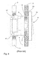
- Fig. 4 there is shown a prior art installation box 1 mounted behind a board 2 such as a plaster board of a wall. Conduits 3 are connected to the installation box 1 for leading in and out the electrical wiring to an electrical installation device 4 such as a switch.
- the installation box 1 has a generally cylindrical mounting part 5 in which a spacer 6 may be inserted at a suitable distance to adapt the overall height of the assembly of installation box 1 and spacer 6 to the space between a mounting base (not shown) for the installation box 1 and the board 2.
- the electrical installation device 4 is mounted on the proximal end of the spacer 6 with fastening means such as screws 8 (not visible in Fig.
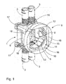
- Fig. 1 the installation box according to the present invention is shown.
- the installation box 1 is with respect to some parts of identical or similar construction to the one in Fig. 4 . Accordingly same reference numerals are used for the same or similar parts throughout the description.
- the installation box 1 has a distal end part comprising the cylindrical compartment 5 having an external diameter.
- the installation box also comprises a second part 9 at the proximal end. Proximal end is to be understood the one facing the front the installation box is installed in a wall.
- the second part comprises an essentially plane proximal end surface 10.
- the second part has a recess 11 in said otherwise essentially plane end surface 10 for accommodating said electrical installation device 4, not shown in Fig. 1 .
- the recess 11 has dimensions across said end surface 10, which are larger than said external diameter of the cylindrical compartment 5. Thereby a bottom surface 12 of the recess 11 is provided.
- the proximal end part is larger than the external diameter of the cylindrical compartment.
- an aperture 13 is formed in the bottom surface 12 to allow e.g. wires to be drawn from the installation device 4 in the recess 11 to the conduits 3 at the bottom of the installation box 1, i.e. at the distal end, the bottom surface 12 presents shoulders or ledges around said aperture 13. These shoulders or ledges may serve as backing and support for the installation device 4.
- the aperture 13 is preferably arranged centrally so as to match the rotational symmetry of the recess 11. This facilitates the positioning of the spacer 6, as the e.g. depicted square recess will have an fourth order symmetry, thus allowing identical mounting at four positions spaced angular apart by 90°.
- the side length of the square or, to be precise, the distance between opposite sides 18 of the square of the recess 11 in the end surface is thus, preferably, matched to the base dimensions of the known installation box 1, i.e. from corner 17 to corner 17.
- the proximal end surface 10 surrounding the recess 11.
- the perimeter of the proximal end surface 10 is circular.
- a circular perimeter is preferred because this matches a circular hole, which, in turn, is very easy to provide correctly by the electrician, using a hole saw and the existing magnetic locating means and seeker already provided for the installation box 1 and the prior art spacer 6.
- the recess 11 on the other hand has a generally polygonal shape, in the illustrated embodiment more specifically a square shape with slightly rounded corners following the perimeter of the proximal end surface. Other generally polygonal shapes, symmetrical or not, such as rectangular, hexagonal or octagonal could of course also be used. In fact the recess 11 need not be a polygon at all, but could e.g. be circular.
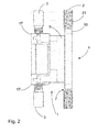
- the combination of the recess 11 and the proximal end surface 10 allows the proximal end surface 10 to lie flush with the front surface 21 of the board 2, thus replacing the board 2 as support for the installation device 4.
- the hole necessary in the board 2 needs to be larger as compared to known solutions. Consequently, as can be seen by comparison between Figs. 3 and 4 the faceplate 14 of the installation device 4 overlaps the board 2 far less, the board thus provides less support if the installation device 4, such as the illustrated switch, is operated, e.g. struck hard by hand and or operated with a tip of a shoe. This in turn means an increased risk of the installation device 4 becoming loose from the installation box 1.
- the larger hole allows a larger part of the installation device to be accommodated at the level of the board, which in turn allows the thickness of the faceplate 14 to be reduced to about 2-3 mm.
- the proximal end surface 10 of the second part of the installation box extends from the proximal end of the spacer 6.
- This embodiment provides for the use of flush installations devices with the use existing known installation devices, which the electrician is used to work with and comfortable about installing, and which is already in production.
- the electrician may use existing techniques for the installation of the installation box 1, compatibility between a known installation box 1 and receptacle spacer according to the mentioned alternative embodiment, also means that the decision about the use of flush mounting installation devices or traditional need not be taken at an early stage in construction or refurbishing of a building.
- the spacer 6 of the invention may be constructed with different lengths of the first cylindrical mounting part 9.
- the fact that the recess 11 is larger than the external diameter of the cylindrical mounting part 9, and that consequently the perimeter of the proximal end surface 10 is even larger, may provide a problem when several installation boxes 1 are mounted side by side to accommodate several installation devices or ganged installation devices sharing a common front plate 14.
- the proximal end of the installation box is therefore adapted to allow the removal of at least a part of the proximal end surface 10 along sides of said generally polygonal shaped recess 11. Preferably this is done by reducing the thickness of the material of the receptacle or by suitable perforations along preferred breaking lines.
- the bottom 12 of the recess 11 has a shape corresponding to the polygonal shape at the proximal end surface 10, i.e. a generally square shape with cut away corners.
- Four main breaking lines 15 indicated by an interrupted line is provided along the four sides of the square.
- Eight secondary breaking lines 16 are provided perpendicular to the main breaking lines 15 at the end thereof i.e. at the transition between the sides of the square and the cut away corners.
- This provides four circle segments, which may individually be broken off leaving the recess open at the respective side (or sides), where the circle segment has been broken off.
- This allows the recesses 11 of two or more adjacent proximal end parts to form one common recess for accommodating a ganged installation device 4. Still, however, the holes for each of the proximal end parts may be provided using the hole saw, with which the electrician is familiar.
- main breaking lines in other places than at the bottom 12 of the recess 11 of the proximal end part. They might also or instead be located at the proximal end surface 10, i.e. at the edge 18 of the recess 11. This would leave an upstanding wall separating the recesses 11 of adjacent installation boxes 1, but still allowing the use of installation boxes 1 mounted side by side.
Landscapes
- Engineering & Computer Science (AREA)
- Architecture (AREA)
- Civil Engineering (AREA)
- Structural Engineering (AREA)
- Connection Or Junction Boxes (AREA)
Applications Claiming Priority (1)
| Application Number | Priority Date | Filing Date | Title |
|---|---|---|---|
| DKPA201170639 | 2011-11-23 |
Publications (2)
| Publication Number | Publication Date |
|---|---|
| EP2597743A1 true EP2597743A1 (de) | 2013-05-29 |
| EP2597743B1 EP2597743B1 (de) | 2017-07-19 |
Family
ID=47191637
Family Applications (1)
| Application Number | Title | Priority Date | Filing Date |
|---|---|---|---|
| EP12193652.0A Active EP2597743B1 (de) | 2011-11-23 | 2012-11-21 | Installationskasten zur Montage an eine elektrische Installationsvorrichtung |
Country Status (1)
| Country | Link |
|---|---|
| EP (1) | EP2597743B1 (de) |
Cited By (2)
| Publication number | Priority date | Publication date | Assignee | Title |
|---|---|---|---|---|
| EP3799236A1 (de) * | 2019-09-26 | 2021-03-31 | Schneider Electric Industries SAS | Teleskopische abstandsringanordnung für einen elektrischen installationskasten |
| EP3654474B1 (de) * | 2018-11-16 | 2022-01-05 | Schneider Electric Industries SAS | Elektroinstallationskastenanordnung |
Citations (7)
| Publication number | Priority date | Publication date | Assignee | Title |
|---|---|---|---|---|
| DE2312605A1 (de) * | 1973-03-14 | 1974-09-19 | Paul Dahl | Zweiteilige installationsdose |
| DE2506725A1 (de) * | 1974-02-18 | 1975-08-21 | Boras Elprodukter Ab | Dosenkoerper fuer elektrische steck- oder verteilerdosen o.dgl. |
| EP0293614A2 (de) * | 1987-06-02 | 1988-12-07 | Raimund Andris GmbH & Co. KG | Hohlwanddose für elektrische Installationseinrichtungen, insbesondere für Schalter, Steckdosen od. dgl. |
| EP1659668A2 (de) * | 2004-11-22 | 2006-05-24 | Kaiser GmbH & Co. KG | Installationsdose für elektrotechnische Zwecke sowie Anordnung zu deren Installation |
| EP1926192A1 (de) * | 2006-11-24 | 2008-05-28 | Capri-Codec SAS | Gehäuse für Trennwand in Trockenbauweise, mit axial fixierten Laschen und axial verschiebbaren Außenstützen |
| EP2259400A2 (de) * | 2009-06-01 | 2010-12-08 | Tomi Pajunpää | Elektrischer Installationskasten und Installationsverfahren für den elektrischen Installationskasten |
| US8148634B1 (en) * | 2009-06-12 | 2012-04-03 | Arlington Industries, Inc. | Electrical box assembly for mounting and supporting a security camera or fixture |
Family Cites Families (3)
| Publication number | Priority date | Publication date | Assignee | Title |
|---|---|---|---|---|
| DE19636500C2 (de) * | 1996-09-09 | 2002-11-07 | Abb Patent Gmbh | Wassergeschütztes Installationsgerät |
| FR2812788B1 (fr) * | 2000-08-07 | 2003-08-08 | Aventis Pasteur | Boitier etanche pour l'encastrement d'un appareillage dans une paroi |
| BE1019288A4 (nl) * | 2010-04-12 | 2012-05-08 | Niko Nv | Montagedoos voor inbouw in een wand. |
-
2012
- 2012-11-21 EP EP12193652.0A patent/EP2597743B1/de active Active
Patent Citations (7)
| Publication number | Priority date | Publication date | Assignee | Title |
|---|---|---|---|---|
| DE2312605A1 (de) * | 1973-03-14 | 1974-09-19 | Paul Dahl | Zweiteilige installationsdose |
| DE2506725A1 (de) * | 1974-02-18 | 1975-08-21 | Boras Elprodukter Ab | Dosenkoerper fuer elektrische steck- oder verteilerdosen o.dgl. |
| EP0293614A2 (de) * | 1987-06-02 | 1988-12-07 | Raimund Andris GmbH & Co. KG | Hohlwanddose für elektrische Installationseinrichtungen, insbesondere für Schalter, Steckdosen od. dgl. |
| EP1659668A2 (de) * | 2004-11-22 | 2006-05-24 | Kaiser GmbH & Co. KG | Installationsdose für elektrotechnische Zwecke sowie Anordnung zu deren Installation |
| EP1926192A1 (de) * | 2006-11-24 | 2008-05-28 | Capri-Codec SAS | Gehäuse für Trennwand in Trockenbauweise, mit axial fixierten Laschen und axial verschiebbaren Außenstützen |
| EP2259400A2 (de) * | 2009-06-01 | 2010-12-08 | Tomi Pajunpää | Elektrischer Installationskasten und Installationsverfahren für den elektrischen Installationskasten |
| US8148634B1 (en) * | 2009-06-12 | 2012-04-03 | Arlington Industries, Inc. | Electrical box assembly for mounting and supporting a security camera or fixture |
Cited By (2)
| Publication number | Priority date | Publication date | Assignee | Title |
|---|---|---|---|---|
| EP3654474B1 (de) * | 2018-11-16 | 2022-01-05 | Schneider Electric Industries SAS | Elektroinstallationskastenanordnung |
| EP3799236A1 (de) * | 2019-09-26 | 2021-03-31 | Schneider Electric Industries SAS | Teleskopische abstandsringanordnung für einen elektrischen installationskasten |
Also Published As
| Publication number | Publication date |
|---|---|
| EP2597743B1 (de) | 2017-07-19 |
Similar Documents
| Publication | Publication Date | Title |
|---|---|---|
| US10443822B2 (en) | Lighting fixture with multiple configurations for different junction box configurations | |
| US20150136437A1 (en) | Efficient installation electrical hardware system and method of use | |
| US6756541B1 (en) | Electrical outlet box with mounting means | |
| US20100176138A1 (en) | System and method for mounting electrical devices | |
| US6452097B1 (en) | Method and device for installing wallboard over a previously installed junction box | |
| US8148634B1 (en) | Electrical box assembly for mounting and supporting a security camera or fixture | |
| US7449633B2 (en) | Electrical box for concrete walls | |
| US7390965B2 (en) | Temporary covers for electrical boxes | |
| US20100071220A1 (en) | Laser Centering Tool | |
| CN110382952B (zh) | 用于将设备齐平安装的紧固系统和齐平式安装的设备 | |
| EP2597743B1 (de) | Installationskasten zur Montage an eine elektrische Installationsvorrichtung | |
| CA2939876C (en) | Floor box assembly with retainer | |
| US7114967B2 (en) | Built-in electric contact enclosure and mounting method | |
| WO2010008778A2 (en) | System and method for mounting electrical devices | |
| US20080219789A1 (en) | Electrical housing knockout device and method | |
| US6804891B1 (en) | Door and drawer pull jig | |
| US20070062717A1 (en) | Device for junction box | |
| US11283253B1 (en) | Adaptable toggle boxes | |
| US8985817B1 (en) | Lamp guard | |
| ES2806093T3 (es) | Una placa de montaje para una unidad interior de un aire acondicionado y un procedimiento para montar una unidad interior | |
| US11444442B1 (en) | Adaptable toggle boxes | |
| US7425680B2 (en) | Ceiling lamp junction box assembly | |
| US20130319719A1 (en) | Recess Can Adapter | |
| US8079556B2 (en) | Lighting fixture mounting platform | |
| ES2667321T3 (es) | Caja para instalar y cablear dispositivos eléctricos |
Legal Events
| Date | Code | Title | Description |
|---|---|---|---|
| PUAI | Public reference made under article 153(3) epc to a published international application that has entered the european phase |
Free format text: ORIGINAL CODE: 0009012 |
|
| AK | Designated contracting states |
Kind code of ref document: A1 Designated state(s): AL AT BE BG CH CY CZ DE DK EE ES FI FR GB GR HR HU IE IS IT LI LT LU LV MC MK MT NL NO PL PT RO RS SE SI SK SM TR |
|
| AX | Request for extension of the european patent |
Extension state: BA ME |
|
| 17P | Request for examination filed |
Effective date: 20131129 |
|
| RBV | Designated contracting states (corrected) |
Designated state(s): AL AT BE BG CH CY CZ DE DK EE ES FI FR GB GR HR HU IE IS IT LI LT LU LV MC MK MT NL NO PL PT RO RS SE SI SK SM TR |
|
| 17Q | First examination report despatched |
Effective date: 20160301 |
|
| GRAP | Despatch of communication of intention to grant a patent |
Free format text: ORIGINAL CODE: EPIDOSNIGR1 |
|
| INTG | Intention to grant announced |
Effective date: 20170130 |
|
| GRAS | Grant fee paid |
Free format text: ORIGINAL CODE: EPIDOSNIGR3 |
|
| GRAA | (expected) grant |
Free format text: ORIGINAL CODE: 0009210 |
|
| RAP1 | Party data changed (applicant data changed or rights of an application transferred) |
Owner name: SCHNEIDER ELECTRIC DANMARK A/S |
|
| AK | Designated contracting states |
Kind code of ref document: B1 Designated state(s): AL AT BE BG CH CY CZ DE DK EE ES FI FR GB GR HR HU IE IS IT LI LT LU LV MC MK MT NL NO PL PT RO RS SE SI SK SM TR |
|
| REG | Reference to a national code |
Ref country code: GB Ref legal event code: FG4D |
|
| REG | Reference to a national code |
Ref country code: CH Ref legal event code: EP |
|
| REG | Reference to a national code |
Ref country code: IE Ref legal event code: FG4D |
|
| REG | Reference to a national code |
Ref country code: AT Ref legal event code: REF Ref document number: 911247 Country of ref document: AT Kind code of ref document: T Effective date: 20170815 |
|
| REG | Reference to a national code |
Ref country code: DE Ref legal event code: R096 Ref document number: 602012034650 Country of ref document: DE |
|
| REG | Reference to a national code |
Ref country code: FR Ref legal event code: PLFP Year of fee payment: 6 |
|
| REG | Reference to a national code |
Ref country code: SE Ref legal event code: TRGR |
|
| REG | Reference to a national code |
Ref country code: NL Ref legal event code: FP |
|
| REG | Reference to a national code |
Ref country code: LT Ref legal event code: MG4D |
|
| REG | Reference to a national code |
Ref country code: AT Ref legal event code: MK05 Ref document number: 911247 Country of ref document: AT Kind code of ref document: T Effective date: 20170719 |
|
| REG | Reference to a national code |
Ref country code: NO Ref legal event code: T2 Effective date: 20170719 |
|
| PG25 | Lapsed in a contracting state [announced via postgrant information from national office to epo] |
Ref country code: AT Free format text: LAPSE BECAUSE OF FAILURE TO SUBMIT A TRANSLATION OF THE DESCRIPTION OR TO PAY THE FEE WITHIN THE PRESCRIBED TIME-LIMIT Effective date: 20170719 Ref country code: HR Free format text: LAPSE BECAUSE OF FAILURE TO SUBMIT A TRANSLATION OF THE DESCRIPTION OR TO PAY THE FEE WITHIN THE PRESCRIBED TIME-LIMIT Effective date: 20170719 Ref country code: LT Free format text: LAPSE BECAUSE OF FAILURE TO SUBMIT A TRANSLATION OF THE DESCRIPTION OR TO PAY THE FEE WITHIN THE PRESCRIBED TIME-LIMIT Effective date: 20170719 |
|
| PG25 | Lapsed in a contracting state [announced via postgrant information from national office to epo] |
Ref country code: RS Free format text: LAPSE BECAUSE OF FAILURE TO SUBMIT A TRANSLATION OF THE DESCRIPTION OR TO PAY THE FEE WITHIN THE PRESCRIBED TIME-LIMIT Effective date: 20170719 Ref country code: IS Free format text: LAPSE BECAUSE OF FAILURE TO SUBMIT A TRANSLATION OF THE DESCRIPTION OR TO PAY THE FEE WITHIN THE PRESCRIBED TIME-LIMIT Effective date: 20171119 Ref country code: GR Free format text: LAPSE BECAUSE OF FAILURE TO SUBMIT A TRANSLATION OF THE DESCRIPTION OR TO PAY THE FEE WITHIN THE PRESCRIBED TIME-LIMIT Effective date: 20171020 Ref country code: BG Free format text: LAPSE BECAUSE OF FAILURE TO SUBMIT A TRANSLATION OF THE DESCRIPTION OR TO PAY THE FEE WITHIN THE PRESCRIBED TIME-LIMIT Effective date: 20171019 Ref country code: PL Free format text: LAPSE BECAUSE OF FAILURE TO SUBMIT A TRANSLATION OF THE DESCRIPTION OR TO PAY THE FEE WITHIN THE PRESCRIBED TIME-LIMIT Effective date: 20170719 Ref country code: ES Free format text: LAPSE BECAUSE OF FAILURE TO SUBMIT A TRANSLATION OF THE DESCRIPTION OR TO PAY THE FEE WITHIN THE PRESCRIBED TIME-LIMIT Effective date: 20170719 Ref country code: LV Free format text: LAPSE BECAUSE OF FAILURE TO SUBMIT A TRANSLATION OF THE DESCRIPTION OR TO PAY THE FEE WITHIN THE PRESCRIBED TIME-LIMIT Effective date: 20170719 |
|
| REG | Reference to a national code |
Ref country code: DE Ref legal event code: R097 Ref document number: 602012034650 Country of ref document: DE |
|
| PG25 | Lapsed in a contracting state [announced via postgrant information from national office to epo] |
Ref country code: DK Free format text: LAPSE BECAUSE OF FAILURE TO SUBMIT A TRANSLATION OF THE DESCRIPTION OR TO PAY THE FEE WITHIN THE PRESCRIBED TIME-LIMIT Effective date: 20170719 Ref country code: RO Free format text: LAPSE BECAUSE OF FAILURE TO SUBMIT A TRANSLATION OF THE DESCRIPTION OR TO PAY THE FEE WITHIN THE PRESCRIBED TIME-LIMIT Effective date: 20170719 Ref country code: CZ Free format text: LAPSE BECAUSE OF FAILURE TO SUBMIT A TRANSLATION OF THE DESCRIPTION OR TO PAY THE FEE WITHIN THE PRESCRIBED TIME-LIMIT Effective date: 20170719 |
|
| PLBE | No opposition filed within time limit |
Free format text: ORIGINAL CODE: 0009261 |
|
| STAA | Information on the status of an ep patent application or granted ep patent |
Free format text: STATUS: NO OPPOSITION FILED WITHIN TIME LIMIT |
|
| PG25 | Lapsed in a contracting state [announced via postgrant information from national office to epo] |
Ref country code: SK Free format text: LAPSE BECAUSE OF FAILURE TO SUBMIT A TRANSLATION OF THE DESCRIPTION OR TO PAY THE FEE WITHIN THE PRESCRIBED TIME-LIMIT Effective date: 20170719 Ref country code: EE Free format text: LAPSE BECAUSE OF FAILURE TO SUBMIT A TRANSLATION OF THE DESCRIPTION OR TO PAY THE FEE WITHIN THE PRESCRIBED TIME-LIMIT Effective date: 20170719 Ref country code: SM Free format text: LAPSE BECAUSE OF FAILURE TO SUBMIT A TRANSLATION OF THE DESCRIPTION OR TO PAY THE FEE WITHIN THE PRESCRIBED TIME-LIMIT Effective date: 20170719 Ref country code: IT Free format text: LAPSE BECAUSE OF FAILURE TO SUBMIT A TRANSLATION OF THE DESCRIPTION OR TO PAY THE FEE WITHIN THE PRESCRIBED TIME-LIMIT Effective date: 20170719 |
|
| 26N | No opposition filed |
Effective date: 20180420 |
|
| PG25 | Lapsed in a contracting state [announced via postgrant information from national office to epo] |
Ref country code: MC Free format text: LAPSE BECAUSE OF FAILURE TO SUBMIT A TRANSLATION OF THE DESCRIPTION OR TO PAY THE FEE WITHIN THE PRESCRIBED TIME-LIMIT Effective date: 20170719 |
|
| GBPC | Gb: european patent ceased through non-payment of renewal fee |
Effective date: 20171121 |
|
| PG25 | Lapsed in a contracting state [announced via postgrant information from national office to epo] |
Ref country code: CH Free format text: LAPSE BECAUSE OF NON-PAYMENT OF DUE FEES Effective date: 20171130 Ref country code: LI Free format text: LAPSE BECAUSE OF NON-PAYMENT OF DUE FEES Effective date: 20171130 |
|
| PG25 | Lapsed in a contracting state [announced via postgrant information from national office to epo] |
Ref country code: LU Free format text: LAPSE BECAUSE OF NON-PAYMENT OF DUE FEES Effective date: 20171121 Ref country code: SI Free format text: LAPSE BECAUSE OF FAILURE TO SUBMIT A TRANSLATION OF THE DESCRIPTION OR TO PAY THE FEE WITHIN THE PRESCRIBED TIME-LIMIT Effective date: 20170719 |
|
| REG | Reference to a national code |
Ref country code: IE Ref legal event code: MM4A |
|
| PG25 | Lapsed in a contracting state [announced via postgrant information from national office to epo] |
Ref country code: MT Free format text: LAPSE BECAUSE OF NON-PAYMENT OF DUE FEES Effective date: 20171121 |
|
| REG | Reference to a national code |
Ref country code: FR Ref legal event code: PLFP Year of fee payment: 7 |
|
| PG25 | Lapsed in a contracting state [announced via postgrant information from national office to epo] |
Ref country code: IE Free format text: LAPSE BECAUSE OF NON-PAYMENT OF DUE FEES Effective date: 20171121 |
|
| PG25 | Lapsed in a contracting state [announced via postgrant information from national office to epo] |
Ref country code: GB Free format text: LAPSE BECAUSE OF NON-PAYMENT OF DUE FEES Effective date: 20171121 |
|
| PG25 | Lapsed in a contracting state [announced via postgrant information from national office to epo] |
Ref country code: HU Free format text: LAPSE BECAUSE OF FAILURE TO SUBMIT A TRANSLATION OF THE DESCRIPTION OR TO PAY THE FEE WITHIN THE PRESCRIBED TIME-LIMIT; INVALID AB INITIO Effective date: 20121121 |
|
| PG25 | Lapsed in a contracting state [announced via postgrant information from national office to epo] |
Ref country code: CY Free format text: LAPSE BECAUSE OF NON-PAYMENT OF DUE FEES Effective date: 20170719 |
|
| PG25 | Lapsed in a contracting state [announced via postgrant information from national office to epo] |
Ref country code: MK Free format text: LAPSE BECAUSE OF FAILURE TO SUBMIT A TRANSLATION OF THE DESCRIPTION OR TO PAY THE FEE WITHIN THE PRESCRIBED TIME-LIMIT Effective date: 20170719 |
|
| PG25 | Lapsed in a contracting state [announced via postgrant information from national office to epo] |
Ref country code: TR Free format text: LAPSE BECAUSE OF FAILURE TO SUBMIT A TRANSLATION OF THE DESCRIPTION OR TO PAY THE FEE WITHIN THE PRESCRIBED TIME-LIMIT Effective date: 20170719 |
|
| PG25 | Lapsed in a contracting state [announced via postgrant information from national office to epo] |
Ref country code: PT Free format text: LAPSE BECAUSE OF FAILURE TO SUBMIT A TRANSLATION OF THE DESCRIPTION OR TO PAY THE FEE WITHIN THE PRESCRIBED TIME-LIMIT Effective date: 20170719 |
|
| PG25 | Lapsed in a contracting state [announced via postgrant information from national office to epo] |
Ref country code: AL Free format text: LAPSE BECAUSE OF FAILURE TO SUBMIT A TRANSLATION OF THE DESCRIPTION OR TO PAY THE FEE WITHIN THE PRESCRIBED TIME-LIMIT Effective date: 20170719 |
|
| PGFP | Annual fee paid to national office [announced via postgrant information from national office to epo] |
Ref country code: FR Payment date: 20250908 Year of fee payment: 14 |
|
| PGFP | Annual fee paid to national office [announced via postgrant information from national office to epo] |
Ref country code: SE Payment date: 20250910 Year of fee payment: 14 |
|
| PGFP | Annual fee paid to national office [announced via postgrant information from national office to epo] |
Ref country code: NL Payment date: 20251003 Year of fee payment: 14 |
|
| PGFP | Annual fee paid to national office [announced via postgrant information from national office to epo] |
Ref country code: DE Payment date: 20250923 Year of fee payment: 14 |
|
| PGFP | Annual fee paid to national office [announced via postgrant information from national office to epo] |
Ref country code: NO Payment date: 20251113 Year of fee payment: 14 |
|
| PGFP | Annual fee paid to national office [announced via postgrant information from national office to epo] |
Ref country code: FI Payment date: 20251113 Year of fee payment: 14 |
|
| PGFP | Annual fee paid to national office [announced via postgrant information from national office to epo] |
Ref country code: BE Payment date: 20251003 Year of fee payment: 14 |