EP2598231B1 - Filtrationsverfahren für den betrieb eines filtrationsmoduls mit gaszuführung an seiner permeatseite zur vermeidung von permeatrückfluss - Google Patents
Filtrationsverfahren für den betrieb eines filtrationsmoduls mit gaszuführung an seiner permeatseite zur vermeidung von permeatrückfluss Download PDFInfo
- Publication number
- EP2598231B1 EP2598231B1 EP11736193.1A EP11736193A EP2598231B1 EP 2598231 B1 EP2598231 B1 EP 2598231B1 EP 11736193 A EP11736193 A EP 11736193A EP 2598231 B1 EP2598231 B1 EP 2598231B1
- Authority
- EP
- European Patent Office
- Prior art keywords
- space
- permeate
- filter element
- liquid
- filtration
- Prior art date
- Legal status (The legal status is an assumption and is not a legal conclusion. Google has not performed a legal analysis and makes no representation as to the accuracy of the status listed.)
- Active
Links
Images


Classifications
-
- B—PERFORMING OPERATIONS; TRANSPORTING
- B01—PHYSICAL OR CHEMICAL PROCESSES OR APPARATUS IN GENERAL
- B01D—SEPARATION
- B01D65/00—Accessories or auxiliary operations, in general, for separation processes or apparatus using semi-permeable membranes
- B01D65/02—Membrane cleaning or sterilisation ; Membrane regeneration
-
- B—PERFORMING OPERATIONS; TRANSPORTING
- B01—PHYSICAL OR CHEMICAL PROCESSES OR APPARATUS IN GENERAL
- B01D—SEPARATION
- B01D61/00—Processes of separation using semi-permeable membranes, e.g. dialysis, osmosis or ultrafiltration; Apparatus, accessories or auxiliary operations specially adapted therefor
- B01D61/02—Reverse osmosis; Hyperfiltration ; Nanofiltration
- B01D61/10—Accessories; Auxiliary operations
-
- B—PERFORMING OPERATIONS; TRANSPORTING
- B01—PHYSICAL OR CHEMICAL PROCESSES OR APPARATUS IN GENERAL
- B01D—SEPARATION
- B01D61/00—Processes of separation using semi-permeable membranes, e.g. dialysis, osmosis or ultrafiltration; Apparatus, accessories or auxiliary operations specially adapted therefor
- B01D61/14—Ultrafiltration; Microfiltration
- B01D61/20—Accessories; Auxiliary operations
-
- B—PERFORMING OPERATIONS; TRANSPORTING
- B01—PHYSICAL OR CHEMICAL PROCESSES OR APPARATUS IN GENERAL
- B01D—SEPARATION
- B01D65/00—Accessories or auxiliary operations, in general, for separation processes or apparatus using semi-permeable membranes
-
- B—PERFORMING OPERATIONS; TRANSPORTING
- B01—PHYSICAL OR CHEMICAL PROCESSES OR APPARATUS IN GENERAL
- B01D—SEPARATION
- B01D2311/00—Details relating to membrane separation process operations and control
- B01D2311/06—Specific process operations in the permeate stream
-
- B—PERFORMING OPERATIONS; TRANSPORTING
- B01—PHYSICAL OR CHEMICAL PROCESSES OR APPARATUS IN GENERAL
- B01D—SEPARATION
- B01D2311/00—Details relating to membrane separation process operations and control
- B01D2311/13—Use of sweep gas
-
- B—PERFORMING OPERATIONS; TRANSPORTING
- B01—PHYSICAL OR CHEMICAL PROCESSES OR APPARATUS IN GENERAL
- B01D—SEPARATION
- B01D2313/00—Details relating to membrane modules or apparatus
- B01D2313/26—Specific gas distributors or gas intakes
-
- B—PERFORMING OPERATIONS; TRANSPORTING
- B01—PHYSICAL OR CHEMICAL PROCESSES OR APPARATUS IN GENERAL
- B01D—SEPARATION
- B01D2315/00—Details relating to the membrane module operation
- B01D2315/10—Cross-flow filtration
-
- B—PERFORMING OPERATIONS; TRANSPORTING
- B01—PHYSICAL OR CHEMICAL PROCESSES OR APPARATUS IN GENERAL
- B01D—SEPARATION
- B01D2321/00—Details relating to membrane cleaning, regeneration, sterilization or to the prevention of fouling
- B01D2321/04—Backflushing
-
- B—PERFORMING OPERATIONS; TRANSPORTING
- B01—PHYSICAL OR CHEMICAL PROCESSES OR APPARATUS IN GENERAL
- B01D—SEPARATION
- B01D2321/00—Details relating to membrane cleaning, regeneration, sterilization or to the prevention of fouling
- B01D2321/20—By influencing the flow
- B01D2321/2033—By influencing the flow dynamically
Definitions
- the invention relates to the field of filtration modules which are used for the filtration of liquids.
- Such modules are known in a wide variety of variants and mostly comprise a housing with one or more filter elements positioned therein which divide the space inside the housing in a feeding side and permeate side.
- One type of filtration modules is based upon so-called dead-end filtration in which liquid to be filtered is fed to the feeding side, from there is passed through the filter element(s), the solids being trapped in the filter and permeate (filtered liquid) is released at the permeate side.
- Another type is based upon so-called cross-flow filtration in which the majority of the liquid flows tangentially across the filtering surface rather than into the filter. The liquid is passed at positive pressure relative to the permeate side.
- a portion of the liquid which is smaller than the pore size of the filter passes there through as permeate, everything else is retained on the feeding side as retentate.
- the tangential motion of the bulk of the liquid across the filter causes trapped particles to be rubbed of the filtering surface. This means that a cross-flow filtration module can operate for a relative long period of time at relatively high solids loads in the liquid without the filter getting blinded.
- EP-0 208 450 shows an embodiment of a cross-flow filtration module that is used for the filtration of beer.
- This module comprises a longitudinal cylindrical housing inside which a bundle of tubular ceramic membrane elements is provided. Unfiltered beer is fed via a liquid feed at the lower side of the module and there enters the inner feeding spaces of the tubular membrane elements. Clear permeate passes through the membrane walls, there enters a permeate space which is left clear around the outer sides of the membrane elements, and from there is drawn of via permeate outlets. Retentate is drawn off via a retentate outlet at the upper side of the module where it leaves the inner feeding spaces of the tubular membrane elements again. The retentate is then circulated via a cooler and a pump back again to the liquid feed at the lower side of the module.
- TMP Trans Membrane Pressure
- US 2007/0158256 shows a filtration module having a membrane with on the left a feeding side with a liquid feed and a retentate outlet, and with on the right a permeate side with a permeate outlet.
- a liquid to be filtered is fed via the liquid feed into the feed side.
- This liquid partly permeates through the membrane towards the permeate side and there is removed as permeate via the permeate outlet.
- the part of the liquid which does not permeate through the membrane is removed as retentate via the retentate outlet.
- Both at the feed side and at the permeate side a cross-flow of liquid flowing along the membrane is achieved during filtration.
- a disadvantage is that the extra pumps needed to obtain the required cross-flow/sweep flow along both sides of the membrane, make the installation expensive, consume lots of energy, and thus makes this filtration module rather expensive during use.
- US 2009/0069619 schematically shows a membrane module having a liquid feed, a retentate outlet and a permeate outlet.
- a part of the liquid which is delivered via the liquid feed by-passes the membrane module unfiltered via a branch and is mixed with filtered permeate coming out of the permeate outlet.
- This mixture of filtered permeate and unfiltered liquid then arrives in an operation unit, such as an isomerisation reactor, after which it leaves the system as a treated product stream.
- the by-passing of unfiltered liquid aims to provide a high purity retentate fraction with less membrane surface area than would be required without the by-pass.
- US-2009/0217777 shows a method of concentrating an analyte that is present in a liquid.
- This method starts with the concentration of the liquid by passing it through a filtration module of which one or more ultra filter membranes are such that the analyte is unable to pass through it.
- Filtered liquid component not containing the analyte then forms permeate, while the liquid and analyte staying behind form retentate.
- the filtration process is ended, after which the collecting of the thus formed retentate is started.
- the permeate side of the module is flushed with a gas.
- the retentate side is flushed with a mixture of a gas and a liquid.
- the retentate solution flushed out can then be collected and includes the concentrated analyte.
- the present invention aims to overcome one or more of the abovementioned disadvantages, or to provide a usable alternative.
- the invention aims to provide a method for operation of a filtration module which can be used effectively for a longer period of time while at the same time the operational costs are lowered.
- a filtration method for operating a filtration module makes use of a module of the type which comprises a housing with at least one filter element positioned therein.
- the filter element defines a first space in the housing at a feeding side of its filtering surface and a second space at the opposite side of the filtering surface, the so-called permeate side.
- a liquid feed is provided which opens out in the first space at the feeding side of the filter element.
- a liquid permeate outlet is provided which is in flow communication with the second space at the permeate side of the filter element.
- the filter element is placed in an upright position. The permeate outlet is positioned at a lower end of the filter element.
- a gas feed which opens out in the second space at the permeate side of the filter element.
- the method comprises the feeding of pressurized gas into the second space during filtration. This pressurized gas then is able to fill up an upper part of the second space. This has the great advantage that at this upper part of the second space, permeate can no longer be present. Even if the local Trans Membrane Pressure (TMP) at this upper part gets negative, a negative flux of already filtered permeate flowing back from the permeate side to the feeding side can not occur at the location of this upper part, simply because permeate is not present there.
- TMP Trans Membrane Pressure
- the invention is used in a cross-flow filtration module which is provided with a retentate outlet which, like the liquid feed, is also in flow communication with the first space at the feeding side of the filter element.
- the retentate outlet is provided at another level than the liquid feed along the filter element. Because of a pressure drop of the liquid between the liquid feed and the retentate outlet, during filtration, the liquid is forced to flow across the filtering surface from the liquid feed towards the retentate outlet.
- the liquid feed is positioned at or near a lower part of the filter element and, in the case of cross-flow filtration, the retentate outlet is then preferably positioned at or near an upper part of the filter element.
- This direction of the pressure drop has the positive effect that the maximum local TMP occurs at the lower part of the filter element, which in turn has the effect that the maximum flux takes place at this lower part. Since the pressurized gas is present in the upper part of the second space it is then possible to have the level of permeate in the lower part of the second space connect as much as possible to the height of the filter element where a positive flux of permeate still occurs.
- the gas feed is positioned at a level above the permeate outlet. In that way the gas which is fed into the second space during filtration, immediately enters that part of the second space which it needs to fill up during this filtration in order to prevent the negative backflow of permeate. Nevertheless, if in an embodiment it is desired for a certain amount of the gas to get mixed with the permeate, then it is also possible to provide the gas feed at a lower level, that is to say at a level where permeate is actually flowing. This may even be at a level below the permeate outlet.
- the filter element can have all kinds of forms and shapes, for example flat or tubular, and can have all kinds of pore sizes.
- it is a membrane filter element.
- the membrane filter element can be used for micro-filtration, with pores in a range of 0.1-10 microns, but also for ultra-filtration, nano-filtration or reverse osmosis when the pores are chosen smaller. Because of the small pore sizes with a membrane filter element, pressurized gas shall not easily start penetrating from the permeate side towards the feeding side.
- the membrane filter element is made hydrophilic. This has the effect that gas is blocked from flowing through the filter element because of capillary pressure inside the filter element passages, in particular the membrane pores.
- the capillary properties of the membrane structure cause that the membrane is wetted and that high pressures are required before the gas can start permeating through the membrane.
- the membrane filter element however can also be made hydrophobic if desired.
- a control unit is provided which is designed for adapting the gas pressure of the pressurized gas in the upper part of the second space in dependence of certain measured control parameters.
- control parameters can for example be the yield in permeate drawn off via the permeate outlet, and/or pressures at one or more locations inside the module, and/or permeate level inside the second space.
- the gas pressure is adapted each time by the control unit to a value which makes it possible to keep withdrawing a certain desired yield of permeate via the permeate outlet during filtration.
- the gas pressure can be adapted each time by the control unit to a value which is substantially equal to or lower than the average liquid pressure in the first space at the feeding side of the filter element during filtration. This prevents too much gas from flowing towards the feeding side.
- the control unit adapt the gas pressure at the beginning of a filtration cycle to a value which corresponds to a certain maximum starting level of permeate at the permeate side. In particular this starting level is at least lower than half the height of the filter element during filtration. More in particular this starting level lies between 5-25% of the height.
- the gas can for example be air or carbon dioxide or nitrogen or any other suitable gas. If for example the liquid to be filtered is beer, then using carbon dioxide has the advantage that it is no problem if some of the gas gets mixed with the permeate and leaves the second space together with the permeate.
- the invention also relates to a filtration module for performing the above described method during a filtration cycle with cross-flow filtration.
- the inventive thought can also be used during a cleaning cycle of the above described filtration module, in particular during a backwash of the filter element.
- pressurized cleaning liquid is fed to the second space at the permeate side of the filter element, for example via a separate cleaning liquid inlet or by connecting the permeate outlet to a cleaning liquid reservoir.
- the cleaning liquid then flows in the backwards direction through the filter element and flushes out any contamination which has gotten trapped therein.
- the thus backwashed cleaning liquid together with the washed out contamination particles can then be discharged from the first space at the feeding side of the filter element, for example via the liquid feed and/or, in the case of cross-flow filtration, via the retentate outlet or by a separate cleaning liquid outlet.
- the cleaning liquid can be directed purposively. Should the pressurized gas not be there to force the cleaning liquid to flow through the most contaminated lower parts of the filter element, then the cleaning liquid would seek the way of the least resistance, that is to say first flow through the least contaminated upper parts of the filter element.
- the cleaning liquid may be any suitable liquid, for example water, but that it may also be formed by earlier obtained permeate itself.
- an installation for the filtering of a liquid comprises a storage vessel 1, a feed pump 2, a recirculation pump 3 and a cross-flow filtration module 4.
- the module 4 comprises a housing 5 inside which a membrane filter element 7 is placed.
- the element 7 is placed in a fully upright position in which it extends vertical from the bottom to the top of the housing 5.
- the element 7 divides the interior space of the housing 5 in a first space 10 at the feeding side and a second space 11 at the permeate side.
- the first space 10 at its lower side connects to a liquid feed 14 and at its upper side connects to a retentate outlet 15.
- the second space 11 at its lower side connects to a permeate outlet 17 and at its upper side connects to a gas feed 18.
- the gas feed 18 via a pump 19 can be fed with pressurized gas from a gas buffer 20.
- liquid to be filtered for example unfiltered beer
- liquid feed 14 into the first space 10.
- liquid feed 14 is pumped via the liquid feed 14 into the first space 10.
- This filtered permeate accumulates in the lower part of the second space 11 and from there is discharged via the permeate outlet 17.
- pressurized gas is fed to the second space 11 via the gas feed 18. This gas fills up the upper part of the second space 11. This can also be clearly seen in fig. 2 .
- the second space 11 is not fed with gas, as shown in fig. 3 , then it completely fills itself with permeate. If for example the feeding pressure of the liquid to be filtered at the liquid feed 14 is 3.0 bar and the outlet pressure of the retained retentate at the retentate outlet 15 is 2.4 bar, and the outlet pressure of the filtered permeate at the permeate outlet is 2.8 bar, then the local Trans Membrane Pressure (TMP) can be calculated.
- TMP Trans Membrane Pressure
- the TMP is the driving force for the permeation/filtration.
- the local TMP has a maximum value of 0.2 bar at the bottom side of the filter element 7, gradually decreases upwardly along the filter element 7, and at some point is equal to zero, and from there gets to be negative. All along the lower part of the filter element 7 where the local TMP is positive, there is a positive flux of permeate flowing from the first space 10 towards the second space 11. All along the upper part of the filter element 7 where the local TMP is negative, there is a negative backflow of already filtered permeate flowing back from the second space 11 towards the first space 10.
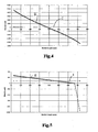
- Fig. 4 shows this situation at start up of a new filtration process for a beer filtration module having a filter element with a total height of 750 mm.
- the thin horizontal line I shows the average flux of permeate which leaves the module via the permeate outlet 17. This average flux here is 80 l/m2.h.
- the thick downwardly sloping line Il is the local flux varying over the height of the filter element 7, which is necessary to obtain the desired average flux.
- the local flux needs to vary from more than 4500 to -4200 l/m2.h in order to be able to obtain the desired average flux of merely 80 l/m2.h.
- In the upper part of the module there is a huge amount of already filtered permeate flowing back to the feeding side. This huge amount of backflow needs to be compensated for by a huge positive flow of permeate at the lower part of the module.
- FIG. 5 shows the situation after only 10 minutes, assuming that the average flux is still desired to be the same 80 l/m2.h.
- the differences between the positive flux along the lower part of the filter element and the negative flux along the upper part of the filter element are still huge, whereas the absolute values have gotten lower. This means that a large part of the filter element 7 has gotten contaminated and it becomes necessary to clean the filter element.
- the second space 11 is fed with gas, as shown in fig. 2 , then it can partly fill itself with permeate and partly with the gas. With this the pressure of the gas is controlled such that it is substantially equal to the pressure of the permeate. If the feeding pressure of the liquid to be filtered at the liquid feed 14 is still 3.0 bar and the outlet pressure of the retained retentate at the retentate outlet 15 is still 2.4 bar, and the outlet pressure of the filtered permeate at the permeate outlet is kept at 2.8 bar, then the local Trans Membrane Pressure (TMP) stays the same as in the gasless situation of fig. 3 .
- TMP Trans Membrane Pressure
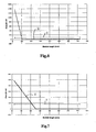
- Fig. 6 shows this gas filled situation according to the invention at start up of a new filtration process again for a beer filtration module having a filter element with a total height of 750 mm.
- the thin horizontal line I shows the same average flux of permeate which leaves the module via the permeate outlet 17.
- the thick partly downwardly sloping line II is the local flux varying over the height of the filter element 7, which is necessary to obtain the desired average flux.
- the local flux now only needs to vary from close to 1400 to 0 l/m2.h in order to be able to obtain the desired average flux of merely 80 l/m2.h.
- the lower part of the module only needs to have a positive flow which is large enough to be able to obtain the desired average flux.
- Fig. 7 shows the situation after 10 minutes, assuming that the average flux is still desired to be the same 80 l/m2.h. As can be seen the positive flux still only needs to occur along a relative small lower part of the filter element and a negative flux still can not occur along the upper part of the filter element. This means that the filter element 7 has gotten hardly contaminated and it is not necessary at all to clean the filter element.
- fig. 8 shows the average TMP as a function of the filtration time on the one hand for the state of the art gasless situation (Normal) and on the other hand for the inventive gas filled situation (+Flux).
- a filtration cycle ends as soon as the average TMP reaches the value 1.2 bar.
- a cleaning cycle starts in the form of a backwashing cycle, after which a new filtration cycle is started.
- the cycles for the gasless situation are indicated with GL
- the cycles for the gas filled situation are indicated with GF.
- the module and filter element placed therein may have different shapes and dimensions.
- the module may be oriented such that its filter element is placed in a partially upright position, that is to say under an angle with respect to the horizontal, in particular an angle of at least 45 degrees. The more vertical the filter element is placed however, the more easily the permeate level can be managed.
- a number of filter elements for example a bundle of membrane tubes.
- it can also be used for the filtration of all kinds of other liquids, for example water.
- the invention provides a cost effective, efficient and user friendly filtration module and method for operating it, during filtration and if desired also during cleaning.
Landscapes
- Chemical & Material Sciences (AREA)
- Chemical Kinetics & Catalysis (AREA)
- Engineering & Computer Science (AREA)
- Water Supply & Treatment (AREA)
- Nanotechnology (AREA)
- Separation Using Semi-Permeable Membranes (AREA)
Claims (10)
- Filtrationsverfahren zum Betrieb eines Filtrationsmoduls,
wobei das Modul (4) umfasst:- ein Gehäuse (5) mit wenigstens einem darin angeordneten Filterelement (7), wobei das Filterelement (7) in dem Gehäuse (5) einen ersten Raum (10) an einer Beschickungs- bzw. Aufgabeseite der Filterfläche und einen zweiten Raum (11) an einer gegenüberliegenden Permeatseite definiert;- einen Flüssigkeitszufuhr (14), welcher sich in den ersten Raum (10) an der Beschickungsseite des Filterelements (7) öffnet; und- einen Auslass (17) für ein flüssiges Permeat in Flusskommunikation mit dem zweiten Raum (11) an der Permeatseite des Filterelements (7);wobei das Verfahren die Schritte umfasst:
wobei das Filterelement (7) in einer aufrechten Position angeordnet ist, der Auslass (17) des flüssigen Permeats an einem unteren Ende des Filterelements (7) positioniert ist, und
eine Gaszufuhr (18), welche bereitgestellt ist, so dass sie sich in den zweiten Raum (11) an der Permeatseite des Filterelements (7) öffnet,- Zuführen von unter Druck gesetzter Flüssigkeit, welche gefiltert werden soll, in den ersten Raum (10) an der Beschickungsseite des Filterelements (7);- Abgeben des gefilterten flüssigen Permeats aus dem zweiten Raum (11) an der Permeatseite des Filterelements (7); und- Zuführen von unter Druck gesetztem Gas in den zweiten Raum (11) an der Permeatseite des Filterelements (7),
wobei ein Cross-Flow-Filtrationsmodul verwendet wird, mit einem Retentatauslass (15) in Flusskommunikation mit dem ersten Raum (10) an der Beschickungsseite des Filterelements (7), wobei der Retentatauslass auf einem anderen Niveau als die Flüssigkeitszufuhr (14) entlang des Filterelements (7) angeordnet ist,
wobei nicht filtriertes Retentat über den Retentat-Auslass (15) aus dem ersten Raum (10) an der Beschickungsseite des Filterelements (7) abgegeben wird, so dass ein Druckverlust der Flüssigkeit zwischen der Flüssigkeitszufuhr (14) und dem Retentatauslass (15) erzeugt wird, um die Flüssigkeit zu zwingen von der Flüssigkeitszufuhr (14) über das Filterelement (7) zu den Retentat-Auslass (15) zu fließen,
dadurch gekennzeichnet, dass
der Schritt des Zuführens von unter Druck gesetztem Gas in den zweiten Raum (11) während der Filtration gleichzeitig mit den Schritten des Zuführens der unter Druck gesetzten Flüssigkeit, welche gefiltert werden soll, in den ersten Raum (10) und dem Abgeben des gefilterten flüssigen Permeat aus dem zweiten Raum (11) durchgeführt wird, wobei sich der zweite Raum (11) teilweise selbst mit dem flüssigen Permeat und teilweise mit dem unter Druck gesetzten Gas füllt. - Filtrationsverfahren nach Anspruch 1, wobei ein Teil des zweiten Raums (11), der sich selbst mit dem Gas füllt, auf einem Teil des zweiten Raums (11) zu liegen kommt, welcher sich selbst mit dem flüssigen Permeat füllt.
- Filtrationsverfahren nach Anspruch 2, wobei das unter Druck gesetzte Gas in den zweiten Raum (11) zugeführt wird damit das flüssige Permeat einen Teil des zweiten Raums (11) auffüllt welcher mit einer Höhe des Filterelements (7) zusammengeht wo ein positiver Vorwärtsfluss des flüssigen Permeats aus dem ersten Raum (10) in den zweiten Raum (11) während der Filtration auftritt.
- Filtrationsverfahren nach einem der vorangehenden Ansprüche, wobei ein Cross-Flow-Filtrationsmodul dass der Retentat-Auslass (15) an einem oberen Ende des Filterelements (7) hat und dass die Flüssigkeitszufuhr (14) an einem unteren Ende des Filterelements (7) positioniert hat, wobei ein Druckverlust der Flüssigkeit zwischen der Flüssigkeitszufuhr (14) und dem Retentat-Auslass (15) erzeugt wird welcher von dem oberen zu dem unteren Ende des Filterelements (7) verläuft.
- Filtrationsverfahren nach einem der vorangehenden Ansprüche, wobei ein Cross-Flow-Filtrationsmodul (4) verwendet wird, bei welchem die Gaszufuhr (18) an einem oberhalb des Auslasses (17) für flüssiges Permeat angeordneten Niveau positioniert ist, wobei das unter Druck gesetzte Gas direkt in den oberen Teil des zweiten Raums (11) zugeführt wird.
- Filtrationsverfahren nach einem der vorangehenden Ansprüche, wobei ein hydrophiles Filterelement verwendet wird, um zu verhindern, dass Gas durch das Filterelement (7) fließt.
- Filtrationsverfahren nach einem der vorangehenden Ansprüche, wobei der Gasdruck des Gases, welches über die Gaszufuhr (18) in den zweiten Raum (11) an der Permeatseite des Filterelements (7) zugeführt wird, mittels einer Kontrolleinheit auf einen Wert gesteuert werden kann, welcher im Wesentlichen dem mittleren Flüssigkeitsdruck in dem ersten Raum (10) an der Zuführseite des Filterelements (7) während der Filtration entspricht oder niedriger ist als dieser.
- Filtrationsverfahren nach einem der vorangehenden Ansprüche, wobei der Gasdruck des Gases, welches über die Gaszufuhr (18) in den zweiten Raum (11) zugeführt wird, mittels einer Kontrolleinheit in Abhängigkeit der Erzielung einer gewünschten Ausbeute des flüssigen Permeats, welches aus dem Permeatauslass (17) während der Filtration abgegeben wird, gesteuert werden kann.
- Filtrationsverfahren nach einem der vorangehenden Ansprüche, wobei der Gasdruck des Gases, welches über die Gaszufuhr (18) in den zweiten Raum (11) zugeführt wird, mittels einer Kontrolleinheit zu einem Beginn eines Filtrationszykluses angepasst wird, um ein gewünschtes Startniveau des flüssigen Permeats an der Permeatseite zu erzielen, insbesondere ein Niveau, welches niedriger ist als die halbe Höhe des Filterelements (7) während der Filtration, insbesondere zwischen 5-25 % der Höhe.
- Filtrationsverfahren nach einem der vorangehenden Ansprüche, wobei der Gasdruck des Gases, welches in den zweiten Raum (11) zugeführt wird, stufenweise über die Fitrationsdauer verringert wird.
Priority Applications (1)
| Application Number | Priority Date | Filing Date | Title |
|---|---|---|---|
| PL11736193T PL2598231T3 (pl) | 2010-07-30 | 2011-07-14 | Sposób filtracji przy eksploatacji modułu filtracyjnego z podajnikiem gazu po stronie permeatu w celu zapobiegania przepływowi wstecznemu permeatu |
Applications Claiming Priority (2)
| Application Number | Priority Date | Filing Date | Title |
|---|---|---|---|
| NL2005177A NL2005177C2 (en) | 2010-07-30 | 2010-07-30 | A filtration module with gas feed at its permeate side to prevent backflow of permeate. |
| PCT/NL2011/050511 WO2012015298A2 (en) | 2010-07-30 | 2011-07-14 | A filtration method for operating a filtration module with gas feed at its permeate side to prevent backflow of permeate |
Publications (2)
| Publication Number | Publication Date |
|---|---|
| EP2598231A2 EP2598231A2 (de) | 2013-06-05 |
| EP2598231B1 true EP2598231B1 (de) | 2014-04-23 |
Family
ID=43618794
Family Applications (1)
| Application Number | Title | Priority Date | Filing Date |
|---|---|---|---|
| EP11736193.1A Active EP2598231B1 (de) | 2010-07-30 | 2011-07-14 | Filtrationsverfahren für den betrieb eines filtrationsmoduls mit gaszuführung an seiner permeatseite zur vermeidung von permeatrückfluss |
Country Status (16)
| Country | Link |
|---|---|
| US (1) | US9504964B2 (de) |
| EP (1) | EP2598231B1 (de) |
| JP (1) | JP5699398B2 (de) |
| CN (1) | CN103118768B (de) |
| AU (1) | AU2011283263B2 (de) |
| BR (1) | BR112013002094B1 (de) |
| CA (1) | CA2806170C (de) |
| DK (1) | DK2598231T3 (de) |
| EC (1) | ECSP13012463A (de) |
| ES (1) | ES2478493T3 (de) |
| NL (1) | NL2005177C2 (de) |
| PH (1) | PH12013500188A1 (de) |
| PL (1) | PL2598231T3 (de) |
| RU (1) | RU2572963C2 (de) |
| WO (1) | WO2012015298A2 (de) |
| ZA (1) | ZA201300832B (de) |
Families Citing this family (1)
| Publication number | Priority date | Publication date | Assignee | Title |
|---|---|---|---|---|
| FR3139999A1 (fr) | 2022-09-22 | 2024-03-29 | Bucher Vaslin | Procédé de gestion du colmatage de membrane d’un dispositif de filtration tangentiel |
Family Cites Families (15)
| Publication number | Priority date | Publication date | Assignee | Title |
|---|---|---|---|---|
| US3756408A (en) * | 1972-06-15 | 1973-09-04 | Osmonics Inc | Separation system |
| GB2176715A (en) | 1985-06-27 | 1987-01-07 | Apv Int Ltd | Beer filtration |
| FR2697172B1 (fr) * | 1992-10-26 | 1994-12-02 | Commissariat Energie Atomique | Procédé de décolmatage automatique d'une unité d'ultrafiltration ou de microfiltration et installation mettant en Óoeuvre le procédé. |
| JP2605921Y2 (ja) * | 1993-12-27 | 2000-09-04 | エヌオーケー株式会社 | 濾過装置 |
| JPH09892A (ja) * | 1995-06-19 | 1997-01-07 | Nok Corp | ろ過膜の洗浄方法 |
| US5958243A (en) * | 1996-07-11 | 1999-09-28 | Zenon Environmental Inc. | Apparatus and method for membrane filtration with enhanced net flux |
| RU2226120C2 (ru) * | 2000-09-12 | 2004-03-27 | Закрытое акционерное общество "Обнинский центр естественных наук и технологий" | Устройство для фильтрации жидкости и способ регенерации фильтрующих элементов |
| NL1019565C2 (nl) * | 2001-12-14 | 2003-06-17 | Norit Membraan Tech Bv | Membraanfilterbehuizing en werkwijze welke deze toepast. |
| NL1025459C2 (nl) * | 2004-02-11 | 2005-08-12 | Friesland Brands Bv | Inrichting en werkwijze voor micro-of ultrafiltratie. |
| US7169213B2 (en) * | 2004-10-29 | 2007-01-30 | Corning Incorporated | Multi-channel cross-flow porous device |
| US20100025320A1 (en) * | 2006-03-22 | 2010-02-04 | Warren Thomas Johnson | Backwash and cleaning method |
| NL1031926C2 (nl) * | 2006-05-31 | 2007-12-03 | X Flow Bv | Inrichting met een bioreactor en membraanfiltratiemodule voor het behandelen van een inkomend fluïdum. |
| US7812207B2 (en) * | 2007-09-07 | 2010-10-12 | Uop Llc | Membrane separation processes and systems for enhanced permeant recovery |
| US8857279B2 (en) * | 2008-03-03 | 2014-10-14 | William P. Hanson | Analyte screening and detection systems and methods |
| RU85837U1 (ru) * | 2009-02-24 | 2009-08-20 | Борис Яковлевич Басин | Мембранный модуль (варианты) и мембранное устройство (варианты) |
-
2010
- 2010-07-30 NL NL2005177A patent/NL2005177C2/en not_active IP Right Cessation
-
2011
- 2011-07-14 AU AU2011283263A patent/AU2011283263B2/en not_active Ceased
- 2011-07-14 PH PH1/2013/500188A patent/PH12013500188A1/en unknown
- 2011-07-14 JP JP2013521732A patent/JP5699398B2/ja active Active
- 2011-07-14 ES ES11736193.1T patent/ES2478493T3/es active Active
- 2011-07-14 BR BR112013002094-6A patent/BR112013002094B1/pt not_active IP Right Cessation
- 2011-07-14 CN CN201180038427.5A patent/CN103118768B/zh not_active Expired - Fee Related
- 2011-07-14 RU RU2013108832/05A patent/RU2572963C2/ru not_active IP Right Cessation
- 2011-07-14 DK DK11736193.1T patent/DK2598231T3/da active
- 2011-07-14 WO PCT/NL2011/050511 patent/WO2012015298A2/en not_active Ceased
- 2011-07-14 EP EP11736193.1A patent/EP2598231B1/de active Active
- 2011-07-14 PL PL11736193T patent/PL2598231T3/pl unknown
- 2011-07-14 CA CA2806170A patent/CA2806170C/en not_active Expired - Fee Related
- 2011-07-14 US US13/812,554 patent/US9504964B2/en active Active
-
2013
- 2013-01-31 ZA ZA2013/00832A patent/ZA201300832B/en unknown
- 2013-02-27 EC ECSP13012463 patent/ECSP13012463A/es unknown
Also Published As
| Publication number | Publication date |
|---|---|
| JP5699398B2 (ja) | 2015-04-08 |
| RU2572963C2 (ru) | 2016-01-20 |
| BR112013002094B1 (pt) | 2020-02-18 |
| BR112013002094A2 (pt) | 2016-05-24 |
| CN103118768A (zh) | 2013-05-22 |
| ZA201300832B (en) | 2014-04-30 |
| US20130228514A1 (en) | 2013-09-05 |
| ES2478493T3 (es) | 2014-07-22 |
| NL2005177C2 (en) | 2012-01-31 |
| US9504964B2 (en) | 2016-11-29 |
| JP2013533113A (ja) | 2013-08-22 |
| EP2598231A2 (de) | 2013-06-05 |
| WO2012015298A3 (en) | 2012-04-05 |
| CN103118768B (zh) | 2015-05-13 |
| HK1185030A1 (en) | 2014-02-07 |
| AU2011283263A1 (en) | 2013-02-28 |
| CA2806170A1 (en) | 2012-02-02 |
| RU2013108832A (ru) | 2014-09-10 |
| ECSP13012463A (es) | 2013-04-30 |
| PL2598231T3 (pl) | 2014-09-30 |
| CA2806170C (en) | 2018-08-28 |
| PH12013500188A1 (en) | 2022-10-24 |
| WO2012015298A2 (en) | 2012-02-02 |
| AU2011283263B2 (en) | 2014-09-18 |
| DK2598231T3 (da) | 2014-07-21 |
Similar Documents
| Publication | Publication Date | Title |
|---|---|---|
| EP0213157B1 (de) | Konzentrierung von feststoffen in einer suspension | |
| AU576424B2 (en) | Concentration of solids in a suspension | |
| AU2008309404A1 (en) | A portable water purification device | |
| JPH03154620A (ja) | 膜分離装置 | |
| US20150375174A1 (en) | Integrated ultrafiltration and reverse osmosis desalination systems | |
| WO2011158559A1 (ja) | 膜モジュールの洗浄方法 | |
| JP5326571B2 (ja) | ろ過処理方法 | |
| US7422690B2 (en) | Filtering system | |
| EP3349883B1 (de) | System und verfahren zum chemischen spülen eines filtrationssystems | |
| EP2598231B1 (de) | Filtrationsverfahren für den betrieb eines filtrationsmoduls mit gaszuführung an seiner permeatseite zur vermeidung von permeatrückfluss | |
| WO2017046214A1 (en) | Filtration system and method for backwashing a filtration system | |
| KR101392755B1 (ko) | 관형막을 이용한 수처리시스템 | |
| OA16307A (en) | A filtration method for operating a filtration module with gas feed at its permeate side to prevent backflow of permeate. | |
| JP2018143970A (ja) | 濃縮システムおよび濃縮方法 | |
| JP3943748B2 (ja) | 膜ろ過装置の洗浄方法 | |
| JP2010188250A (ja) | 水処理方法 | |
| JP2005254192A (ja) | 膜分離装置および膜分離方法 | |
| HK1185030B (en) | A filtration method for operating a filtration module with gas feed at its permeate side to prevent backflow of permeate | |
| JPH0824590A (ja) | 高濃度有機液の濾過方法 | |
| JPH07185210A (ja) | 濾過装置 | |
| JP2006218341A (ja) | 水処理方法および装置 | |
| JP2026017561A (ja) | 膜ろ過装置及びろ過膜の洗浄方法 | |
| JP2005329393A (ja) | 膜モジュール複合体を用いた濾過運転方法 | |
| JP2000271455A (ja) | スパイラル型膜エレメントおよびスパイラル型膜モジュールの運転方法および洗浄方法 | |
| JP2007222740A (ja) | 縦型分離膜モジュールの洗浄方法 |
Legal Events
| Date | Code | Title | Description |
|---|---|---|---|
| PUAI | Public reference made under article 153(3) epc to a published international application that has entered the european phase |
Free format text: ORIGINAL CODE: 0009012 |
|
| 17P | Request for examination filed |
Effective date: 20130221 |
|
| AK | Designated contracting states |
Kind code of ref document: A2 Designated state(s): AL AT BE BG CH CY CZ DE DK EE ES FI FR GB GR HR HU IE IS IT LI LT LU LV MC MK MT NL NO PL PT RO RS SE SI SK SM TR |
|
| AX | Request for extension of the european patent |
Extension state: ME |
|
| RAX | Requested extension states of the european patent have changed |
Extension state: ME Payment date: 20130221 |
|
| GRAJ | Information related to disapproval of communication of intention to grant by the applicant or resumption of examination proceedings by the epo deleted |
Free format text: ORIGINAL CODE: EPIDOSDIGR1 |
|
| GRAP | Despatch of communication of intention to grant a patent |
Free format text: ORIGINAL CODE: EPIDOSNIGR1 |
|
| INTG | Intention to grant announced |
Effective date: 20131211 |
|
| GRAS | Grant fee paid |
Free format text: ORIGINAL CODE: EPIDOSNIGR3 |
|
| GRAA | (expected) grant |
Free format text: ORIGINAL CODE: 0009210 |
|
| AK | Designated contracting states |
Kind code of ref document: B1 Designated state(s): AL AT BE BG CH CY CZ DE DK EE ES FI FR GB GR HR HU IE IS IT LI LT LU LV MC MK MT NL NO PL PT RO RS SE SI SK SM TR |
|
| AX | Request for extension of the european patent |
Extension state: ME |
|
| REG | Reference to a national code |
Ref country code: GB Ref legal event code: FG4D |
|
| REG | Reference to a national code |
Ref country code: CH Ref legal event code: EP |
|
| REG | Reference to a national code |
Ref country code: AT Ref legal event code: REF Ref document number: 663462 Country of ref document: AT Kind code of ref document: T Effective date: 20140515 |
|
| REG | Reference to a national code |
Ref country code: IE Ref legal event code: FG4D |
|
| REG | Reference to a national code |
Ref country code: DE Ref legal event code: R096 Ref document number: 602011006420 Country of ref document: DE Effective date: 20140605 |
|
| REG | Reference to a national code |
Ref country code: NL Ref legal event code: T3 |
|
| REG | Reference to a national code |
Ref country code: DK Ref legal event code: T3 Effective date: 20140716 |
|
| REG | Reference to a national code |
Ref country code: ES Ref legal event code: FG2A Ref document number: 2478493 Country of ref document: ES Kind code of ref document: T3 Effective date: 20140722 |
|
| REG | Reference to a national code |
Ref country code: LT Ref legal event code: MG4D |
|
| REG | Reference to a national code |
Ref country code: PL Ref legal event code: T3 |
|
| PG25 | Lapsed in a contracting state [announced via postgrant information from national office to epo] |
Ref country code: FI Free format text: LAPSE BECAUSE OF FAILURE TO SUBMIT A TRANSLATION OF THE DESCRIPTION OR TO PAY THE FEE WITHIN THE PRESCRIBED TIME-LIMIT Effective date: 20140423 Ref country code: GR Free format text: LAPSE BECAUSE OF FAILURE TO SUBMIT A TRANSLATION OF THE DESCRIPTION OR TO PAY THE FEE WITHIN THE PRESCRIBED TIME-LIMIT Effective date: 20140724 Ref country code: NO Free format text: LAPSE BECAUSE OF FAILURE TO SUBMIT A TRANSLATION OF THE DESCRIPTION OR TO PAY THE FEE WITHIN THE PRESCRIBED TIME-LIMIT Effective date: 20140723 Ref country code: CY Free format text: LAPSE BECAUSE OF FAILURE TO SUBMIT A TRANSLATION OF THE DESCRIPTION OR TO PAY THE FEE WITHIN THE PRESCRIBED TIME-LIMIT Effective date: 20140423 Ref country code: LT Free format text: LAPSE BECAUSE OF FAILURE TO SUBMIT A TRANSLATION OF THE DESCRIPTION OR TO PAY THE FEE WITHIN THE PRESCRIBED TIME-LIMIT Effective date: 20140423 Ref country code: BG Free format text: LAPSE BECAUSE OF FAILURE TO SUBMIT A TRANSLATION OF THE DESCRIPTION OR TO PAY THE FEE WITHIN THE PRESCRIBED TIME-LIMIT Effective date: 20140723 Ref country code: IS Free format text: LAPSE BECAUSE OF FAILURE TO SUBMIT A TRANSLATION OF THE DESCRIPTION OR TO PAY THE FEE WITHIN THE PRESCRIBED TIME-LIMIT Effective date: 20140823 |
|
| PG25 | Lapsed in a contracting state [announced via postgrant information from national office to epo] |
Ref country code: SE Free format text: LAPSE BECAUSE OF FAILURE TO SUBMIT A TRANSLATION OF THE DESCRIPTION OR TO PAY THE FEE WITHIN THE PRESCRIBED TIME-LIMIT Effective date: 20140423 Ref country code: LV Free format text: LAPSE BECAUSE OF FAILURE TO SUBMIT A TRANSLATION OF THE DESCRIPTION OR TO PAY THE FEE WITHIN THE PRESCRIBED TIME-LIMIT Effective date: 20140423 Ref country code: RS Free format text: LAPSE BECAUSE OF FAILURE TO SUBMIT A TRANSLATION OF THE DESCRIPTION OR TO PAY THE FEE WITHIN THE PRESCRIBED TIME-LIMIT Effective date: 20140423 Ref country code: HR Free format text: LAPSE BECAUSE OF FAILURE TO SUBMIT A TRANSLATION OF THE DESCRIPTION OR TO PAY THE FEE WITHIN THE PRESCRIBED TIME-LIMIT Effective date: 20140423 |
|
| PG25 | Lapsed in a contracting state [announced via postgrant information from national office to epo] |
Ref country code: PT Free format text: LAPSE BECAUSE OF FAILURE TO SUBMIT A TRANSLATION OF THE DESCRIPTION OR TO PAY THE FEE WITHIN THE PRESCRIBED TIME-LIMIT Effective date: 20140825 |
|
| REG | Reference to a national code |
Ref country code: DE Ref legal event code: R097 Ref document number: 602011006420 Country of ref document: DE |
|
| PG25 | Lapsed in a contracting state [announced via postgrant information from national office to epo] |
Ref country code: SK Free format text: LAPSE BECAUSE OF FAILURE TO SUBMIT A TRANSLATION OF THE DESCRIPTION OR TO PAY THE FEE WITHIN THE PRESCRIBED TIME-LIMIT Effective date: 20140423 Ref country code: EE Free format text: LAPSE BECAUSE OF FAILURE TO SUBMIT A TRANSLATION OF THE DESCRIPTION OR TO PAY THE FEE WITHIN THE PRESCRIBED TIME-LIMIT Effective date: 20140423 Ref country code: RO Free format text: LAPSE BECAUSE OF FAILURE TO SUBMIT A TRANSLATION OF THE DESCRIPTION OR TO PAY THE FEE WITHIN THE PRESCRIBED TIME-LIMIT Effective date: 20140423 |
|
| PG25 | Lapsed in a contracting state [announced via postgrant information from national office to epo] |
Ref country code: LU Free format text: LAPSE BECAUSE OF FAILURE TO SUBMIT A TRANSLATION OF THE DESCRIPTION OR TO PAY THE FEE WITHIN THE PRESCRIBED TIME-LIMIT Effective date: 20140714 |
|
| PLBE | No opposition filed within time limit |
Free format text: ORIGINAL CODE: 0009261 |
|
| REG | Reference to a national code |
Ref country code: CH Ref legal event code: PL |
|
| STAA | Information on the status of an ep patent application or granted ep patent |
Free format text: STATUS: NO OPPOSITION FILED WITHIN TIME LIMIT |
|
| 26N | No opposition filed |
Effective date: 20150126 |
|
| PG25 | Lapsed in a contracting state [announced via postgrant information from national office to epo] |
Ref country code: LI Free format text: LAPSE BECAUSE OF NON-PAYMENT OF DUE FEES Effective date: 20140731 Ref country code: CH Free format text: LAPSE BECAUSE OF NON-PAYMENT OF DUE FEES Effective date: 20140731 |
|
| REG | Reference to a national code |
Ref country code: DE Ref legal event code: R097 Ref document number: 602011006420 Country of ref document: DE Effective date: 20150126 |
|
| PG25 | Lapsed in a contracting state [announced via postgrant information from national office to epo] |
Ref country code: SI Free format text: LAPSE BECAUSE OF FAILURE TO SUBMIT A TRANSLATION OF THE DESCRIPTION OR TO PAY THE FEE WITHIN THE PRESCRIBED TIME-LIMIT Effective date: 20140423 |
|
| PG25 | Lapsed in a contracting state [announced via postgrant information from national office to epo] |
Ref country code: MC Free format text: LAPSE BECAUSE OF FAILURE TO SUBMIT A TRANSLATION OF THE DESCRIPTION OR TO PAY THE FEE WITHIN THE PRESCRIBED TIME-LIMIT Effective date: 20140423 Ref country code: SM Free format text: LAPSE BECAUSE OF FAILURE TO SUBMIT A TRANSLATION OF THE DESCRIPTION OR TO PAY THE FEE WITHIN THE PRESCRIBED TIME-LIMIT Effective date: 20140423 |
|
| PG25 | Lapsed in a contracting state [announced via postgrant information from national office to epo] |
Ref country code: MT Free format text: LAPSE BECAUSE OF FAILURE TO SUBMIT A TRANSLATION OF THE DESCRIPTION OR TO PAY THE FEE WITHIN THE PRESCRIBED TIME-LIMIT Effective date: 20140423 |
|
| REG | Reference to a national code |
Ref country code: FR Ref legal event code: PLFP Year of fee payment: 6 |
|
| PG25 | Lapsed in a contracting state [announced via postgrant information from national office to epo] |
Ref country code: HU Free format text: LAPSE BECAUSE OF FAILURE TO SUBMIT A TRANSLATION OF THE DESCRIPTION OR TO PAY THE FEE WITHIN THE PRESCRIBED TIME-LIMIT; INVALID AB INITIO Effective date: 20110714 Ref country code: TR Free format text: LAPSE BECAUSE OF FAILURE TO SUBMIT A TRANSLATION OF THE DESCRIPTION OR TO PAY THE FEE WITHIN THE PRESCRIBED TIME-LIMIT Effective date: 20140423 |
|
| REG | Reference to a national code |
Ref country code: FR Ref legal event code: PLFP Year of fee payment: 7 |
|
| PGFP | Annual fee paid to national office [announced via postgrant information from national office to epo] |
Ref country code: IE Payment date: 20170530 Year of fee payment: 7 |
|
| PGFP | Annual fee paid to national office [announced via postgrant information from national office to epo] |
Ref country code: PL Payment date: 20170601 Year of fee payment: 7 |
|
| PGFP | Annual fee paid to national office [announced via postgrant information from national office to epo] |
Ref country code: IT Payment date: 20170727 Year of fee payment: 7 |
|
| PGFP | Annual fee paid to national office [announced via postgrant information from national office to epo] |
Ref country code: DK Payment date: 20170726 Year of fee payment: 7 |
|
| PG25 | Lapsed in a contracting state [announced via postgrant information from national office to epo] |
Ref country code: MK Free format text: LAPSE BECAUSE OF FAILURE TO SUBMIT A TRANSLATION OF THE DESCRIPTION OR TO PAY THE FEE WITHIN THE PRESCRIBED TIME-LIMIT Effective date: 20140423 |
|
| REG | Reference to a national code |
Ref country code: FR Ref legal event code: PLFP Year of fee payment: 8 |
|
| PG25 | Lapsed in a contracting state [announced via postgrant information from national office to epo] |
Ref country code: AL Free format text: LAPSE BECAUSE OF FAILURE TO SUBMIT A TRANSLATION OF THE DESCRIPTION OR TO PAY THE FEE WITHIN THE PRESCRIBED TIME-LIMIT Effective date: 20140423 |
|
| PGFP | Annual fee paid to national office [announced via postgrant information from national office to epo] |
Ref country code: TR Payment date: 20180704 Year of fee payment: 15 |
|
| REG | Reference to a national code |
Ref country code: DK Ref legal event code: EBP Effective date: 20180731 |
|
| REG | Reference to a national code |
Ref country code: IE Ref legal event code: MM4A |
|
| PG25 | Lapsed in a contracting state [announced via postgrant information from national office to epo] |
Ref country code: IE Free format text: LAPSE BECAUSE OF NON-PAYMENT OF DUE FEES Effective date: 20180714 |
|
| PG25 | Lapsed in a contracting state [announced via postgrant information from national office to epo] |
Ref country code: IT Free format text: LAPSE BECAUSE OF NON-PAYMENT OF DUE FEES Effective date: 20180714 Ref country code: DK Free format text: LAPSE BECAUSE OF NON-PAYMENT OF DUE FEES Effective date: 20180731 |
|
| PGFP | Annual fee paid to national office [announced via postgrant information from national office to epo] |
Ref country code: CZ Payment date: 20190626 Year of fee payment: 9 |
|
| PG25 | Lapsed in a contracting state [announced via postgrant information from national office to epo] |
Ref country code: PL Free format text: LAPSE BECAUSE OF NON-PAYMENT OF DUE FEES Effective date: 20180714 |
|
| REG | Reference to a national code |
Ref country code: AT Ref legal event code: MM01 Ref document number: 663462 Country of ref document: AT Kind code of ref document: T Effective date: 20190714 |
|
| PG25 | Lapsed in a contracting state [announced via postgrant information from national office to epo] |
Ref country code: AT Free format text: LAPSE BECAUSE OF NON-PAYMENT OF DUE FEES Effective date: 20190714 |
|
| PG25 | Lapsed in a contracting state [announced via postgrant information from national office to epo] |
Ref country code: CZ Free format text: LAPSE BECAUSE OF NON-PAYMENT OF DUE FEES Effective date: 20200714 |
|
| P01 | Opt-out of the competence of the unified patent court (upc) registered |
Effective date: 20230613 |
|
| PGFP | Annual fee paid to national office [announced via postgrant information from national office to epo] |
Ref country code: NL Payment date: 20250723 Year of fee payment: 15 |
|
| PGFP | Annual fee paid to national office [announced via postgrant information from national office to epo] |
Ref country code: ES Payment date: 20250819 Year of fee payment: 15 |
|
| PGFP | Annual fee paid to national office [announced via postgrant information from national office to epo] |
Ref country code: DE Payment date: 20250722 Year of fee payment: 15 |
|
| PGFP | Annual fee paid to national office [announced via postgrant information from national office to epo] |
Ref country code: BE Payment date: 20250722 Year of fee payment: 15 Ref country code: GB Payment date: 20250724 Year of fee payment: 15 |
|
| PGFP | Annual fee paid to national office [announced via postgrant information from national office to epo] |
Ref country code: FR Payment date: 20250723 Year of fee payment: 15 |