EP2598407B1 - Procédé de fabrication de récipients moulés par soufflage et récipients moulés par soufflage - Google Patents
Procédé de fabrication de récipients moulés par soufflage et récipients moulés par soufflage Download PDFInfo
- Publication number
- EP2598407B1 EP2598407B1 EP11801555.1A EP11801555A EP2598407B1 EP 2598407 B1 EP2598407 B1 EP 2598407B1 EP 11801555 A EP11801555 A EP 11801555A EP 2598407 B1 EP2598407 B1 EP 2598407B1
- Authority
- EP
- European Patent Office
- Prior art keywords
- container
- ribs
- circumferential
- radial direction
- blow
- Prior art date
- Legal status (The legal status is an assumption and is not a legal conclusion. Google has not performed a legal analysis and makes no representation as to the accuracy of the status listed.)
- Active
Links
Images




Classifications
-
- B—PERFORMING OPERATIONS; TRANSPORTING
- B65—CONVEYING; PACKING; STORING; HANDLING THIN OR FILAMENTARY MATERIAL
- B65D—CONTAINERS FOR STORAGE OR TRANSPORT OF ARTICLES OR MATERIALS, e.g. BAGS, BARRELS, BOTTLES, BOXES, CANS, CARTONS, CRATES, DRUMS, JARS, TANKS, HOPPERS, FORWARDING CONTAINERS; ACCESSORIES, CLOSURES, OR FITTINGS THEREFOR; PACKAGING ELEMENTS; PACKAGES
- B65D23/00—Details of bottles or jars not otherwise provided for
- B65D23/10—Handles
- B65D23/102—Gripping means formed in the walls, e.g. roughening, cavities, projections
-
- B—PERFORMING OPERATIONS; TRANSPORTING
- B29—WORKING OF PLASTICS; WORKING OF SUBSTANCES IN A PLASTIC STATE IN GENERAL
- B29D—PRODUCING PARTICULAR ARTICLES FROM PLASTICS OR FROM SUBSTANCES IN A PLASTIC STATE
- B29D22/00—Producing hollow articles
- B29D22/003—Containers for packaging, storing or transporting, e.g. bottles, jars, cans, barrels, tanks
-
- B—PERFORMING OPERATIONS; TRANSPORTING
- B65—CONVEYING; PACKING; STORING; HANDLING THIN OR FILAMENTARY MATERIAL
- B65D—CONTAINERS FOR STORAGE OR TRANSPORT OF ARTICLES OR MATERIALS, e.g. BAGS, BARRELS, BOTTLES, BOXES, CANS, CARTONS, CRATES, DRUMS, JARS, TANKS, HOPPERS, FORWARDING CONTAINERS; ACCESSORIES, CLOSURES, OR FITTINGS THEREFOR; PACKAGING ELEMENTS; PACKAGES
- B65D1/00—Rigid or semi-rigid containers having bodies formed in one piece, e.g. by casting metallic material, by moulding plastics, by blowing vitreous material, by throwing ceramic material, by moulding pulped fibrous material or by deep-drawing operations performed on sheet material
- B65D1/40—Details of walls
- B65D1/42—Reinforcing or strengthening parts or members
-
- B—PERFORMING OPERATIONS; TRANSPORTING
- B29—WORKING OF PLASTICS; WORKING OF SUBSTANCES IN A PLASTIC STATE IN GENERAL
- B29C—SHAPING OR JOINING OF PLASTICS; SHAPING OF MATERIAL IN A PLASTIC STATE, NOT OTHERWISE PROVIDED FOR; AFTER-TREATMENT OF THE SHAPED PRODUCTS, e.g. REPAIRING
- B29C2949/00—Indexing scheme relating to blow-moulding
- B29C2949/07—Preforms or parisons characterised by their configuration
- B29C2949/0715—Preforms or parisons characterised by their configuration the preform having one end closed
-
- B—PERFORMING OPERATIONS; TRANSPORTING
- B29—WORKING OF PLASTICS; WORKING OF SUBSTANCES IN A PLASTIC STATE IN GENERAL
- B29C—SHAPING OR JOINING OF PLASTICS; SHAPING OF MATERIAL IN A PLASTIC STATE, NOT OTHERWISE PROVIDED FOR; AFTER-TREATMENT OF THE SHAPED PRODUCTS, e.g. REPAIRING
- B29C49/00—Blow-moulding, i.e. blowing a preform or parison to a desired shape within a mould; Apparatus therefor
- B29C49/02—Combined blow-moulding and manufacture of the preform or the parison
- B29C49/06—Injection blow-moulding
-
- B—PERFORMING OPERATIONS; TRANSPORTING
- B29—WORKING OF PLASTICS; WORKING OF SUBSTANCES IN A PLASTIC STATE IN GENERAL
- B29L—INDEXING SCHEME ASSOCIATED WITH SUBCLASS B29C, RELATING TO PARTICULAR ARTICLES
- B29L2031/00—Other particular articles
- B29L2031/712—Containers; Packaging elements or accessories, Packages
- B29L2031/7158—Bottles
-
- B—PERFORMING OPERATIONS; TRANSPORTING
- B65—CONVEYING; PACKING; STORING; HANDLING THIN OR FILAMENTARY MATERIAL
- B65D—CONTAINERS FOR STORAGE OR TRANSPORT OF ARTICLES OR MATERIALS, e.g. BAGS, BARRELS, BOTTLES, BOXES, CANS, CARTONS, CRATES, DRUMS, JARS, TANKS, HOPPERS, FORWARDING CONTAINERS; ACCESSORIES, CLOSURES, OR FITTINGS THEREFOR; PACKAGING ELEMENTS; PACKAGES
- B65D2501/00—Containers having bodies formed in one piece
- B65D2501/0009—Bottles or similar containers with necks or like restricted apertures designed for pouring contents
- B65D2501/0018—Ribs
- B65D2501/0027—Hollow longitudinal ribs
-
- B—PERFORMING OPERATIONS; TRANSPORTING
- B65—CONVEYING; PACKING; STORING; HANDLING THIN OR FILAMENTARY MATERIAL
- B65D—CONTAINERS FOR STORAGE OR TRANSPORT OF ARTICLES OR MATERIALS, e.g. BAGS, BARRELS, BOTTLES, BOXES, CANS, CARTONS, CRATES, DRUMS, JARS, TANKS, HOPPERS, FORWARDING CONTAINERS; ACCESSORIES, CLOSURES, OR FITTINGS THEREFOR; PACKAGING ELEMENTS; PACKAGES
- B65D2501/00—Containers having bodies formed in one piece
- B65D2501/0009—Bottles or similar containers with necks or like restricted apertures designed for pouring contents
- B65D2501/0018—Ribs
- B65D2501/0036—Hollow circonferential ribs
Definitions
- the invention relates to a method for producing a blow molded container having a closable mouth portion, a side wall and a closed bottom.
- the invention further relates to a blow-molded container having a closable mouth portion, a side wall and a closed bottom.
- preforms made of a thermoplastic material for example preforms made of PET (polyethylene terephthalate)
- a blow molding machine has a heating device and a blowing device, in the region of which the previously tempered preform is expanded by biaxial orientation to form a container.
- the expansion takes place with the aid of compressed air, which is introduced into the preform to be expanded.
- the procedural sequence in such an expansion of the preform is in the DE-OS 43 40 291 explained.
- the introductory mentioned introduction of the pressurized gas also includes the introduction of compressed gas into the developing container bubble and the introduction of compressed gas into the preform at the beginning of the blowing process.
- the preforms as well as the blown containers can be transported by means of different handling devices.
- the use of transport mandrels, onto which the preforms are plugged, has proven to be useful.
- the preforms can also be handled with other support devices.
- the use of gripper tongs for handling preforms and the use of expansion mandrels which are insertable into a muzzle region of the preform for mounting are also among the available constructions.
- blow molding stations different embodiments are known.
- blow stations which are arranged on rotating transport wheels, a book-like unfoldability of the mold carrier is frequently encountered. But it is also possible to use relatively movable or differently guided mold carrier.
- fixed blowing stations which are particularly suitable for receiving a plurality of cavities for container molding, typically plates arranged parallel to one another are used as mold carriers.
- the preforms are typically attached to transport mandrels, which either transport the preform through the entire blow molding machine or circulate only in the region of the heating device.
- transport mandrels In a stationary heating of the preforms such that the mouths of the preforms are oriented in the vertical direction downwards, the preforms are usually attached to a sleeve-shaped support member of the transport mandrel.
- a suspended heating of the preforms in which they are oriented with their mouths in the vertical direction upwards, expanding mandrels are introduced into the mouths of the preforms, which clamp the preforms in the rule.
- blow-molded containers are used in a variety of designs for packaging products.
- still or carbonated beverages are bottled in such containers.
- EP 0322 651 discloses such a container.
- a significant cost factor in the production of the containers in question is the weight of the material used.
- the material is relatively expensive, moreover, a heating of the material before the blow molding is required, which has a corresponding energy use result. It is therefore continuously trying to reduce the use of materials and form the blow-molded container with the thinnest possible walls.
- the container requires sufficient stability in a longitudinal direction in order to be able to absorb force loads during filling.
- consumers demand recessed grips to safely grasp and handle the bottle. Corresponding recessed grips reduce the stability.
- an injection-molded preform is tempered and shaped by a blowing process into a container in such a way that the material is shaped in the area of the side wall by the blow molding process such that at least three recessed grips are arranged along an outer circumference of the container each of which is formed at least two longitudinal ribs oriented in a longitudinal direction of the container, which are separated by a likewise longitudinal trough and that within each of the recessed grips at least one circumferential rib is arranged, which extends in a circumferential direction of the container.
- Another object of the present invention is to construct a container of the aforementioned type such that improved stability properties are provided.
- the material is formed in the region of the side wall by blow molding an injection-molded preform such that along an outer periphery of the container at least three recessed grips are arranged between each of which at least two longitudinal ribs oriented in a longitudinal direction of the container are arranged, which are separated by a likewise longitudinal trough from each other and that within each of the recessed grips at least one circumferential rib is arranged, which extends in a circumferential direction of the container.
- the arrangement of at least three recessed grips along the outer periphery of the container assists in a secure manual gripping of the container in any position of the container relative to a user.
- the arrangement of the longitudinal ribs between the recessed grips stabilizes the container in a longitudinal direction.
- the division into at least two separate from a trough longitudinal ribs again improves the stability.
- the arrangement of the longitudinal ribs within the recessed grips stabilizes the container against manual deformation when gripped. In addition, the contour stability during storage is also supported.
- An increased stability when gripping the container is achieved in that extend within the recessed grip at least three peripheral ribs, of which at least one in a radial direction of the container on an ahderen Level is arranged as at least one other of the circumferential ribs.
- An increased stability in gripping the container is achieved in that three circumferential ribs are arranged one above the other in the region of a base in a radial direction of the inner recessed grip.
- a further increase in the mechanical load capacity can be achieved by the fact that the base of the recessed grip in a longitudinal direction of the container in both the vertical upward and vertically downward direction is passed through at least two stepped circumferential ribs in the region of the side wall of the container.
- a good compromise between blow-molding property and high stability is achieved by providing the trough separating the longitudinal fins in a radial direction of the container with a depth corresponding to at most 50 percent of the extension of the longitudinal fins in the radial direction of the container.
- a functional design is achieved in that the recessed grip is provided in a vertical cross-sectional area with a trapezoidal contour.
- a high stability in externally acting forces is achieved in that at least one of the circumferential ribs is limited in a vertical cross-sectional area at least partially circular segment-like and curved in a radial direction to the outside.
- Mutual support of the circumferential ribs is achieved by forming at least two adjacent circumferential ribs relative to each other with an angular transition.
- FIG. 1 shows a blow-molded container (1) having a mouth portion (2), side walls (3) and a bottom (4).
- the mouth portion (2) is provided with an external thread (5) and separated by a support ring (6) from the side walls (3).
- a plurality of feet (7) are arranged, between each of which distances (8) extend.
- the container (1) extends along a longitudinal axis (9).
- recessed grips (10) are arranged along an outer periphery of the container (1) .
- a use of at least three recessed grips (10) is intended.
- the embodiment in FIG. 1 shows the use of five recessed grips (10).
- the recessed grips (10) are arranged in a central region of the container (1) in the direction of the longitudinal axis (9).
- circumferential ribs (11) In a vertically above the recessed grips (10) arranged area of the Container (1) are circumferential ribs (11).
- circumferential ribs (12) are arranged in a region of the container (1) arranged in the vertical direction below the recessed grips (10).
- the ribs (11, 12) are typically realized as in the direction of an interior of the container (1) extending into groove-shaped recesses. But also usable are ring-like outer bulges. In addition, the use is not only intended for circumferential ribs (11, 12), but these can also be realized segmented.
- FIG. 1 shows the use of five circumferential ribs (15) in each of the recessed grips (10).
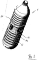
- FIG. 2 illustrated in a perspective view again the construction of the container (1) according to FIG. 1 , In particular, the arrangement of the peripheral ribs (15) within the recessed grips (10) and the outside comparatively flat design of the longitudinal ribs (13) can be seen.
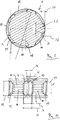
- the horizontal section in FIG. 3 illustrates the depth of the ribs (12).
- FIG. 4 shows in a horizontal section in particular the depth of the recessed grips (10).
- a weight is about 18 grams.
- a size of the container (1) is a diameter (17) in FIG. 3 about 82.8 millimeters and a diameter (18) in FIG. 4 about 76.3 millimeters.
- the extension in the direction of the longitudinal axis (9) is about 309 millimeters.
- the upper ribs (11) extend over a range of about 60 millimeters.
- FIG. 1 shows the use of five ribs (11).
- the ribs (12) extend over a range of about 80 millimeters.
- the embodiment shows the use of six ribs (12).
- FIG. 5 illustrates a horizontal section similar to FIG. 4 with additionally drawn dimensions.
- the diameter (18) is about 85 percent of the outer diameter (19).
- the diameter (18) is about 75 percent to 95 percent of the outside diameter (19).
- the combination of the longitudinal ribs (13) and the trough (14) extends in a circumferential direction of the container (1) over a range of about 20 millimeters. Typically, the width (20) is about 15 to 25 millimeters. In a direction parallel to the radial direction of the container (1) extending direction is a maximum extent of the longitudinal ribs (13) about a quarter of the difference between the diameters (17) and (18). The values are in a range of 0.05 to 0.5 multiplied by the difference between the diameters (17) and (18).
- a depth (22) of the trough (14) measured from a maximum extent of the longitudinal ribs (13) is about 2.5 millimeters.
- a typical range is from 0.5 to 5.0 millimeters.
- the longitudinal ribs (13) have, at least in sections, a cross-sectional area similar to a part of a circular area.
- a diameter (23) of a corresponding circle is about 55 percent of the width (20).
- Typical of the diameter (23) is a range of 40 percent to 70 percent of the width (20).
- FIG. 6 illustrates further exemplary dimensions.
- a height (24) of the recessed grips (10) is about 24 millimeters. Typical for the height (24) is a range of 5 to 32 millimeters.
- a width (25) of the trough (14) is about 2 millimeters. Typical for the width (25) is a range of 1 to 8 millimeters.
- a distance (26) from apex lines (27) of the longitudinal ribs (13) is about 8 millimeters. Typically, for the distance (26) is a range of 6 to 12 millimeters.
- the apex lines (27) define the maximum in a radial direction outwardly extending extent of the longitudinal ribs (13).
- An outer height (28) of the recessed grips (13) is about 5.3 times the in FIG. 5 marked extent (21).
- FIG. 7 illustrates in a further schematic cross-sectional representation of the rib-like contour of the recessed grips (10).
- a trapezoidal cross-sectional area of the recessed grips (10) In the region of a bottom of the recessed grips (10) arranged circumferential ribs (15) have a height (29) of about 1 to 2 millimeters. A height (29) of about 1 millimeter is preferred.
- a curvature radius (30) of these circumferential ribs (15) is about 4 millimeters. Typical for the radius (30) is a range of 3 to 5 millimeters.
- the embodiment according to FIG. 7 shows in the region of the bottom of the recessed grip (10) three juxtaposed circumferential ribs (15) which are arranged with their respective vertex in a common plane.
- FIG. 8 shows the substantially same area of the container (1) as the illustration in FIG. 6 but in a slightly rotated position about the longitudinal axis of the container (1).
- FIG. 9 shows a horizontal section similar to FIG. 4 but with additional dimensions.
- the diameter (18) is about 76.3 millimeters
- the width (20) is about 19.8 millimeters
- the extent (21) about 6.13 millimeters
- the depth (22) about 0.66 millimeters
- the diameter ( 23) about 11 Millimeter.
- FIG. 10 is essentially the same as in FIG. 6 with the following exemplary concrete dimensioning information.
- the height (24) is about 24.8 millimeters, the width (25) about 2.85 millimeters, the distance (26) about 8.0 millimeters and the outer height (28) about 32.3 millimeters.
- an outer width (31) of approximately 19.4 millimeters and an inner width (32) of approximately 17.9 millimeters are shown.
- FIG. 11 illustrated in a highly schematic representation of the recessed grip (10) without a specific representation of the peripheral ribs (15) and the longitudinal ribs (13).
- a transition radius between a base of the recessed grip (10) and the oblique side walls is about 1 to 5 millimeters. Preferred is about 1 millimeter.
- a radius in the transition region between the oblique side walls of the recessed grips (10) and the vertical area of the wall of the container (1) is about 6 millimeters. Applicable for the radius (34) is a range of 2 to 15 millimeters.
- a base height (35) of the base of the recessed grip (10) is about 15 millimeters. Applicable for the base height (35) is a range of 10 to 25 millimeters.
- An angle between the vertical course of the side wall of the container (1) and the oblique side wall of the recessed grip (10) is about 35 degrees. Applicable to the angle (36) is a range of 25 degrees to 45 degrees.
Landscapes
- Engineering & Computer Science (AREA)
- Mechanical Engineering (AREA)
- Ceramic Engineering (AREA)
- Containers Having Bodies Formed In One Piece (AREA)
- Blow-Moulding Or Thermoforming Of Plastics Or The Like (AREA)
- Moulds For Moulding Plastics Or The Like (AREA)
- Processing And Handling Of Plastics And Other Materials For Molding In General (AREA)
Claims (14)
- Procédé de fabrication d'un récipient (1) moulé par soufflage présentant une section d'embouchure (2) pouvant être obturée, une paroi latérale (3) ainsi qu'un fond (4) fermé, caractérisé en ce qu'une préforme moulée par injection est tempérée et transformée par un processus de soufflage en un récipient (1) de façon à ce qu'au niveau de la paroi latérale (3) le processus de moulage par soufflage donne au matériau une forme telle que l'on ait, le long d'une circonférence extérieure du récipient (1), un agencement d'au moins trois concavités de préhension (10) entre lesquelles sont respectivement formées au moins deux nervures longitudinales (13) orientées dans le sens longitudinal du récipient (1), lesquelles sont séparées l'une de l'autre par un creux (14) également longitudinal, et en ce qu'est agencée dans chaque concavités de préhension (10) au moins une nervure circonférentielle (15) s'étendant le long d'une circonférence du récipient (1), la transition verticale aussi bien vers le haut que vers le bas entre la base de la concavité de préhension (10) et la paroi latérale du récipient (1) dans le sens longitudinal de celui-ci étant assurée par au moins deux nervures circonférentielles (15) étagées.
- Procédé selon la revendication 1, caractérisé en ce que, dans la concavité de préhension (10), s'étendent au moins trois nervures circonférentielles (15) dont l'une au moins est, dans un sens radial du récipient (1), agencée sur un autre niveau que l'une au moins des autres nervures circonférentielles (15).
- Procédé selon la revendication 1 ou 2, caractérisé en ce que, dans la zone d'une base de la concavité de préhension (10) intérieure dans le sens radial, trois nervures circonférentielles (15) sont agencées l'une au-dessus de l'autre.
- Procédé selon l'une des revendications 1 à 3, caractérisé en ce que le creux (14) séparant les nervures longitudinales (13) a, en sens radial du récipient (1), une profondeur correspondant à au maximum 50 pour cent de l'extension en sens radial du récipient (1) des nervures longitudinales (13).
- Procédé selon l'une des revendications 1 à 4, caractérisé en ce que, dans un plan de section transversale vertical, la concavité de préhension (10) a un contour de type trapézoïdal.
- Procédé selon l'une des revendications 1 à 5, caractérisé en ce que, dans un plan de section transversale vertical, l'une au moins des nervures circonférentielles (15) est limitée sur une partie au moins de son étendue par une délimitation en forme de segment de cercle et est, en sens radial, bombée vers l'extérieur.
- Procédé selon l'une des revendications 1 à 6, caractérisé en ce qu'au moins deux nervures circonférentielles (15) voisines sont formées avec une transition anguleuse entre elles.
- Récipient (1) moulé par soufflage présentant une section d'embouchure (2) pouvant être obturée, une paroi latérale (3) ainsi qu'un fond (4) fermé, caractérisé en ce que, au niveau de la paroi latérale (3), le moulage par soufflage d'une préforme moulée par injection donne au matériau une forme telle que l'on ait, le long d'une circonférence extérieure du récipient (1), un agencement d'au moins trois concavités de préhension (10) entre lesquelles sont respectivement agencées au moins deux nervures longitudinales (13) orientées dans le sens longitudinal du récipient (1), lesquelles sont séparées l'une de l'autre par un creux (14) également longitudinal, et en ce qu'est agencée dans chaque concavités de préhension (10) au moins une nervure circonférentielle (15) s'étendant le long d'une circonférence du récipient (1), la transition verticale aussi bien vers le haut que vers le bas entre la base de la concavité de préhension (10) et la paroi latérale du récipient (1) étant étagée sur au moins deux nervures circonférentielles (15).
- Récipient selon la revendication 8, caractérisé en ce que la concavité de préhension (10) présente au moins trois nervures circonférentielles (15) dont l'une au moins est, dans un sens radial du récipient (1), agencée sur un autre niveau que l'une au moins des autres nervures circonférentielles (15).
- Récipient selon la revendication 8 ou 9, caractérisé en ce que, dans la zone d'une base de la concavité de préhension (10) intérieure dans le sens radial du récipient (1), au moins trois nervures circonférentielles (15) sont agencées l'une au-dessus de l'autre en sens vertical.
- Récipient selon l'une des revendications 8 à 10, caractérisé en ce que le creux (14) séparant les nervures longitudinales (13) présente, en sens radial du récipient (1), une profondeur correspondant à au maximum 50 pour cent de l'extension en sens radial du récipient (1) des nervures longitudinales (13).
- Récipient selon l'une des revendications 8 à 11, caractérisé en ce que, dans un plan de section transversale vertical, la concavité de préhension (14) présente un contour de type trapézoïdal.
- Récipient selon l'une des revendications 8 à 12, caractérisé en ce que dans un plan de section transversale vertical, l'une au moins des nervures circonférentielles (15) est limitée sur une partie au moins de son étendue par une délimitation en forme de segment de cercle et est, en sens radial du récipient (1), bombée vers l'extérieur.
- Récipient selon l'une des revendications 8 à 13, caractérisé en ce qu'au moins deux nervures circonférentielles (15) voisines forment un angle entre elles.
Applications Claiming Priority (2)
| Application Number | Priority Date | Filing Date | Title |
|---|---|---|---|
| DE102010033377 | 2010-07-29 | ||
| PCT/DE2011/001537 WO2012013188A2 (fr) | 2010-07-29 | 2011-07-26 | Procédé de fabrication de récipients moulés par soufflage et récipients moulés par soufflage |
Publications (2)
| Publication Number | Publication Date |
|---|---|
| EP2598407A2 EP2598407A2 (fr) | 2013-06-05 |
| EP2598407B1 true EP2598407B1 (fr) | 2016-05-11 |
Family
ID=45406312
Family Applications (1)
| Application Number | Title | Priority Date | Filing Date |
|---|---|---|---|
| EP11801555.1A Active EP2598407B1 (fr) | 2010-07-29 | 2011-07-26 | Procédé de fabrication de récipients moulés par soufflage et récipients moulés par soufflage |
Country Status (6)
| Country | Link |
|---|---|
| US (1) | US8939316B2 (fr) |
| EP (1) | EP2598407B1 (fr) |
| CN (1) | CN103097251B (fr) |
| BR (1) | BR112013001917A2 (fr) |
| DE (1) | DE102011108978A1 (fr) |
| WO (1) | WO2012013188A2 (fr) |
Families Citing this family (13)
| Publication number | Priority date | Publication date | Assignee | Title |
|---|---|---|---|---|
| CA155722S (en) * | 2013-09-25 | 2015-02-10 | Sidel Participations | Bottle |
| JP6335475B2 (ja) * | 2013-11-06 | 2018-05-30 | ザ コカ・コーラ カンパニーThe Coca‐Cola Company | プラスチックボトル |
| USD741187S1 (en) * | 2014-04-24 | 2015-10-20 | Societe Des Produits Nestle, Sa | Plastic container |
| USD741186S1 (en) * | 2014-04-24 | 2015-10-20 | Societe Des Produits Nestle Sa | Plastic container |
| USD826059S1 (en) * | 2016-03-25 | 2018-08-21 | Sidel Participations | Bottle |
| DE102016115646A1 (de) * | 2016-08-23 | 2018-03-15 | Krones Ag | Kunststoff-Flasche mit sich kreuzenden Zugbändern |
| US10899493B2 (en) * | 2016-12-29 | 2021-01-26 | Graham Packaging Company, L.P. | Hot-fillable plastic container |
| USD932905S1 (en) * | 2021-02-26 | 2021-10-12 | The Coca-Cola Company | Bottle with a ripple panel |
| USD1019404S1 (en) * | 2022-05-20 | 2024-03-26 | Johnnie Yip | Beverage bottle |
| US12195227B2 (en) * | 2022-07-11 | 2025-01-14 | Krones Inc. | Container having gussets |
| USD1046625S1 (en) | 2022-07-11 | 2024-10-15 | Krones Inc. | Container |
| US12234082B2 (en) * | 2022-07-29 | 2025-02-25 | Brandeis University | Rotationally stabilized wine bottle with rotationally controlling bumpers |
| FR3151577B1 (fr) * | 2023-07-27 | 2025-07-18 | Sidel Participations | Récipient, notamment bouteille, en matière thermoplastique à résistance à la charge verticale améliorée |
Citations (1)
| Publication number | Priority date | Publication date | Assignee | Title |
|---|---|---|---|---|
| EP0322651A2 (fr) * | 1987-12-24 | 1989-07-05 | Continental Pet Technologies, Inc. | Préforme et méthode pour la fabrication de récipient pour remplissage à chaud |
Family Cites Families (22)
| Publication number | Priority date | Publication date | Assignee | Title |
|---|---|---|---|---|
| DE2352926A1 (de) | 1973-10-22 | 1975-04-24 | Heidenreich & Harbeck Gmbh | Verfahren und vorrichtung zum erwaermen eines werkstueckes aus kunststoff |
| US5238129A (en) * | 1985-07-30 | 1993-08-24 | Yoshino Kogyosho Co., Ltd. | Container having ribs and collapse panels |
| FR2625974B1 (fr) * | 1988-01-14 | 1990-04-27 | Sidel Sa | Bouteille en materiau thermoplastique |
| US5178289A (en) * | 1992-02-26 | 1993-01-12 | Continental Pet Technologies, Inc. | Panel design for a hot-fillable container |
| DE4212583A1 (de) | 1992-04-15 | 1993-10-21 | Krupp Corpoplast Masch | Vorrichtung zur Blasformung |
| DE4340291A1 (de) | 1993-11-26 | 1995-06-01 | Krupp Corpoplast Masch | Mehrfachnutzung von Blasluft |
| US5704503A (en) * | 1994-10-28 | 1998-01-06 | Continental Pet Technologies, Inc. | Hot-fillable plastic container with tall and slender panel section |
| US6044997A (en) * | 1998-06-12 | 2000-04-04 | Graham Packaging Company L. P. | Grip dome container |
| DE19906438A1 (de) | 1999-02-16 | 2000-08-17 | Krupp Corpoplast Masch | Verfahren und Vorrichtung zur Übergabe von Behältern |
| JP3842005B2 (ja) | 2000-03-30 | 2006-11-08 | 株式会社吉野工業所 | ボトル胴部の補強リブ |
| US20030000911A1 (en) * | 2001-06-27 | 2003-01-02 | Paul Kelley | Hot-fillable multi-sided blow-molded container |
| JP4675013B2 (ja) * | 2001-09-26 | 2011-04-20 | 株式会社吉野工業所 | ピンチグリップ式ボトル型容器 |
| DE60228980D1 (de) | 2001-09-27 | 2008-10-30 | Yoshino Kogyosho Co Ltd | Kunstharzbehälter mit formfestigkeit |
| US7347339B2 (en) * | 2004-04-01 | 2008-03-25 | Constar International, Inc. | Hot-fill bottle having flexible portions |
| US7823737B2 (en) * | 2005-02-02 | 2010-11-02 | Graham Packaging Company, L.P. | Plastic container with substantially flat panels |
| JP4940646B2 (ja) | 2005-12-19 | 2012-05-30 | 大日本印刷株式会社 | プラスチックボトル容器 |
| US8186529B2 (en) * | 2006-08-28 | 2012-05-29 | The Coca-Cola Company | Channel features for pressurized bottle |
| JP4805131B2 (ja) | 2006-12-27 | 2011-11-02 | 株式会社吉野工業所 | 合成樹脂製ボトル |
| JP4912957B2 (ja) | 2007-05-29 | 2012-04-11 | 株式会社吉野工業所 | 合成樹脂製ボトル |
| US8567625B2 (en) * | 2007-08-31 | 2013-10-29 | Toyo Seikan Kaisha, Ltd. | Synthetic resin container having a rectangular cylindrical part and a round cylindrical narrow part |
| DE102007049750A1 (de) * | 2007-10-16 | 2009-04-23 | Krones Ag | Pouch-Flasche |
| US8113369B2 (en) * | 2008-12-22 | 2012-02-14 | Amcor Limited | Container |
-
2011
- 2011-07-26 CN CN201180042147.1A patent/CN103097251B/zh active Active
- 2011-07-26 US US13/813,068 patent/US8939316B2/en active Active
- 2011-07-26 DE DE102011108978A patent/DE102011108978A1/de not_active Withdrawn
- 2011-07-26 WO PCT/DE2011/001537 patent/WO2012013188A2/fr not_active Ceased
- 2011-07-26 EP EP11801555.1A patent/EP2598407B1/fr active Active
- 2011-07-26 BR BR112013001917A patent/BR112013001917A2/pt not_active Application Discontinuation
Patent Citations (1)
| Publication number | Priority date | Publication date | Assignee | Title |
|---|---|---|---|---|
| EP0322651A2 (fr) * | 1987-12-24 | 1989-07-05 | Continental Pet Technologies, Inc. | Préforme et méthode pour la fabrication de récipient pour remplissage à chaud |
Also Published As
| Publication number | Publication date |
|---|---|
| CN103097251B (zh) | 2016-05-04 |
| EP2598407A2 (fr) | 2013-06-05 |
| WO2012013188A3 (fr) | 2012-05-10 |
| US20130186848A1 (en) | 2013-07-25 |
| DE102011108978A1 (de) | 2012-05-16 |
| WO2012013188A2 (fr) | 2012-02-02 |
| BR112013001917A2 (pt) | 2016-05-24 |
| US8939316B2 (en) | 2015-01-27 |
| CN103097251A (zh) | 2013-05-08 |
Similar Documents
| Publication | Publication Date | Title |
|---|---|---|
| EP2598407B1 (fr) | Procédé de fabrication de récipients moulés par soufflage et récipients moulés par soufflage | |
| DE102012003219B4 (de) | Kunststoffbehältnis | |
| US8365915B2 (en) | Waistless rectangular plastic container | |
| US9586713B2 (en) | Preform for producing plastic containers in a stretch-blow-moulding process | |
| EP2064039B1 (fr) | Ébauche et procédé de fabrication de bouteilles en plastique | |
| EP2987616B1 (fr) | Preforme pour la fabrication une bouteille en matiere plastique | |
| US8550272B2 (en) | Extrusion blow molded pet container having superior column strength | |
| EP2012999A1 (fr) | Procédé de fabrication d'un récipient en plastique, préforme pour la fabrication d'un récipient en plastique et récipient en plastique ainsi obtenu | |
| DE4034226C1 (en) | Wide necked plastics container - has border section below opening to accommodate tensioning ring for lid | |
| EP2789448A1 (fr) | Préforme adaptée au moulage par soufflage en un récipient | |
| EP2114780A1 (fr) | Contenant et carillon, et procédé de fabrication dudit contenant | |
| EP2197655B1 (fr) | Procédé de fabrication d'un sachet et sachet moulé par soufflage | |
| WO2011103848A1 (fr) | Procédé de fabrication de contenants formés par soufflage et contenants formés par soufflage | |
| WO2012139551A2 (fr) | Dispositif pour le moulage de récipients par soufflage | |
| US9174759B2 (en) | Blow molded plastic container having improved top load strength | |
| DE60004305T2 (de) | Plastikflasche versehen mit einer halterung für einen griff und vorrichtung zu seiner herstellung | |
| EP3826822B1 (fr) | Procédé d'étirage-soufflage pour la fabrication d'un récipient en matériau synthétique et récipient en matériau synthétique fabriqué dans un procédé d'étirage-soufflage | |
| DE102010049505B4 (de) | Verfahren zur Herstellung von Behältern sowie blasgeformter Behälter | |
| WO2017060293A1 (fr) | Préforme pour la fabrication d'un récipient en matériau synthétique dans un procédé d'étirage-soufflage | |
| CN216735222U (zh) | 一种高强度吹塑瓶胚 | |
| DE102013007412B4 (de) | Verfahren und Vorrichtung zur Herstellung befüllter Behälter | |
| WO2008025328A2 (fr) | Procédé de production de corps tubulaires et préforme et dispositif pour produire des préformes pour des corps tubulaires | |
| EP2025604B1 (fr) | Procédé de fabrication d'un récipient et de remplissage du même | |
| DE68905340T2 (de) | Kunststoffflasche oder aehnlicher behaelter. | |
| DE102004050531A1 (de) | Verfahren und Vorrichtung zur Blasformung von Behältern |
Legal Events
| Date | Code | Title | Description |
|---|---|---|---|
| PUAI | Public reference made under article 153(3) epc to a published international application that has entered the european phase |
Free format text: ORIGINAL CODE: 0009012 |
|
| 17P | Request for examination filed |
Effective date: 20121231 |
|
| AK | Designated contracting states |
Kind code of ref document: A2 Designated state(s): AL AT BE BG CH CY CZ DE DK EE ES FI FR GB GR HR HU IE IS IT LI LT LU LV MC MK MT NL NO PL PT RO RS SE SI SK SM TR |
|
| DAX | Request for extension of the european patent (deleted) | ||
| 17Q | First examination report despatched |
Effective date: 20150326 |
|
| GRAP | Despatch of communication of intention to grant a patent |
Free format text: ORIGINAL CODE: EPIDOSNIGR1 |
|
| INTG | Intention to grant announced |
Effective date: 20160108 |
|
| GRAS | Grant fee paid |
Free format text: ORIGINAL CODE: EPIDOSNIGR3 |
|
| GRAA | (expected) grant |
Free format text: ORIGINAL CODE: 0009210 |
|
| AK | Designated contracting states |
Kind code of ref document: B1 Designated state(s): AL AT BE BG CH CY CZ DE DK EE ES FI FR GB GR HR HU IE IS IT LI LT LU LV MC MK MT NL NO PL PT RO RS SE SI SK SM TR |
|
| REG | Reference to a national code |
Ref country code: GB Ref legal event code: FG4D Free format text: NOT ENGLISH |
|
| REG | Reference to a national code |
Ref country code: CH Ref legal event code: EP |
|
| REG | Reference to a national code |
Ref country code: AT Ref legal event code: REF Ref document number: 798462 Country of ref document: AT Kind code of ref document: T Effective date: 20160515 |
|
| REG | Reference to a national code |
Ref country code: IE Ref legal event code: FG4D Free format text: LANGUAGE OF EP DOCUMENT: GERMAN |
|
| REG | Reference to a national code |
Ref country code: DE Ref legal event code: R096 Ref document number: 502011009758 Country of ref document: DE |
|
| REG | Reference to a national code |
Ref country code: FR Ref legal event code: PLFP Year of fee payment: 6 |
|
| REG | Reference to a national code |
Ref country code: LT Ref legal event code: MG4D |
|
| REG | Reference to a national code |
Ref country code: NL Ref legal event code: MP Effective date: 20160511 |
|
| PG25 | Lapsed in a contracting state [announced via postgrant information from national office to epo] |
Ref country code: FI Free format text: LAPSE BECAUSE OF FAILURE TO SUBMIT A TRANSLATION OF THE DESCRIPTION OR TO PAY THE FEE WITHIN THE PRESCRIBED TIME-LIMIT Effective date: 20160511 Ref country code: NO Free format text: LAPSE BECAUSE OF FAILURE TO SUBMIT A TRANSLATION OF THE DESCRIPTION OR TO PAY THE FEE WITHIN THE PRESCRIBED TIME-LIMIT Effective date: 20160811 Ref country code: LT Free format text: LAPSE BECAUSE OF FAILURE TO SUBMIT A TRANSLATION OF THE DESCRIPTION OR TO PAY THE FEE WITHIN THE PRESCRIBED TIME-LIMIT Effective date: 20160511 Ref country code: NL Free format text: LAPSE BECAUSE OF FAILURE TO SUBMIT A TRANSLATION OF THE DESCRIPTION OR TO PAY THE FEE WITHIN THE PRESCRIBED TIME-LIMIT Effective date: 20160511 |
|
| PG25 | Lapsed in a contracting state [announced via postgrant information from national office to epo] |
Ref country code: RS Free format text: LAPSE BECAUSE OF FAILURE TO SUBMIT A TRANSLATION OF THE DESCRIPTION OR TO PAY THE FEE WITHIN THE PRESCRIBED TIME-LIMIT Effective date: 20160511 Ref country code: SE Free format text: LAPSE BECAUSE OF FAILURE TO SUBMIT A TRANSLATION OF THE DESCRIPTION OR TO PAY THE FEE WITHIN THE PRESCRIBED TIME-LIMIT Effective date: 20160511 Ref country code: ES Free format text: LAPSE BECAUSE OF FAILURE TO SUBMIT A TRANSLATION OF THE DESCRIPTION OR TO PAY THE FEE WITHIN THE PRESCRIBED TIME-LIMIT Effective date: 20160511 Ref country code: LV Free format text: LAPSE BECAUSE OF FAILURE TO SUBMIT A TRANSLATION OF THE DESCRIPTION OR TO PAY THE FEE WITHIN THE PRESCRIBED TIME-LIMIT Effective date: 20160511 Ref country code: PT Free format text: LAPSE BECAUSE OF FAILURE TO SUBMIT A TRANSLATION OF THE DESCRIPTION OR TO PAY THE FEE WITHIN THE PRESCRIBED TIME-LIMIT Effective date: 20160912 Ref country code: GR Free format text: LAPSE BECAUSE OF FAILURE TO SUBMIT A TRANSLATION OF THE DESCRIPTION OR TO PAY THE FEE WITHIN THE PRESCRIBED TIME-LIMIT Effective date: 20160812 Ref country code: HR Free format text: LAPSE BECAUSE OF FAILURE TO SUBMIT A TRANSLATION OF THE DESCRIPTION OR TO PAY THE FEE WITHIN THE PRESCRIBED TIME-LIMIT Effective date: 20160511 |
|
| PG25 | Lapsed in a contracting state [announced via postgrant information from national office to epo] |
Ref country code: BE Free format text: LAPSE BECAUSE OF NON-PAYMENT OF DUE FEES Effective date: 20160731 |
|
| PG25 | Lapsed in a contracting state [announced via postgrant information from national office to epo] |
Ref country code: RO Free format text: LAPSE BECAUSE OF FAILURE TO SUBMIT A TRANSLATION OF THE DESCRIPTION OR TO PAY THE FEE WITHIN THE PRESCRIBED TIME-LIMIT Effective date: 20160511 Ref country code: EE Free format text: LAPSE BECAUSE OF FAILURE TO SUBMIT A TRANSLATION OF THE DESCRIPTION OR TO PAY THE FEE WITHIN THE PRESCRIBED TIME-LIMIT Effective date: 20160511 Ref country code: DK Free format text: LAPSE BECAUSE OF FAILURE TO SUBMIT A TRANSLATION OF THE DESCRIPTION OR TO PAY THE FEE WITHIN THE PRESCRIBED TIME-LIMIT Effective date: 20160511 Ref country code: CZ Free format text: LAPSE BECAUSE OF FAILURE TO SUBMIT A TRANSLATION OF THE DESCRIPTION OR TO PAY THE FEE WITHIN THE PRESCRIBED TIME-LIMIT Effective date: 20160511 Ref country code: SK Free format text: LAPSE BECAUSE OF FAILURE TO SUBMIT A TRANSLATION OF THE DESCRIPTION OR TO PAY THE FEE WITHIN THE PRESCRIBED TIME-LIMIT Effective date: 20160511 |
|
| REG | Reference to a national code |
Ref country code: DE Ref legal event code: R097 Ref document number: 502011009758 Country of ref document: DE |
|
| PG25 | Lapsed in a contracting state [announced via postgrant information from national office to epo] |
Ref country code: SM Free format text: LAPSE BECAUSE OF FAILURE TO SUBMIT A TRANSLATION OF THE DESCRIPTION OR TO PAY THE FEE WITHIN THE PRESCRIBED TIME-LIMIT Effective date: 20160511 Ref country code: PL Free format text: LAPSE BECAUSE OF FAILURE TO SUBMIT A TRANSLATION OF THE DESCRIPTION OR TO PAY THE FEE WITHIN THE PRESCRIBED TIME-LIMIT Effective date: 20160511 |
|
| REG | Reference to a national code |
Ref country code: CH Ref legal event code: PL |
|
| PLBE | No opposition filed within time limit |
Free format text: ORIGINAL CODE: 0009261 |
|
| STAA | Information on the status of an ep patent application or granted ep patent |
Free format text: STATUS: NO OPPOSITION FILED WITHIN TIME LIMIT |
|
| PG25 | Lapsed in a contracting state [announced via postgrant information from national office to epo] |
Ref country code: MC Free format text: LAPSE BECAUSE OF FAILURE TO SUBMIT A TRANSLATION OF THE DESCRIPTION OR TO PAY THE FEE WITHIN THE PRESCRIBED TIME-LIMIT Effective date: 20160511 |
|
| 26N | No opposition filed |
Effective date: 20170214 |
|
| GBPC | Gb: european patent ceased through non-payment of renewal fee |
Effective date: 20160811 |
|
| PG25 | Lapsed in a contracting state [announced via postgrant information from national office to epo] |
Ref country code: CH Free format text: LAPSE BECAUSE OF NON-PAYMENT OF DUE FEES Effective date: 20160731 Ref country code: LI Free format text: LAPSE BECAUSE OF NON-PAYMENT OF DUE FEES Effective date: 20160731 |
|
| REG | Reference to a national code |
Ref country code: IE Ref legal event code: MM4A |
|
| PG25 | Lapsed in a contracting state [announced via postgrant information from national office to epo] |
Ref country code: SI Free format text: LAPSE BECAUSE OF FAILURE TO SUBMIT A TRANSLATION OF THE DESCRIPTION OR TO PAY THE FEE WITHIN THE PRESCRIBED TIME-LIMIT Effective date: 20160511 |
|
| REG | Reference to a national code |
Ref country code: FR Ref legal event code: PLFP Year of fee payment: 7 |
|
| PG25 | Lapsed in a contracting state [announced via postgrant information from national office to epo] |
Ref country code: IE Free format text: LAPSE BECAUSE OF NON-PAYMENT OF DUE FEES Effective date: 20160726 Ref country code: GB Free format text: LAPSE BECAUSE OF NON-PAYMENT OF DUE FEES Effective date: 20160811 |
|
| PG25 | Lapsed in a contracting state [announced via postgrant information from national office to epo] |
Ref country code: LU Free format text: LAPSE BECAUSE OF NON-PAYMENT OF DUE FEES Effective date: 20160726 |
|
| PG25 | Lapsed in a contracting state [announced via postgrant information from national office to epo] |
Ref country code: CY Free format text: LAPSE BECAUSE OF FAILURE TO SUBMIT A TRANSLATION OF THE DESCRIPTION OR TO PAY THE FEE WITHIN THE PRESCRIBED TIME-LIMIT Effective date: 20160511 Ref country code: HU Free format text: LAPSE BECAUSE OF FAILURE TO SUBMIT A TRANSLATION OF THE DESCRIPTION OR TO PAY THE FEE WITHIN THE PRESCRIBED TIME-LIMIT; INVALID AB INITIO Effective date: 20110726 |
|
| PG25 | Lapsed in a contracting state [announced via postgrant information from national office to epo] |
Ref country code: MK Free format text: LAPSE BECAUSE OF FAILURE TO SUBMIT A TRANSLATION OF THE DESCRIPTION OR TO PAY THE FEE WITHIN THE PRESCRIBED TIME-LIMIT Effective date: 20160511 Ref country code: MT Free format text: LAPSE BECAUSE OF FAILURE TO SUBMIT A TRANSLATION OF THE DESCRIPTION OR TO PAY THE FEE WITHIN THE PRESCRIBED TIME-LIMIT Effective date: 20160511 Ref country code: TR Free format text: LAPSE BECAUSE OF FAILURE TO SUBMIT A TRANSLATION OF THE DESCRIPTION OR TO PAY THE FEE WITHIN THE PRESCRIBED TIME-LIMIT Effective date: 20160511 Ref country code: IS Free format text: LAPSE BECAUSE OF FAILURE TO SUBMIT A TRANSLATION OF THE DESCRIPTION OR TO PAY THE FEE WITHIN THE PRESCRIBED TIME-LIMIT Effective date: 20160511 |
|
| REG | Reference to a national code |
Ref country code: FR Ref legal event code: PLFP Year of fee payment: 8 |
|
| PG25 | Lapsed in a contracting state [announced via postgrant information from national office to epo] |
Ref country code: BG Free format text: LAPSE BECAUSE OF FAILURE TO SUBMIT A TRANSLATION OF THE DESCRIPTION OR TO PAY THE FEE WITHIN THE PRESCRIBED TIME-LIMIT Effective date: 20160511 |
|
| PG25 | Lapsed in a contracting state [announced via postgrant information from national office to epo] |
Ref country code: AL Free format text: LAPSE BECAUSE OF FAILURE TO SUBMIT A TRANSLATION OF THE DESCRIPTION OR TO PAY THE FEE WITHIN THE PRESCRIBED TIME-LIMIT Effective date: 20160511 |
|
| REG | Reference to a national code |
Ref country code: DE Ref legal event code: R082 Ref document number: 502011009758 Country of ref document: DE Representative=s name: EISENFUEHR SPEISER PATENTANWAELTE RECHTSANWAEL, DE |
|
| REG | Reference to a national code |
Ref country code: DE Ref legal event code: R082 Ref document number: 502011009758 Country of ref document: DE Representative=s name: EISENFUEHR SPEISER PATENTANWAELTE RECHTSANWAEL, DE Ref country code: DE Ref legal event code: R081 Ref document number: 502011009758 Country of ref document: DE Owner name: KHS GMBH, DE Free format text: FORMER OWNER: KHS CORPOPLAST GMBH, 22145 HAMBURG, DE Ref country code: DE Ref legal event code: R082 Ref document number: 502011009758 Country of ref document: DE |
|
| REG | Reference to a national code |
Ref country code: DE Ref legal event code: R082 Ref document number: 502011009758 Country of ref document: DE Representative=s name: EISENFUEHR SPEISER PATENTANWAELTE RECHTSANWAEL, DE |
|
| REG | Reference to a national code |
Ref country code: AT Ref legal event code: PC Ref document number: 798462 Country of ref document: AT Kind code of ref document: T Owner name: KHS GMBH, DE Effective date: 20220921 |
|
| PGFP | Annual fee paid to national office [announced via postgrant information from national office to epo] |
Ref country code: DE Payment date: 20250722 Year of fee payment: 15 |
|
| PGFP | Annual fee paid to national office [announced via postgrant information from national office to epo] |
Ref country code: IT Payment date: 20250724 Year of fee payment: 15 |
|
| PGFP | Annual fee paid to national office [announced via postgrant information from national office to epo] |
Ref country code: AT Payment date: 20250722 Year of fee payment: 15 Ref country code: FR Payment date: 20250725 Year of fee payment: 15 |
|
| P01 | Opt-out of the competence of the unified patent court (upc) registered |
Free format text: CASE NUMBER: UPC_APP_0014580_2598407/2025 Effective date: 20251125 |