EP2599951A2 - Meeresgrund-Bohrlocheinströmungssteuerungssystem - Google Patents
Meeresgrund-Bohrlocheinströmungssteuerungssystem Download PDFInfo
- Publication number
- EP2599951A2 EP2599951A2 EP12194194.2A EP12194194A EP2599951A2 EP 2599951 A2 EP2599951 A2 EP 2599951A2 EP 12194194 A EP12194194 A EP 12194194A EP 2599951 A2 EP2599951 A2 EP 2599951A2
- Authority
- EP
- European Patent Office
- Prior art keywords
- centralizer
- flow
- component
- sensor
- assembly
- Prior art date
- Legal status (The legal status is an assumption and is not a legal conclusion. Google has not performed a legal analysis and makes no representation as to the accuracy of the status listed.)
- Withdrawn
Links
Images


Classifications
-
- E—FIXED CONSTRUCTIONS
- E21—EARTH OR ROCK DRILLING; MINING
- E21B—EARTH OR ROCK DRILLING; OBTAINING OIL, GAS, WATER, SOLUBLE OR MELTABLE MATERIALS OR A SLURRY OF MINERALS FROM WELLS
- E21B47/00—Survey of boreholes or wells
- E21B47/06—Measuring temperature or pressure
-
- E—FIXED CONSTRUCTIONS
- E21—EARTH OR ROCK DRILLING; MINING
- E21B—EARTH OR ROCK DRILLING; OBTAINING OIL, GAS, WATER, SOLUBLE OR MELTABLE MATERIALS OR A SLURRY OF MINERALS FROM WELLS
- E21B17/00—Drilling rods or pipes; Flexible drill strings; Kellies; Drill collars; Sucker rods; Cables; Casings; Tubings
- E21B17/10—Wear protectors; Centralising devices, e.g. stabilisers
- E21B17/1078—Stabilisers or centralisers for casing, tubing or drill pipes
-
- E—FIXED CONSTRUCTIONS
- E21—EARTH OR ROCK DRILLING; MINING
- E21B—EARTH OR ROCK DRILLING; OBTAINING OIL, GAS, WATER, SOLUBLE OR MELTABLE MATERIALS OR A SLURRY OF MINERALS FROM WELLS
- E21B21/00—Methods or apparatus for flushing boreholes, e.g. by use of exhaust air from motor
- E21B21/08—Controlling or monitoring pressure or flow of drilling fluid, e.g. automatic filling of boreholes, automatic control of bottom pressure
-
- E—FIXED CONSTRUCTIONS
- E21—EARTH OR ROCK DRILLING; MINING
- E21B—EARTH OR ROCK DRILLING; OBTAINING OIL, GAS, WATER, SOLUBLE OR MELTABLE MATERIALS OR A SLURRY OF MINERALS FROM WELLS
- E21B33/00—Sealing or packing boreholes or wells
- E21B33/02—Surface sealing or packing
- E21B33/03—Well heads; Setting-up thereof
- E21B33/06—Blow-out preventers, i.e. apparatus closing around a drill pipe, e.g. annular blow-out preventers
- E21B33/061—Ram-type blow-out preventers, e.g. with pivoting rams
- E21B33/062—Ram-type blow-out preventers, e.g. with pivoting rams with sliding rams
-
- E—FIXED CONSTRUCTIONS
- E21—EARTH OR ROCK DRILLING; MINING
- E21B—EARTH OR ROCK DRILLING; OBTAINING OIL, GAS, WATER, SOLUBLE OR MELTABLE MATERIALS OR A SLURRY OF MINERALS FROM WELLS
- E21B33/00—Sealing or packing boreholes or wells
- E21B33/02—Surface sealing or packing
- E21B33/03—Well heads; Setting-up thereof
- E21B33/06—Blow-out preventers, i.e. apparatus closing around a drill pipe, e.g. annular blow-out preventers
- E21B33/064—Blow-out preventers, i.e. apparatus closing around a drill pipe, e.g. annular blow-out preventers specially adapted for underwater well heads
-
- E—FIXED CONSTRUCTIONS
- E21—EARTH OR ROCK DRILLING; MINING
- E21B—EARTH OR ROCK DRILLING; OBTAINING OIL, GAS, WATER, SOLUBLE OR MELTABLE MATERIALS OR A SLURRY OF MINERALS FROM WELLS
- E21B33/00—Sealing or packing boreholes or wells
- E21B33/02—Surface sealing or packing
- E21B33/08—Wipers; Oil savers
- E21B33/085—Rotatable packing means, e.g. rotating blow-out preventers
-
- E—FIXED CONSTRUCTIONS
- E21—EARTH OR ROCK DRILLING; MINING
- E21B—EARTH OR ROCK DRILLING; OBTAINING OIL, GAS, WATER, SOLUBLE OR MELTABLE MATERIALS OR A SLURRY OF MINERALS FROM WELLS
- E21B34/00—Valve arrangements for boreholes or wells
-
- E—FIXED CONSTRUCTIONS
- E21—EARTH OR ROCK DRILLING; MINING
- E21B—EARTH OR ROCK DRILLING; OBTAINING OIL, GAS, WATER, SOLUBLE OR MELTABLE MATERIALS OR A SLURRY OF MINERALS FROM WELLS
- E21B34/00—Valve arrangements for boreholes or wells
- E21B34/16—Control means therefor being outside the borehole
Definitions
- Embodiments disclosed herein relate generally to methods and apparatus for controlling well influx within a wellbore.
- embodiments disclosed herein relate to methods to design and assemble well influx control systems.
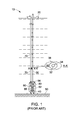
- a traditional offshore oil and gas installation 10, as illustrated in FIG. 1 includes a platform 20 (of any other type of vessel at the water surface) connected via a riser 30 to a wellhead 40 on the seabed 50. It is noted that the elements shown in FIG. 1 are not drawn to scale and no dimensions should be inferred from relative sizes and distances illustrated in FIG. 1 .
- a drill string 32 Inside the riser 30, as shown in the cross-section view, there is a drill string 32 at the end of which a drill bit (not shown) is rotated to extend the subsea well through layers below the seabed 50.
- Mud is circulated from a mud tank (not shown) on the drilling platform 20 through the drill string 32 to the drill bit, and returned to the drilling platform 20 through an annular space 34 between the drill string 32 and a casing 36 of the riser 30.
- the mud maintains a hydrostatic pressure to counter-balancing the pressure of fluids coming out of the well and cools the drill bit while also carrying crushed or cut rock to the surface.
- the mud returning from the well is filtered to remove the rock, and recirculated.
- Offshore oil and gas exploration requires many safety well control devices to be put in place during drilling activities to prevent injury to personnel and destruction of equipment.
- the many layers being drilled through may contain trapped fluids or gases at different pressures.
- the pressure in the wellbore is generally adjusted to at least balance the formation pressure.
- BOPs Blowout preventers
- BOPs are one type of well control device that is often used to close, isolate, and seal a wellbore during a high pressure event or kick. Blowout preventers are typically installed at the surface or on the sea floor in deep water drilling arrangements so that kicks may be adequately controlled and "circulated out" of the system.
- Blowout preventers operate in a similar manner as large valves that are connected to the wellhead and comprise closure members configured to seal and close the well in order to prevent the release of high-pressure gas or liquids from the well.
- choke and kill lines are used to control the kick by adding denser mud.
- annular blowout preventers are typically located at the top of a blowout preventer stack, with one or two annular preventers positioned above a series of several ram-type preventers.
- BOP blowout preventer
- the BOP stack may include a lower BOP stack 62 attached to the wellhead 40, and a Lower Marine Riser Package (“LMRP") 64, which is attached to a distal end of the riser 30.
- LMRP Lower Marine Riser Package
- a plurality of blowout preventers (BOPs) 66 located in the lower BOP stack 62 or in the LMRP 64 are in an open state during normal operation, but may be closed (i.e., switched to a close state) to interrupt a fluid flow through the riser 30 when a "kick" occurs.
- Electrical cables and/or hydraulic lines 70 transport control signals from the drilling platform 20 to a controller 80, which is located on the BOP stack 60.
- the controller 80 controls the BOPs 66 to be in the open state or in the closed state, according to signals received from the platform 20 via the electrical cables and/or hydraulic lines 70.
- the controller 80 also acquires and sends to the platform 20, information related to the current state (open or closed) of the BOPs.
- controller used here covers the well-known configuration with two redundant pods.
- a mud flow output from the well is measured at the surface of the water by sensing device including a float in a mud tank.
- the mud flow input into the well may be adjusted to maintain a pressure at the bottom of the well within a targeted range or around a desired value, or to compensate for kicks and fluid losses.
- blowout preventer valves internal and external to the drill pipe
- heavier drilling mud is pumped down the well bore through kill lines, while a choke line is used to control the flow.
- the choke and kill lines are closed, the blowout preventers are opened and drilling is resumed.
- the drilling must be stopped, in part due to the lack of a rotating wellhead.
- Another problem with the existing methods and devices is the relative long time (e.g., tens of minutes) between a moment when a disturbance of the mud flow occurs at the bottom of the well and when a change of the mud flow is measured at the surface. Even if information indicating a potential disturbance of the mud flow is received from the controller 80 faster, a relative long time passes between when an input mud flow is changed and when this change has a counter-balancing impact at the bottom of the well.
- the controller 80 Even if information indicating a potential disturbance of the mud flow is received from the controller 80 faster, a relative long time passes between when an input mud flow is changed and when this change has a counter-balancing impact at the bottom of the well.
- an influx control system that allows for the continuation of drilling activities during the presence of a substantially higher pressure than that of the wellbore. More particularly, there exists a need for an influx control system that eliminates the need to stop drilling during the presence of a potential blowout condition and during regulation of the mud flow to prevent a blowout from occurring. In addition, there exists a need for an influx control system that allows for sensing of the presence of a substantially higher pressure in a manner that allows for a reduction in response time than current technologies.
- an apparatus useable in an offshore drilling installation close to the seabed for controlling well influx within a wellbore including a centralizer and flow constrictor assembly, a sensor, and a controller.
- the centralizer and flow constrictor assembly is configured to centralize a drill string within a drill riser and regulate a return mud flow.
- the sensor is located close to the centralizer and flow constrictor assembly and configured to acquire values of at least one parameter related to the return mud flow.
- the controller is coupled to the centralizer and flow constrictor assembly and the sensor. The controller is configured to control the centralizer and flow constrictor assembly to achieve a value of a control parameter close to a predetermined value, based on the values acquired by the sensor.
- an apparatus useable in an offshore drilling installation close to the seabed for controlling well influx within a wellbore including a drill riser, a centralizer and flow constrictor assembly, a sensor and a controller.
- the drill riser including a cavity extending from an annular space through which a return mud flow passes.
- the annular space surrounding a drill string through which mud flows towards a top of the well.
- the centralizer and flow constrictor assembly comprising a centralizer component configured to centralize the drill string within the drill riser and a flow constrictor component configured to regulate the return mud flow.
- the sensor is located close to the seabed and configured to acquire values of at least one parameter related to the return mud flow.
- the controller is coupled to the centralizer and flow constrictor assembly and the sensor.
- the controller is configured to control the centralizer and flow constrictor assembly to achieve a value of a control parameter close to a predetermined value, based on the values acquired by the sensor.
- an apparatus useable in an offshore drilling installation close to the seabed for controlling well influx within a wellbore including a drill riser, a centralizer and flow constrictor assembly, a sensor and a controller.
- the drill riser including a cavity extending from an annular space through which a return mud flow passes.
- the annular space surrounding a drill string through which mud flows towards a top of the well.
- the centralizer and flow constrictor assembly including a first centralizer component, a spaced apart second centralizer component and a flow constrictor component.
- the sensor being disposed between the first and second centralizer components.
- the flow constrictor component including a throttle plate disposed on an uppermost surface of the second centralizer component and including an opening therein for the return mud flow.
- the throttle plate operable to regulate the return mud flow.
- the centralizer and flow constrictor assembly further including a flexible bearing and a ram plate.
- the flexible bearing including a bearing surface configured to seal about the drill string while allowing rotation of the drill string.
- the ram plate having an opening therein for the return mud flow.
- the sensor is located close to the seabed and configured to acquire values of at least one parameter related to the return mud flow.
- the controller is coupled to the centralizer and flow constrictor assembly and the sensor. The controller is configured to control the centralizer and flow constrictor assembly to achieve a value of a control parameter close to a predetermined value, based on the values acquired by the sensor.
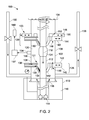
- FIGs. 2-5 illustrate schematic diagrams of an exemplary embodiment of an apparatus 100 useable in an offshore drilling installation and more particularly a seabed well influx control system 102 for controlling well influx within a wellbore.
- FIG. 3 is a partial cut-away view of a centralizer and flow constrictor assembly of the apparatus 100.
- FIG. 4 is a schematic diagram illustrating a plurality of lubrication feeds in the apparatus 100 and
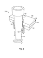
- FIG. 5 is a schematic diagram illustrating a portion of a flexible element bearing of the apparatus 100, all according to an exemplary embodiment.
- the apparatus 100 includes a centralizer component 101 and a flow constrictor component 103 and is configured to automatically sense and regulate a returning mud flow in a mud loop as a means for detecting an increase in pressure and preventing a potential blowout condition.
- the apparatus includes a platform (not shown) or any other type of vessel at the water surface 104 connected via a riser 106 to a wellhead 108 on the seabed 110. It is noted that the elements shown in the Figures are not drawn to scale and no dimensions should be inferred from relative sizes and distances illustrated in the Figures.
- a drill string 112 Inside the riser 106, there is disposed a drill string 112 at the end of which a drill bit 114 is rotated to extend the subsea well through layers 116 below the seabed 110. Mud, indicated by arrows 118, is circulated in a mud loop, from a mud tank (not shown) on the drilling platform through the drill string 112 to the drill bit 114, and returned to the drilling platform through an annular space 120 between the drill string 112 and a casing 122 of the riser 106.
- the seabed well influx control system 102 includes a plurality of spaced apart centralizer and flow constrictor assemblies 128 positioned proximate the drill string 112 and located close to the seabed 110.
- the plurality of centralizer and flow constrictor assemblies 128 are configured in a vertical spaced apart relationship about the drill string 112 and in a manner to center and hold the drill string 112 within the casing 122 and provide for constriction of the mud flow therethrough, as desired.
- Each of the centralizer and flow constrictor assemblies 128, and more particularly the centralizer component 101 includes a flexible element bearing 130 integrally formed therewith a blowout preventer (BOP) 140.
- BOP blowout preventer
- each of the flexible element bearings 130 includes a flexible face 132 and a plurality of high pressure lubrication feeds, or orifices, 134 formed therethrough.
- each of the plurality of flexible element bearings 130 is formed of a plurality of segments 131, each of which may include steel inserts, such as steel springs, wedges, or as illustrated in FIG. 5 , a leaf spring 133.
- Each of the plurality of flexible element bearings are formed of a flexible material, such as elastomer, rubber, or the like.
- the flexible element bearing 130 is capable of flexing to provide for insertion therethrough of a drill string tool joint 124.
- the flexible face 132 of each flexible bearing 130 is configured to provide sealing between the drill string 112 and the flexible face 134 during drilling operations.
- the plurality of high pressure lubrication feeds 134 are configured in fluidic communication with a plurality of high pressure fluid feeds 136 formed in each of the blow out preventers 140, and more particularly ram plates (described presently).
- Lubrication may be provided by pumping drilling mud or an external fluid at pressures above that of the wellbore to ensure bias leakage of mud/fluid into the well, thus sealing any mud 118 to travel in an upward direction and around the drill string 112 due to kick.
- the high pressure lubrication feeds 134, 136 are configured to supply a drilling fluid which acts as a lubricant between the drill string 112 and the flexible face 132 during the drilling operation, as well as between the flexible element bearing 130 and the drill string tool joint 124 during drilling operations.
- each of the plurality of flexible element bearings 130 is integrally formed with one of the plurality of blowout preventers (BOPs) 140.
- BOPs blowout preventers
- Each of the plurality of blow out preventers 140 is configured as split ram blow out preventers, such as those commonly known in the art and additionally serves to centralize and hold the drill string 112 centered within the riser 106.
- a first ram plate 142 is positioned proximate the seabed 110 and a second ram plate 144 is positioned in a spaced apart relationship from the first ram plate 142, and above the first ram plate 142, relative to the seabed 110.
- Each of the first and second ram plates 142, 144 include an opening 146 formed therein in a manner providing for the flow of mud 118, initially pumped in a downward direction through the drill string 112, to flow in an opposed, upward direction and back toward the water surface 104 through the riser 106 via the openings 146.
- At least an upper centralizer and flow restrictor assembly 128, and more particularly the flow constrictor component 103 includes a throttle plate 148.
- the throttle plate 148 is disposed on an uppermost surface 150 of the second ram plate 144, and having an opening 152 provided therein.
- the throttle plate 148 is operable to provide adjustment and/or constriction in the flow of mud 118 as it is returned through the riser 106 toward the water surface 104.
- a second redundant throttle plate may be positioned on an uppermost surface of the first ram plate 142 and operable in case of failure of the primary throttle plate 148.
- the throttle plate 148 is configured as a valve and capable of regulating the returning mud flow 118, by modifying (increasing or decreasing) a surface of an annular opening 152 formed therein and in operable alignment/misalignment with the opening 146 formed in the second ram plate 144 to increase or decrease in size.
- the throttle plate 148 is in an open state, with openings 152 in alignment with openings 146, during normal operation, but may be closed (i.e., switched to a closed state) with openings 152 in misalignment, or at least partial misalignment, with openings 146, to interrupt a fluid flow through the riser 106 when under a high pressure event, such as when a "kick" occurs.
- Throttling the flow using throttle plate is just one way to control flow.
- Other valve types may be designed/incorporated in to the RAM plates to allow control of flow.
- a sensor 154 is located on the riser 106, and more particularly, on an outer surface 156 of the casing 122, disposed between the first ram plate 122 and the second ram plate 124.
- the sensor 154 is configured to acquire information related to a mud flow returning from the bottom of the well.
- a distance from a source of the mud (i.e., a mud tank of a platform at the water surface) to the seabed may be thousands of feet. Therefore it may take a significant time interval (minutes or even tens of minutes) until a change of a parameter (e.g., pressure or flow rate) related to the mud flow becomes measurable at the surface.
- Placement of the sensor between the first ram plate 122 and the second ram plate 124 minimizes errors in reading flow rate which arise due to the orbiting of the drill string 112 and minimizes response time.
- the throttle plate 148 is actuated via actuators 149 (hydraulic or electrical) after receiving commands from a controller 157 that has received a signal from the sensor 154.
- Sensor 154 primarily measures flow velocity as a means of detecting kick. Change in velocity above a certain percentage of normal velocity is considered a kick which starts the control process.
- the controller 156 is configured to automatically control the throttle plate 148 based on the values received by the sensor 154, in order to regulate the returning mud flow towards achieving a value of a control parameter close to a predetermined value. Automatically controlling means that no signal from the surface is expected or required. However, this mode of operating does not exclude a connection between the control loop and an external operator that may enable occasional manual operation or receiving new parameters, such as, the predetermined value.
- the sensor 154 may include a pressure sensor and the control parameter may be the measured pressure or another parameter that may be calculated based on the measured pressure.
- the controller 156 controls the throttle plate 148 to slideably misalign the opening 152 relative to the opening 146 thereby decreasing the flow and, thus, the dynamic pressure if the pressure is larger than a set value, such as when under a high pressure event.
- the controller 156 controls the throttle plate 148 to slideably align the opening 152 relative to the opening 146 thereby increasing the flow and, thus, the dynamic pressure if the pressure is smaller than the set value.
- the controlled pressure may be the pressure below the throttle plate 148 or near a bottom of the well.
- the senor 154 may also include a flow meter measuring the mud flow therethrough, and the control parameter may be the mud flow itself.
- the controller 156 then controls the throttle plate 148 to close off the opening 152 if the mud flow is larger than a set value, or to maintain the opening 152 in an open position if the mud flow is smaller than the set value.
- the controller 156 may receive information about both the amount of returning mud flow from a mud flow meter and pressure from a pressure sensor.
- C/K feed-thrus or lines
- the C/K feed-thrus 158, 160 are operational to provide an input of heavier drilling mud down the well bore through the kill feed-thru 160, while the choke feed-thru 158 is used to control the flow during drilling and high pressure events.
- FIG. 6 illustrated is a schematic diagram of an exemplary embodiment of an apparatus 200 useable in an offshore drilling installation and more particularly, a seabed well influx control system 202.
- a seabed well influx control system 202 As previously indicated, it should be understood that like numerals are used to refer to like and corresponding parts of the various drawings.
- the apparatus 200 includes a single centralizer and flow constrictor assembly 228, and more particularly a single centralizer component 101 and a single flow constrictor component 103.
- the apparatus includes a riser 106 to connect a platform, or the like (not shown), to a wellhead 108 on the seabed 110. Inside the riser 106, is the drill string 112 at the end of which is the drill bit 114 to extend the subsea well through layers 116 below the seabed 110.
- the seabed well influx control system 202 includes the single centralizer and flow constrictor assembly 228 positioned proximate the drill string 112 and located close to the seabed 110.
- the centralizer and flow constrictor assembly 228 is configured about the drill string 112 and in a manner to center and hold the drill string 112 within the casing 122 and provide for constriction of the flow therethrough.
- the centralizer and flow constrictor assembly 228 includes a flexible element bearing 130 integrally formed therewith a blowout preventer (BOP) 140 as previously described with regard to FIG. 2-5 .
- the flexible element bearing 130 includes a flexible face 132 and a plurality of high pressure lubrication feeds, or orifices, 134 formed therethrough.
- the flexible element 130 is configured to flex for insertion and lubrication of the drill string tool joint 124.
- the flexible element bearing 130 provides sealing between the drill string 112 and the flexible face 132 during drilling operation.
- the plurality of high pressure lubrication feeds 134 are configured in fluidic communication with a plurality of high pressure fluid feeds 136 formed in the ram plate (described presently).
- the blow out preventer 140 is configured as split ram blow out preventer and serves to centralize and hold the drill string 112 centered within the riser 106.
- the drill string 112 is sufficiently maintained in a centralized position with the use of a single centralizer component 101. Illustrated in FIG. 6 is a ram plate 242 positioned proximate the seabed 110.
- the ram plate 242 does not include an opening formed therein in a manner providing for the flow of mud 118 therethrough as it is returned to the water surface 104.
- the flow of mud 118 is initially pumped in a downward direction through the drill string 112, to flow in an opposed, upward direction and back toward the water surface 104 through a bypass assembly 244 and into the riser 106.
- the bypass assembly 244 includes a conduit 246 in fluidic communication with the riser 106 at a conduit inlet 248 and a conduit outlet 250.
- the conduit 246 includes a throttle assembly 252 disposed therein.
- the throttle assembly 252 includes a plurality of throttle plates 148 each having an opening 152 provided therein.
- the throttle plates 148 are operable to provide adjustment and/or constriction in the flow of mud 118 as it is returned through the riser 106 toward the water surface 104 via the conduit 246, and more particularly from a first side 255 of the single centralizer component 10) to a second side 257 of the single centralizer component 10.
- At least one of the throttle plates 252 is moveable relative to the additional throttle plate 148 to align/misalign the openings 152 formed therein, respectively.
- the throttle assembly 252 is in an open state during normal operation, but may be closed (i.e., switched to a closed state) to interrupt a fluid flow through the riser 106 when under a high pressure event, such as when a "kick" occurs.
- a sensor 154 is located on the conduit 246, and more particularly, on an outer surface 254 of the conduit 246.
- the sensor 154 is configured similar to that described in FIG. 2 . Placement of the sensor on the bypass assembly 244, and more particularly the conduit 246, provides for a decrease in sensitivity of the sensor 154 to movement or vibration due to the drill string 112 orbiting and minimizes throttle constriction response time.
- the throttle plates 148 are configured as a valve and capable of regulating the returning mud flow 118, by modifying (increasing or decreasing) a surface of the annular openings 152 formed therein and operable by alignment/misalignment of the openings 152 to increase or decrease in size. It is anticipated that in an alternate embodiment, the throttle plates 148 may be replaced by any type of valve operational to constrict the flow therethrough the conduit 246, such as a gate valve, or the like. In an embodiment, the throttle plates 148 are controlled by a controller 156 connected to the sensor 154 and operational as previously described.
- the controller 156 controls the throttle plates 148 to slideably misalign the openings 152 thereby decreasing the flow and, thus, the dynamic pressure if the pressure is larger than a set value.
- the controller 156 controls the throttle plates 148 to slideably align the openings 152 thereby increasing the flow and, thus, the dynamic pressure if the pressure is smaller than the set value.
- kill and choke lines 158, 160 respectively, running alongside an exterior of the drilling riser 106, as commonly known in the art.
- FIG. 7 illustrated is an embodiment similar to the embodiment illustrated in FIG. 6 , except in this particular embodiment, disclosed is an apparatus 300 including a single centralizer and flow constrictor assembly 228, and more particularly a single flow constrictor component 103 and a single centralizer component 101, including a one-piece annular head 302 and means for lubrication.
- the apparatus is configured generally similar to the previously described embodiment illustrated in FIG. 6 including a riser 106, a drill string 112, a ram plate 242 and bypass assembly 244.
- the centralizer component 101 includes the one-piece annular bearing 302 having formed therein plurality of high pressure fluid feeds 134 in alignment with a plurality of high pressure feeds 136 formed in the ram plate 140. Additional information on the one-piece annular bearing 302 can be found, for example, in U.S. Publication No. 2008/0023917 (the entire contents of which are incorporated by reference herein). The inclusion of the one-piece annular bearing 302 provides an improved design that serves to improve the stability of the drill string 112 and bearing surfaces during orbiting of the drill string 112.
- the disclosed exemplary embodiments provide apparatuses for well influx control, and more particularly provide for the continuation of drilling operation when a potential well bore kick condition is detected in an offshore installation.
- the control is performed promptly (e.g., less than a tenth of a second between detection and corrective action, as opposed to minutes in the conventional approach) and can be performed frequently (e.g., few times every second).
- At least some of the embodiments result in an increase of safety.
- a response time for return flow variation is significantly reduced without requiring expensive equipment or shut down of the drilling operation.
- the rotating wellhead areis configured as an integral part of the BOP stack and therefore require minimal seals to stop the flow of mud through the annulus.
Landscapes
- Engineering & Computer Science (AREA)
- Life Sciences & Earth Sciences (AREA)
- Geology (AREA)
- Mining & Mineral Resources (AREA)
- Physics & Mathematics (AREA)
- Environmental & Geological Engineering (AREA)
- Fluid Mechanics (AREA)
- General Life Sciences & Earth Sciences (AREA)
- Geochemistry & Mineralogy (AREA)
- Mechanical Engineering (AREA)
- Geophysics (AREA)
- Earth Drilling (AREA)
Applications Claiming Priority (2)
| Application Number | Priority Date | Filing Date | Title |
|---|---|---|---|
| US201161566091P | 2011-12-02 | 2011-12-02 | |
| US13/483,713 US9080427B2 (en) | 2011-12-02 | 2012-05-30 | Seabed well influx control system |
Publications (2)
| Publication Number | Publication Date |
|---|---|
| EP2599951A2 true EP2599951A2 (de) | 2013-06-05 |
| EP2599951A3 EP2599951A3 (de) | 2017-11-22 |
Family
ID=47294690
Family Applications (1)
| Application Number | Title | Priority Date | Filing Date |
|---|---|---|---|
| EP12194194.2A Withdrawn EP2599951A3 (de) | 2011-12-02 | 2012-11-26 | Meeresgrund-Bohrlocheinströmungssteuerungssystem |
Country Status (7)
| Country | Link |
|---|---|
| US (1) | US9080427B2 (de) |
| EP (1) | EP2599951A3 (de) |
| CN (1) | CN103132956B (de) |
| AU (1) | AU2012258322B2 (de) |
| BR (1) | BR102012029886B1 (de) |
| MY (1) | MY161674A (de) |
| SG (1) | SG190554A1 (de) |
Cited By (2)
| Publication number | Priority date | Publication date | Assignee | Title |
|---|---|---|---|---|
| WO2013184866A3 (en) * | 2012-06-07 | 2014-08-28 | General Electric Company | Flow control system |
| KR20150145554A (ko) * | 2014-06-20 | 2015-12-30 | 대우조선해양 주식회사 | 이중 구배 드릴링 시스템 |
Families Citing this family (9)
| Publication number | Priority date | Publication date | Assignee | Title |
|---|---|---|---|---|
| SG11201601361XA (en) * | 2013-09-24 | 2016-04-28 | Halliburton Energy Services Inc | Reinforced drill pipe seal with floating backup layer |
| US9631442B2 (en) * | 2013-12-19 | 2017-04-25 | Weatherford Technology Holdings, Llc | Heave compensation system for assembling a drill string |
| US9416649B2 (en) * | 2014-01-17 | 2016-08-16 | General Electric Company | Method and system for determination of pipe location in blowout preventers |
| US10648315B2 (en) * | 2016-06-29 | 2020-05-12 | Schlumberger Technology Corporation | Automated well pressure control and gas handling system and method |
| US10450815B2 (en) * | 2016-11-21 | 2019-10-22 | Cameron International Corporation | Flow restrictor system |
| EP3555416A4 (de) * | 2016-12-13 | 2020-07-29 | Services Petroliers Schlumberger | Ausgerichtete scheibendrossel für verwaltetes druckbohren |
| EP3559396A4 (de) | 2016-12-22 | 2020-07-29 | Services Petroliers Schlumberger | Ringförmige verstellbare rohrrammenbegrenzung zur verwalteten druckbohrung mit austauschbaren rammen |
| MX2019007618A (es) | 2016-12-22 | 2019-12-05 | Schlumberger Technology Bv | Restricción anular por etapas para perforación a presión controlada. |
| CN109611035B (zh) * | 2018-11-26 | 2023-11-10 | 中国石油大学(北京) | 导管承载力加强装置及其使用方法 |
Citations (7)
| Publication number | Priority date | Publication date | Assignee | Title |
|---|---|---|---|---|
| US2609836A (en) * | 1946-08-16 | 1952-09-09 | Hydril Corp | Control head and blow-out preventer |
| US5662181A (en) * | 1992-09-30 | 1997-09-02 | Williams; John R. | Rotating blowout preventer |
| US20080023917A1 (en) | 2006-07-28 | 2008-01-31 | Hydril Company Lp | Seal for blowout preventer with selective debonding |
| US7395878B2 (en) | 2003-08-19 | 2008-07-08 | At-Balance Americas, Llc | Drilling system and method |
| US7562723B2 (en) | 2006-01-05 | 2009-07-21 | At Balance Americas, Llc | Method for determining formation fluid entry into or drilling fluid loss from a borehole using a dynamic annular pressure control system |
| US7650950B2 (en) | 2000-12-18 | 2010-01-26 | Secure Drilling International, L.P. | Drilling system and method |
| US20100252328A1 (en) * | 2007-08-27 | 2010-10-07 | Williams John R | Tapered surface bearing assembly and well drilling equipment comprising same |
Family Cites Families (21)
| Publication number | Priority date | Publication date | Assignee | Title |
|---|---|---|---|---|
| US4273212A (en) * | 1979-01-26 | 1981-06-16 | Westinghouse Electric Corp. | Oil and gas well kick detector |
| US4640372A (en) * | 1985-11-25 | 1987-02-03 | Davis Haggai D | Diverter including apparatus for breaking up large pieces of formation carried to the surface by the drilling mud |
| CN1010422B (zh) * | 1987-08-03 | 1990-11-14 | 潘盖伊公司 | 采用多导管管材的钻杆和套管 |
| US5006845A (en) * | 1989-06-13 | 1991-04-09 | Honeywell Inc. | Gas kick detector |
| US5163029A (en) * | 1991-02-08 | 1992-11-10 | Teleco Oilfield Services Inc. | Method for detection of influx gas into a marine riser of an oil or gas rig |
| US5588491A (en) | 1995-08-10 | 1996-12-31 | Varco Shaffer, Inc. | Rotating blowout preventer and method |
| US6904982B2 (en) | 1998-03-27 | 2005-06-14 | Hydril Company | Subsea mud pump and control system |
| NO308043B1 (no) * | 1998-05-26 | 2000-07-10 | Agr Subsea As | Anordning for å fjerne borekaks og gasser i forbindelse med boring |
| US7270185B2 (en) * | 1998-07-15 | 2007-09-18 | Baker Hughes Incorporated | Drilling system and method for controlling equivalent circulating density during drilling of wellbores |
| EG22117A (en) * | 1999-06-03 | 2002-08-30 | Exxonmobil Upstream Res Co | Method and apparatus for controlling pressure and detecting well control problems during drilling of an offshore well using a gas-lifted riser |
| US6571873B2 (en) * | 2001-02-23 | 2003-06-03 | Exxonmobil Upstream Research Company | Method for controlling bottom-hole pressure during dual-gradient drilling |
| CA2461639C (en) * | 2001-09-10 | 2013-08-06 | Ocean Riser Systems As | Arrangement and method for regulating bottom hole pressures when drilling deepwater offshore wells |
| US6755261B2 (en) * | 2002-03-07 | 2004-06-29 | Varco I/P, Inc. | Method and system for controlling well fluid circulation rate |
| BR122017010168B1 (pt) | 2005-10-20 | 2018-06-26 | Transocean Sedco Forex Ventures Ltd. | Método para controlar pressão e/ou densidade de um fluido de perfuração |
| NO326492B1 (no) * | 2007-04-27 | 2008-12-15 | Siem Wis As | Tetningsarrangement for dynamisk tetning rundt en borestreng |
| US8122964B2 (en) | 2008-05-29 | 2012-02-28 | Hydril Usa Manufacturing Llc | Subsea stack alignment method |
| US8322432B2 (en) * | 2009-01-15 | 2012-12-04 | Weatherford/Lamb, Inc. | Subsea internal riser rotating control device system and method |
| US8567525B2 (en) * | 2009-08-19 | 2013-10-29 | Smith International, Inc. | Method for determining fluid control events in a borehole using a dynamic annular pressure control system |
| US8403059B2 (en) * | 2010-05-12 | 2013-03-26 | Sunstone Technologies, Llc | External jet pump for dual gradient drilling |
| EP2659082A4 (de) * | 2010-12-29 | 2017-11-08 | Halliburton Energy Services, Inc. | Unterwasser-druckregelungssystem |
| EP2764198B1 (de) * | 2011-10-07 | 2023-05-31 | Weatherford Technology Holdings, LLC | Dichtungsanordnungen in rotierenden unterwasser-steuervorrichtungen |
-
2012
- 2012-05-30 US US13/483,713 patent/US9080427B2/en not_active Expired - Fee Related
- 2012-11-09 MY MYPI2012004901A patent/MY161674A/en unknown
- 2012-11-21 AU AU2012258322A patent/AU2012258322B2/en not_active Ceased
- 2012-11-23 BR BR102012029886-4A patent/BR102012029886B1/pt not_active IP Right Cessation
- 2012-11-26 EP EP12194194.2A patent/EP2599951A3/de not_active Withdrawn
- 2012-11-27 SG SG2012087193A patent/SG190554A1/en unknown
- 2012-11-30 CN CN201210501259.5A patent/CN103132956B/zh not_active Expired - Fee Related
Patent Citations (7)
| Publication number | Priority date | Publication date | Assignee | Title |
|---|---|---|---|---|
| US2609836A (en) * | 1946-08-16 | 1952-09-09 | Hydril Corp | Control head and blow-out preventer |
| US5662181A (en) * | 1992-09-30 | 1997-09-02 | Williams; John R. | Rotating blowout preventer |
| US7650950B2 (en) | 2000-12-18 | 2010-01-26 | Secure Drilling International, L.P. | Drilling system and method |
| US7395878B2 (en) | 2003-08-19 | 2008-07-08 | At-Balance Americas, Llc | Drilling system and method |
| US7562723B2 (en) | 2006-01-05 | 2009-07-21 | At Balance Americas, Llc | Method for determining formation fluid entry into or drilling fluid loss from a borehole using a dynamic annular pressure control system |
| US20080023917A1 (en) | 2006-07-28 | 2008-01-31 | Hydril Company Lp | Seal for blowout preventer with selective debonding |
| US20100252328A1 (en) * | 2007-08-27 | 2010-10-07 | Williams John R | Tapered surface bearing assembly and well drilling equipment comprising same |
Cited By (2)
| Publication number | Priority date | Publication date | Assignee | Title |
|---|---|---|---|---|
| WO2013184866A3 (en) * | 2012-06-07 | 2014-08-28 | General Electric Company | Flow control system |
| KR20150145554A (ko) * | 2014-06-20 | 2015-12-30 | 대우조선해양 주식회사 | 이중 구배 드릴링 시스템 |
Also Published As
| Publication number | Publication date |
|---|---|
| CN103132956A (zh) | 2013-06-05 |
| BR102012029886A2 (pt) | 2014-06-10 |
| SG190554A1 (en) | 2013-06-28 |
| AU2012258322A1 (en) | 2013-06-20 |
| US9080427B2 (en) | 2015-07-14 |
| EP2599951A3 (de) | 2017-11-22 |
| BR102012029886B1 (pt) | 2020-09-24 |
| MY161674A (en) | 2017-05-15 |
| BR102012029886A8 (pt) | 2018-05-22 |
| AU2012258322B2 (en) | 2016-11-24 |
| CN103132956B (zh) | 2017-04-12 |
| US20130140034A1 (en) | 2013-06-06 |
Similar Documents
| Publication | Publication Date | Title |
|---|---|---|
| US9080427B2 (en) | Seabed well influx control system | |
| US9016381B2 (en) | Mudline managed pressure drilling and enhanced influx detection | |
| US11306550B2 (en) | Seal condition monitoring | |
| US6470975B1 (en) | Internal riser rotating control head | |
| US9476271B2 (en) | Flow control system | |
| US20240044216A1 (en) | Multi-mode pumped riser arrangement and methods | |
| US11060367B2 (en) | Rotating choke assembly | |
| Johnson et al. | Real Time Condition Monitoring of the Wellbore Seal through Hydraulic Fluid Analysis Using an Active Wellbore Sealing System during Managed Pressure Drilling | |
| US12352112B2 (en) | Multi-mode pumped riser arrangement and methods | |
| Potter | Advent of innovative adaptive drilling methods | |
| CA3084979C (en) | Seal condition monitoring |
Legal Events
| Date | Code | Title | Description |
|---|---|---|---|
| PUAI | Public reference made under article 153(3) epc to a published international application that has entered the european phase |
Free format text: ORIGINAL CODE: 0009012 |
|
| AK | Designated contracting states |
Kind code of ref document: A2 Designated state(s): AL AT BE BG CH CY CZ DE DK EE ES FI FR GB GR HR HU IE IS IT LI LT LU LV MC MK MT NL NO PL PT RO RS SE SI SK SM TR |
|
| AX | Request for extension of the european patent |
Extension state: BA ME |
|
| PUAL | Search report despatched |
Free format text: ORIGINAL CODE: 0009013 |
|
| AK | Designated contracting states |
Kind code of ref document: A3 Designated state(s): AL AT BE BG CH CY CZ DE DK EE ES FI FR GB GR HR HU IE IS IT LI LT LU LV MC MK MT NL NO PL PT RO RS SE SI SK SM TR |
|
| AX | Request for extension of the european patent |
Extension state: BA ME |
|
| RIC1 | Information provided on ipc code assigned before grant |
Ipc: E21B 33/08 20060101ALI20171013BHEP Ipc: E21B 21/08 20060101AFI20171013BHEP Ipc: E21B 17/10 20060101ALI20171013BHEP Ipc: E21B 34/16 20060101ALI20171013BHEP Ipc: E21B 33/064 20060101ALI20171013BHEP Ipc: E21B 34/00 20060101ALI20171013BHEP |
|
| STAA | Information on the status of an ep patent application or granted ep patent |
Free format text: STATUS: REQUEST FOR EXAMINATION WAS MADE |
|
| 17P | Request for examination filed |
Effective date: 20180522 |
|
| RBV | Designated contracting states (corrected) |
Designated state(s): AL AT BE BG CH CY CZ DE DK EE ES FI FR GB GR HR HU IE IS IT LI LT LU LV MC MK MT NL NO PL PT RO RS SE SI SK SM TR |
|
| STAA | Information on the status of an ep patent application or granted ep patent |
Free format text: STATUS: EXAMINATION IS IN PROGRESS |
|
| 17Q | First examination report despatched |
Effective date: 20181120 |
|
| RAP1 | Party data changed (applicant data changed or rights of an application transferred) |
Owner name: BAKER HUGHES, A GE COMPANY, LLC |
|
| RAP3 | Party data changed (applicant data changed or rights of an application transferred) |
Owner name: BAKER HUGHES HOLDINGS LLC |
|
| RAP1 | Party data changed (applicant data changed or rights of an application transferred) |
Owner name: HYDRIL USA DISTRIBUTION LLC |
|
| STAA | Information on the status of an ep patent application or granted ep patent |
Free format text: STATUS: THE APPLICATION IS DEEMED TO BE WITHDRAWN |
|
| 18D | Application deemed to be withdrawn |
Effective date: 20220601 |