EP2599954A2 - Packer de sonde et son procédé d'utilisation - Google Patents
Packer de sonde et son procédé d'utilisation Download PDFInfo
- Publication number
- EP2599954A2 EP2599954A2 EP11290552.6A EP11290552A EP2599954A2 EP 2599954 A2 EP2599954 A2 EP 2599954A2 EP 11290552 A EP11290552 A EP 11290552A EP 2599954 A2 EP2599954 A2 EP 2599954A2
- Authority
- EP
- European Patent Office
- Prior art keywords
- packer
- downhole tool
- probe
- wellbore
- base
- Prior art date
- Legal status (The legal status is an assumption and is not a legal conclusion. Google has not performed a legal analysis and makes no representation as to the accuracy of the status listed.)
- Withdrawn
Links
Images




Classifications
-
- E—FIXED CONSTRUCTIONS
- E21—EARTH OR ROCK DRILLING; MINING
- E21B—EARTH OR ROCK DRILLING; OBTAINING OIL, GAS, WATER, SOLUBLE OR MELTABLE MATERIALS OR A SLURRY OF MINERALS FROM WELLS
- E21B49/00—Testing the nature of borehole walls; Formation testing; Methods or apparatus for obtaining samples of soil or well fluids, specially adapted to earth drilling or wells
- E21B49/08—Obtaining fluid samples or testing fluids, in boreholes or wells
- E21B49/10—Obtaining fluid samples or testing fluids, in boreholes or wells using side-wall fluid samplers or testers
-
- E—FIXED CONSTRUCTIONS
- E21—EARTH OR ROCK DRILLING; MINING
- E21B—EARTH OR ROCK DRILLING; OBTAINING OIL, GAS, WATER, SOLUBLE OR MELTABLE MATERIALS OR A SLURRY OF MINERALS FROM WELLS
- E21B33/00—Sealing or packing boreholes or wells
- E21B33/10—Sealing or packing boreholes or wells in the borehole
- E21B33/12—Packers; Plugs
- E21B33/1208—Packers; Plugs characterised by the construction of the sealing or packing means
- E21B33/1216—Anti-extrusion means, e.g. means to prevent cold flow of rubber packing
Definitions
- This present disclosure relates generally to techniques for performing formation evaluation. More specifically, the present disclosure relates to techniques, such as packers and/or probes, for sealing with a wall of a wellbore.
- Downhole tools may be deployed into the earth to locate and gather valuable hydrocarbons.
- Drilling tools may be advanced from a surface rig into the earth to form a wellbore.
- the drilling tool may include a series of drill pipes with a drill bit at an end thereof rotationally advanced into the earth.
- a drilling mud may be pumped through the drilling tool and out of the drill bit to cool the drilling tool, to carry away cuttings generated during drilling, and to line the wellbore.
- Formation evaluation tools may be deployed into the wellbore, for example, to investigate downhole formations and/or to determine the viability of retrieving hydrocarbons.
- the formation evaluation tools may be part of the drilling tool.
- the downhole tools may be removed from the wellbore so that a separate formation evaluation tool may be deployed into the wellbore to perform various operations, such as measuring, testing, sampling, or other formation evaluation operations.
- Downhole tools may be provided with various formation evaluation devices (e.g., gauges, sensors, probes, fluid circuits, etc.) for performing formation evaluation. Some formation evaluation operations may involve drawing fluid into the downhole tool for testing and/or for collection in sample chambers.
- the downhole tool may be provided with one or more probes for forming a seal with a wall of the wellbore and drawing fluid therein. Examples of probes are described in US Patent Nos. 7793713 , 7585786 , 7458419 and 7114385 .
- the probe may be provided with a packer for establishing the seal, and with an inlet for drawing fluid into the downhole tool. Examples of packers are described in US Patent/Application Nos. 7121338 , 2007/0151727 and 2010/0155053 .
- the techniques herein relate to a probe for forming a seal between a downhole tool and a wall of the wellbore.
- the probe has a packer that is supported as it is pressed against the wall of the wellbore.
- the packer may be provided with support features, such as a raised packer support for internal support thereof and/or a packer stopper for external support about a perimeter thereof.
- the disclosure relates to a downhole tool including a probe for forming a seal between the downhole tool and a wall of a wellbore penetrating a subterranean formation.
- the downhole tool may include a probe inlet extending from the downhole tool for fluid communication with the subterranean formation, a base positionable about the downhole tool (the base having a raised packer support ring extending therefrom), and a packer for forming the seal with the wall of the wellbore.
- the packer may be positionable on the base and has an inlet channel extending therethrough for receiving the probe inlet.
- the packer may have a support channel extending a distance therein for receiving the raised packer support whereby the packer is supported as it is compressed against the wall of the wellbore.
- the packer may have a donut shaped body.
- the support channel may extend into the packer from an outer perimeter downhole tool and from a base surface of the packer.
- the packer support ring may be a plate operatively connectable to the base or a downhole tool integral with the base.
- the packer support ring may have a raised lip on an inner diameter thereof, and the raised lip an S-shaped cross-section.
- the inlet channel may have an outwardly tapered outer portion adjacent an outer surface of the packer.
- the inlet channel may have an inwardly tapered inner portion adjacent a base surface of the packer.
- the probe inlet may be in fluid communication with a fluid circuit of the downhole tool.
- the base may be selectively extendable from a housing of the downhole tool.
- the downhole tool may be a wireline tool, a drilling tool, a coiled tubing tool, a completions tool, a testing tool, and/or a production tool.
- the disclosure relates to a method of forming a seal between a downhole tool and a wall of a wellbore penetrating a subterranean formation.
- the method involves providing the downhole tool with a probe.
- the probe includes a probe inlet extending from the downhole tool for fluid communication with the subterranean formation, a base positionable about the downhole tool (the base having a raised packer support ring extending therefrom), and a packer for forming the seal with the wall of the wellbore.
- the packer is positionable on the base and has an inlet channel extending therethrough for receiving the probe inlet.
- the packer has a support channel extending a distance therein for receiving the raised packer support whereby the packer is supported as it is compressed against the wall of the wellbore.
- the method further involves positioning the probe against the wall of the wellbore, and forming the seal between the packer and the wall of the wellbore by supporting the packer with the raised packer support ring while compressing the packer against the wall of the wellbore.
- the method may also involve establishing fluid communication between the subterranean formation and the probe inlet, drawing fluid from the subterranean formation into the downhole tool, securing the packer to the base, and/or forming a seal between the packer and the inlet.
- the invention may relate to a downhole tool including a probe for forming a seal between the downhole tool and a wall of a wellbore penetrating a subterranean formation.
- the downhole tool including a probe inlet extending from the downhole tool for fluid communication with the subterranean formation, a base positionable about the downhole tool, a packer for forming the seal with the wall of the wellbore (the packer positionable on the base and having an inlet channel extending therethrough for receiving the probe inlet), and a packer stopper for supporting the packer.
- the packer stopper extends from the base about a perimeter of the packer with an expansion gap defined therebetween whereby the packer is supported as it is compressed against the wall of the wellbore.
- the packer stopper may have a ring shaped body with one of a triangular cross-section, or a trapezoidal cross-section.
- the perimeter of the probe may be tapered away from the packer stopper and an inner diameter of the packer stopper is flat.
- the perimeter of the probe may be flat and an inner diameter of the packer stopper may be tapered away from the perimeter of the packer.
- the probe inlet may be in fluid communication with a fluid circuit of the downhole tool.
- the base may be selectively extendable from a housing of the downhole tool.
- the downhole tool may be a wireline tool, a drilling tool, a coiled tubing tool, a completions tool, a testing tool, and/or a production tool.
- the disclosure relates to a method of forming a seal between a downhole tool and a wall of a wellbore penetrating a subterranean formation.
- the method involves providing the downhole tool with a probe.
- the probe includes a probe inlet extending from the downhole tool for fluid communication with the subterranean formation, a base positionable about the downhole tool, a packer for forming the seal with the wall of the wellbore (the packer positionable on the base and having an inlet channel extending therethrough for receiving the probe inlet), and a packer stopper for supporting the packer.
- the packer stopper extends from the base about a perimeter of the packer with an expansion gap is defined therebetween whereby the packer is supported as it is compressed against the wall of the wellbore.
- the method involves positioning the probe against the wall of the wellbore, and forming the seal between the packer and the wall of the wellbore by supporting the packer with the packer stopper while compressing the packer against the wall of the wellbore.
- the method may also involve forming the seal involves permitting the packer to expand into the expansion gap, establishing fluid communication between the subterranean formation and the probe inlet, drawing fluid from the subterranean formation into the downhole tool, securing the packer to the base, forming a seal between the packer and the probe inlet.
- the techniques herein relate to a probe and/or packer for sealing a downhole tool with a wellbore wall.
- the packer may be provided with a support extending therein and/or a packer stopper along a perimeter thereof to support the packer as the packer is pressed against the wellbore wall.
- the packer may also be configured to eliminate interference with an inlet of the probe extending through the packer.
- the probe and/or packer may be configured to achieve one or more of the following, among others: reduced wear, reduced damage, reduced failure, reduced leakage, enhanced sealing, etc.
- Figure 1 depicts a wellsite 100 having a rig 102 with a downhole tool 104 deployed into a wellbore 106 therebelow.
- the wellsite 100 is depicted as land-based, but could be offshore.
- the downhole tool 104 is depicted as a wireline tool, but could be any downhole tool (e.g., drilling, coiled tubing, completions, testing, production or other downhole tool).
- the downhole tool 104 is positionable in the wellbore 106 for drawing formation fluid 108 from a surrounding formation 110.
- the downhole tool 104 may have a probe 112 positionable against a wall 114 of the wellbore 106 for establishing fluid communication with the formation 110.
- a cake 116 that is formed from, for example, a drilling fluid such as mud may line the wall 114 of the wellbore 106.
- the formation fluid may be at a formation fluid pressure P for .
- the mud 116 may be at a mud pressure P mud , for example, to prevent leakage of formation fluid 108 from the formation 110.
- the probe 112 has a packer 118 for sealing an inlet 120 for drawing fluid into the downhole tool 104.
- the probe 112 may be configured with features for enhanced sealing engagement with the wall 114 of the wellbore 106 as will be described further herein.
- the inlet 120 is positioned in the packer 118 for receiving fluid from the formation 110.
- the inlet 120 is in fluid communication with a flowline 122 extending through the downhole tool 104 for fluid communication with various downhole components, such as a pretest 124, sample chambers 126 and pump 128.
- FIG 2A is a schematic view depicting the probe 112 of Figure 1 in greater detail.
- the probe 112 has a base 130 optionally extendable from the downhole tool 104 by arms 132.
- the packer 118 is depicted as a donut shaped member having an outer surface 134 for engaging the wall 114 of the wellbore 106 (and mud cake 116, if present).
- the probe 112 is depicted as having a single packer 118 and inlet 120 in a specific configuration. However, it will be appreciated that one or more packers 118 and inlets 120 in various shapes (e.g., square, rectangular, concave, etc.) may be provided.
- the inlet 120 extends through an inlet channel 136 extending through the packer 118.
- the inlet channel 136 is configured to facilitate receipt of the inlet 120 therein as will be described further herein.
- the base 130 may have upper and lower portions 138a,b adjacent the packer 118 for providing support thereto.
- the packer 118 may also be provided with internal and external support(s) as will be described further herein.
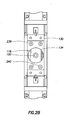
- Figure 2B shows another view of the packer 112 with the upper and lower portions 138a,b removed to show a support plate 239 positioned therebelow.
- the support plate 239 is secured to the base 130 by bolts 240.
- the support plate 239 is configured to act as an internal support for the packer 112 as will be described further herein.
- Figures 3A and 3B show a portion of the probe 112 in greater detail.
- Figure 3A shows the probe 112 in non-engagement with the wall 114 of the wellbore 106.
- Figure 3B shows the probe 112 in engagement with the wall 114 of the wellbore 106.
- the curved outer surface 134 of the packer 118 may be shaped to conform to the wall 114 of the wellbore 106.
- the packer 118 may be a flexible member made of, for example, an elastomeric material (e.g., rubber) compressible against the wall 114 of the wellbore 106 for sealing engagement therewith.
- the packer 118 may be adhered onto the base 130 using an epoxy, adhesive or other bonding agent.
- Support plate 239 may extend from the base 130 for supporting the packer 118.
- the support plate 239 may be, for example, a metal component operatively connected to the base 130 as shown, or integral therewith.
- the support plate 239 may have a raised lip 342 forming a raised support ring along an inner diameter thereof extending a distance into the packer 118 for retaining the packer 118 in a desired position on the base 130 and/or for supporting the packer 118 in sealing engagement against the wall 114 of the wellbore 106.
- the packer 118 may be provided with a ring channel 344 for receiving the support plate 239.
- the packer 118, ring channel 344 and support plate 239 may be configured to provide internal support to the packer 118 as it is moved into engagement with the wall 114 of the wellbore 106 as shown in Figure 3B .
- the support plate 239 may extend into the packer 118 to provide an inner mechanical structure to support the packer 118 as it is pressed against the wall 114.
- the packer 118 may deform as it is pressed against the wall 114.
- the support plate 239 may restrict the amount of deformation, thereby retaining the packer 118 in a sealed position against the wall 114 and providing internal support.
- the angle, length and shape of the ring channel 344 and support plate 239 may be configured to enhance support of the packer 118.
- the raised lip 342 has an S-shaped configuration extending a horizontal distance d 1 (e.g., from about 3mm to about 30 mm) and a vertical distance d 2 (e.g., from about 3mm to about 15 mm) into the packer 118 at a first inward angle ⁇ 1 (e.g., from about 10 degrees to about 60 degrees) and a second inward angle ⁇ 2 (e.g., from about +60 degrees to about -60 degrees).
- the support plate 239 extends into the packer 118 from an outer perimeter 346 and from a base surface 348 of the packer 118. While a specific configuration is depicted, it will be appreciated that the support plate 239 and ring channel 344 may extend at various distances and angles in various shapes through various surfaces of the packer 118.
- the inlet channel 136 of the packer 118 has an outwardly tapered outer portion 350 adjacent the outer surface 134, and an inner portion 352 adjacent the base surface 348, both shaped to receivingly engage the inlet 120.
- the inlet channel 136 may taper outwardly at an angle ⁇ 1 (e.g., from about 5 degrees to about 45 degrees) along the tapered outer portion 350 defining a diameter D 1 (dependent on the diameter D2 which is about the same as the outer diameter of the probe inlet 120), and a height h (e.g from about 5mm to about 20mm) along the outer surface 134.
- At least a portion of the tapered outer portion 350 may taper at a desired angle to provide the desired space to allow insertion of the inlet 120 and/or sealing engagement thereabout.
- the shape of the inlet channel 136 may be configured to facilitate insertion of the inlet 120 into the inlet channel 136 in a manner that prevents damage to the packer 118.
- the tapered outer portions 350 may be configured to provide space to facilitate insertion of the inlet 120 into the packer 118 during non-engagement.
- the shape of the inlet channel 136 may also be configured to facilitate sealing between the packer 118 and the inlet 120 when in the engagement position as shown in Figure 3B .
- the inlet channel 136 of the packer 118 may close about the inlet 120 as the packer 118 is compressed against the wall 114 of the wellbore 106. Once a seal is formed, fluid may flow from the formation into the inlet 120 as indicated by the arrows.
- the packer 118 can experience various stresses when in use.
- the shape of the packer 118 is provided with the ring channel 344 and the tapered inlet channel 136 that can receive increased stress.
- the mechanical structure of the support plate 239 and the inlet 120 may be positioned in the high stress regions of the packer 118 to support the packer 118 where it receives increased stresses. This configuration may be manipulated to address high stresses that can be experienced by the packer 118 when in use, thereby helping to reduce potential damage, wear and/or failure relating to the packer 118.
- FIGS 5A-6B show various views of alternate probes 512a,b usable as the probe 112 of Figure 1 .
- the alternate probes 512a,b have packers 518a,b bonded to the base 130 of a downhole tool, such as the downhole tool 104 of Figure 1 .
- the alternate probes 512a,b are also provided with perimeter (or external) supports, or packer stoppers 556a,b, positioned about a perimeter 546a,b for providing support thereto.
- the alternate probe 512a may have a cylindrical packer 518a with a cylindrical inlet channel 536a positioned on the base 130.
- the packer stopper 556a is a ring shaped member positioned on the base 130 about the perimeter 546a of the packer 518a.
- the packer stopper 556a has a triangular cross-section defining an outer surface 558a at an angle aligned with the perimeter 546a of the packer 518a shaped for alignment with the wall 114 of the wellbore 106.
- the triangular cross-section also defines an inner surface 560a angled away from the perimeter 546a of the packer 518a to provide a gap 562a therebetween.
- the gap 562a provides space to allow the packer 518a to expand as it is compressed against the wall 114 of the wellbore 106 as shown in Figure 5B .
- the inner surface 560a may be at an angle ⁇ (e.g., from about 45 degrees to about 10 degrees) radially rotated a distance on either side of a centerline of the probe 518a and positioned along a radius r extending from an axis z of the wellbore 106.
- the alternate probe 512b may have a packer 518b with a tapered perimeter 546b positioned on the base 130.
- the packer stopper 556b is a ring shaped member positioned on the base 130 about the perimeter 546b of the packer 518b.
- the packer stopper 556b has a trapezoidal cross-section defining an outer surface 558b at a sloped angle to the base 130.
- the trapezoidal cross-section also defines a flat inner surface 560b to provide support to the packer 518b.
- the tapered perimeter 546b defines a gap 562b between the packer 518b and the packer stopper 556b.
- the gap 562b provides space to allow the packer 518b to expand as it is compressed against the wall 114 of the wellbore 106 as shown in Figure 6B .
- the tapered perimeter 546b may be at a sloped angle ⁇ (e.g., from about 45 degrees to about 5 degrees) to the inner surface 560b of the packer stopper 556b.
- Figure 7 is a flow chart depicting a method 700 of forming a seal between a downhole tool and a wall of a wellbore.
- the method involves providing 770 the downhole tool with a probe including a probe inlet, a base positionable about the downhole tool about the probe inlet, a packer positionable on the base, and a raised packer support ring and/or a packer stopper for supporting the packer.
- the method 700 further involves positioning 772 the probe against the wall of the wellbore; and forming 774 a seal between the packer and the wall of the wellbore by supporting the packer with the raised packer support and/or the packer stopper while compressing the packer against the wall of the wellbore.
- the method 700 may also involve other steps, such as establishing fluid communication between the subterranean formation and the probe inlet and drawing fluid from the subterranean formation into the downhole tool. The steps may be performed in any order and repeated as desired.
Landscapes
- Life Sciences & Earth Sciences (AREA)
- Engineering & Computer Science (AREA)
- Geology (AREA)
- Mining & Mineral Resources (AREA)
- Physics & Mathematics (AREA)
- Environmental & Geological Engineering (AREA)
- Fluid Mechanics (AREA)
- General Life Sciences & Earth Sciences (AREA)
- Geochemistry & Mineralogy (AREA)
- Investigation Of Foundation Soil And Reinforcement Of Foundation Soil By Compacting Or Drainage (AREA)
Priority Applications (3)
| Application Number | Priority Date | Filing Date | Title |
|---|---|---|---|
| EP11290552.6A EP2599954A3 (fr) | 2011-11-30 | 2011-11-30 | Packer de sonde et son procédé d'utilisation |
| PCT/US2012/063767 WO2013081782A1 (fr) | 2011-11-30 | 2012-11-07 | Garniture de sonde et son procédé d'utilisation |
| US14/361,969 US20140318817A1 (en) | 2011-11-30 | 2012-11-07 | Probe Packer and Method of Using Same |
Applications Claiming Priority (1)
| Application Number | Priority Date | Filing Date | Title |
|---|---|---|---|
| EP11290552.6A EP2599954A3 (fr) | 2011-11-30 | 2011-11-30 | Packer de sonde et son procédé d'utilisation |
Publications (2)
| Publication Number | Publication Date |
|---|---|
| EP2599954A2 true EP2599954A2 (fr) | 2013-06-05 |
| EP2599954A3 EP2599954A3 (fr) | 2014-04-09 |
Family
ID=47192189
Family Applications (1)
| Application Number | Title | Priority Date | Filing Date |
|---|---|---|---|
| EP11290552.6A Withdrawn EP2599954A3 (fr) | 2011-11-30 | 2011-11-30 | Packer de sonde et son procédé d'utilisation |
Country Status (3)
| Country | Link |
|---|---|
| US (1) | US20140318817A1 (fr) |
| EP (1) | EP2599954A3 (fr) |
| WO (1) | WO2013081782A1 (fr) |
Families Citing this family (1)
| Publication number | Priority date | Publication date | Assignee | Title |
|---|---|---|---|---|
| US9777572B2 (en) | 2014-11-17 | 2017-10-03 | Baker Hughes Incorporated | Multi-probe reservoir sampling device |
Citations (5)
| Publication number | Priority date | Publication date | Assignee | Title |
|---|---|---|---|---|
| US7114385B2 (en) | 2004-10-07 | 2006-10-03 | Schlumberger Technology Corporation | Apparatus and method for drawing fluid into a downhole tool |
| US7121338B2 (en) | 2004-01-27 | 2006-10-17 | Halliburton Energy Services, Inc | Probe isolation seal pad |
| US20070151727A1 (en) | 2005-12-16 | 2007-07-05 | Schlumberger Technology Corporation | Downhole Fluid Communication Apparatus and Method |
| US7458419B2 (en) | 2004-10-07 | 2008-12-02 | Schlumberger Technology Corporation | Apparatus and method for formation evaluation |
| US7585786B2 (en) | 2003-12-10 | 2009-09-08 | Samsung Electronics Co., Ltd. | Methods of forming spin-on-glass insulating layers in semiconductor devices and associated semiconductor device |
Family Cites Families (5)
| Publication number | Priority date | Publication date | Assignee | Title |
|---|---|---|---|---|
| US3295615A (en) * | 1965-10-22 | 1967-01-03 | Schlumberger Well Surv Corp | Formation-testing apparatus |
| US7128144B2 (en) * | 2003-03-07 | 2006-10-31 | Halliburton Energy Services, Inc. | Formation testing and sampling apparatus and methods |
| US7216533B2 (en) * | 2004-05-21 | 2007-05-15 | Halliburton Energy Services, Inc. | Methods for using a formation tester |
| US7584655B2 (en) * | 2007-05-31 | 2009-09-08 | Halliburton Energy Services, Inc. | Formation tester tool seal pad |
| EP2432969B1 (fr) * | 2009-05-20 | 2018-06-20 | Halliburton Energy Services, Inc. | Patin de testeur de formation |
-
2011
- 2011-11-30 EP EP11290552.6A patent/EP2599954A3/fr not_active Withdrawn
-
2012
- 2012-11-07 WO PCT/US2012/063767 patent/WO2013081782A1/fr not_active Ceased
- 2012-11-07 US US14/361,969 patent/US20140318817A1/en not_active Abandoned
Patent Citations (7)
| Publication number | Priority date | Publication date | Assignee | Title |
|---|---|---|---|---|
| US7585786B2 (en) | 2003-12-10 | 2009-09-08 | Samsung Electronics Co., Ltd. | Methods of forming spin-on-glass insulating layers in semiconductor devices and associated semiconductor device |
| US7121338B2 (en) | 2004-01-27 | 2006-10-17 | Halliburton Energy Services, Inc | Probe isolation seal pad |
| US7114385B2 (en) | 2004-10-07 | 2006-10-03 | Schlumberger Technology Corporation | Apparatus and method for drawing fluid into a downhole tool |
| US7458419B2 (en) | 2004-10-07 | 2008-12-02 | Schlumberger Technology Corporation | Apparatus and method for formation evaluation |
| US7793713B2 (en) | 2004-10-07 | 2010-09-14 | Schlumberger Technology Corporation | Apparatus and method for formation evaluation |
| US20070151727A1 (en) | 2005-12-16 | 2007-07-05 | Schlumberger Technology Corporation | Downhole Fluid Communication Apparatus and Method |
| US20100155053A1 (en) | 2005-12-16 | 2010-06-24 | Chen Tao | Downhole fluid communication apparatus and method |
Also Published As
| Publication number | Publication date |
|---|---|
| EP2599954A3 (fr) | 2014-04-09 |
| US20140318817A1 (en) | 2014-10-30 |
| WO2013081782A1 (fr) | 2013-06-06 |
Similar Documents
| Publication | Publication Date | Title |
|---|---|---|
| US10344583B2 (en) | Acoustic housing for tubulars | |
| CN110168191B (zh) | 对钻井进行封堵和压力测试的方法 | |
| US9580981B2 (en) | Liner hanger system | |
| US10697288B2 (en) | Dual transducer communications node including piezo pre-tensioning for acoustic wireless networks and method employing same | |
| CN104011326B (zh) | 使用处理井的导向孔作为监测井实时监测和发送水力压裂地震事件至表面的系统 | |
| AU2016269518B2 (en) | Improved liner hanger system | |
| CN107013181B (zh) | 可溶解桥塞及桥塞压裂系统 | |
| CA2810332A1 (fr) | Systemes et procedes pour surveiller un parametre d'une formation souterraine a l'aide de materiaux pouvant gonfler | |
| CN108699898B (zh) | 用于高压高温(hpht)应用的密封设备 | |
| GB2444060A (en) | Swellable downhole apparatus | |
| MX2013005077A (es) | Arpones para tuberia de revestimiento y sistemas y metodos relacionados. | |
| WO2014184586A2 (fr) | Surveillance et transmission de données de puits de forage jusqu'à la surface | |
| US10196870B2 (en) | External slip having expandable slots and a retainer | |
| US10948619B2 (en) | Acoustic transducer | |
| EP2599954A2 (fr) | Packer de sonde et son procédé d'utilisation | |
| CA2341060C (fr) | Methode et dispositif d'ancrage d'outils dans un trou fore chemise | |
| CN102224319A (zh) | 用于将元件固定在钻孔中的方法和系统 | |
| US20070062693A1 (en) | System, method, and apparatus for degassing tool for coal bed methane gas wells | |
| US10718209B2 (en) | Single packer inlet configurations | |
| CN102812202B (zh) | 将分配器导管壳与井口连接的高压密封适配器和完井方法 | |
| US20190226337A1 (en) | Enhanced Downhole Packer | |
| US10941631B2 (en) | Cementing plug system | |
| US9115571B2 (en) | Packer including support member with rigid segments |
Legal Events
| Date | Code | Title | Description |
|---|---|---|---|
| PUAI | Public reference made under article 153(3) epc to a published international application that has entered the european phase |
Free format text: ORIGINAL CODE: 0009012 |
|
| AK | Designated contracting states |
Kind code of ref document: A2 Designated state(s): AL AT BE BG CH CY CZ DE DK EE ES FI FR GB GR HR HU IE IS IT LI LT LU LV MC MK MT NL NO PL PT RO RS SE SI SK SM TR |
|
| AX | Request for extension of the european patent |
Extension state: BA ME |
|
| PUAL | Search report despatched |
Free format text: ORIGINAL CODE: 0009013 |
|
| AK | Designated contracting states |
Kind code of ref document: A3 Designated state(s): AL AT BE BG CH CY CZ DE DK EE ES FI FR GB GR HR HU IE IS IT LI LT LU LV MC MK MT NL NO PL PT RO RS SE SI SK SM TR |
|
| AX | Request for extension of the european patent |
Extension state: BA ME |
|
| RIC1 | Information provided on ipc code assigned before grant |
Ipc: E21B 49/10 20060101ALI20140303BHEP Ipc: E21B 33/12 20060101AFI20140303BHEP |
|
| 17P | Request for examination filed |
Effective date: 20141009 |
|
| RAX | Requested extension states of the european patent have changed |
Extension state: BA Payment date: 20141009 Extension state: ME Payment date: 20141009 |
|
| RBV | Designated contracting states (corrected) |
Designated state(s): AL AT BE BG CH CY CZ DE DK EE ES FI FR GB GR HR HU IE IS IT LI LT LU LV MC MK MT NL NO PL PT RO RS SE SI SK SM TR |
|
| 17Q | First examination report despatched |
Effective date: 20160623 |
|
| STAA | Information on the status of an ep patent application or granted ep patent |
Free format text: STATUS: THE APPLICATION IS DEEMED TO BE WITHDRAWN |
|
| 18D | Application deemed to be withdrawn |
Effective date: 20190118 |