EP2600008B1 - Turbomaschinengehäuseanordnung mit Hohlraum zum Schaufelberstschutz - Google Patents
Turbomaschinengehäuseanordnung mit Hohlraum zum Schaufelberstschutz Download PDFInfo
- Publication number
- EP2600008B1 EP2600008B1 EP12189778.9A EP12189778A EP2600008B1 EP 2600008 B1 EP2600008 B1 EP 2600008B1 EP 12189778 A EP12189778 A EP 12189778A EP 2600008 B1 EP2600008 B1 EP 2600008B1
- Authority
- EP
- European Patent Office
- Prior art keywords
- casing
- casing element
- elements
- turbomachine
- assembly
- Prior art date
- Legal status (The legal status is an assumption and is not a legal conclusion. Google has not performed a legal analysis and makes no representation as to the accuracy of the status listed.)
- Not-in-force
Links
- 239000011800 void material Substances 0.000 claims description 9
- 239000011248 coating agent Substances 0.000 claims description 3
- 238000000576 coating method Methods 0.000 claims description 3
- 239000010410 layer Substances 0.000 description 13
- 239000000463 material Substances 0.000 description 7
- 230000014759 maintenance of location Effects 0.000 description 6
- 230000007246 mechanism Effects 0.000 description 5
- 239000004411 aluminium Substances 0.000 description 3
- 229910052782 aluminium Inorganic materials 0.000 description 3
- XAGFODPZIPBFFR-UHFFFAOYSA-N aluminium Chemical compound [Al] XAGFODPZIPBFFR-UHFFFAOYSA-N 0.000 description 3
- 230000000712 assembly Effects 0.000 description 2
- 238000000429 assembly Methods 0.000 description 2
- 230000008901 benefit Effects 0.000 description 2
- 238000011068 loading method Methods 0.000 description 2
- 239000002184 metal Substances 0.000 description 2
- 229910052751 metal Inorganic materials 0.000 description 2
- 239000007787 solid Substances 0.000 description 2
- OKTJSMMVPCPJKN-UHFFFAOYSA-N Carbon Chemical compound [C] OKTJSMMVPCPJKN-UHFFFAOYSA-N 0.000 description 1
- 229920000784 Nomex Polymers 0.000 description 1
- 229910000831 Steel Inorganic materials 0.000 description 1
- RTAQQCXQSZGOHL-UHFFFAOYSA-N Titanium Chemical compound [Ti] RTAQQCXQSZGOHL-UHFFFAOYSA-N 0.000 description 1
- 239000004760 aramid Substances 0.000 description 1
- 229920003235 aromatic polyamide Polymers 0.000 description 1
- 230000004323 axial length Effects 0.000 description 1
- 238000005452 bending Methods 0.000 description 1
- 229910052799 carbon Inorganic materials 0.000 description 1
- 239000002131 composite material Substances 0.000 description 1
- 230000003247 decreasing effect Effects 0.000 description 1
- 239000003822 epoxy resin Substances 0.000 description 1
- 239000000835 fiber Substances 0.000 description 1
- 239000011152 fibreglass Substances 0.000 description 1
- 239000006260 foam Substances 0.000 description 1
- 239000006261 foam material Substances 0.000 description 1
- 239000012634 fragment Substances 0.000 description 1
- 239000003365 glass fiber Substances 0.000 description 1
- 230000003116 impacting effect Effects 0.000 description 1
- 239000011229 interlayer Substances 0.000 description 1
- 238000004519 manufacturing process Methods 0.000 description 1
- 239000007769 metal material Substances 0.000 description 1
- 238000010137 moulding (plastic) Methods 0.000 description 1
- 239000004763 nomex Substances 0.000 description 1
- 230000000149 penetrating effect Effects 0.000 description 1
- 229920000647 polyepoxide Polymers 0.000 description 1
- 230000009467 reduction Effects 0.000 description 1
- 239000011208 reinforced composite material Substances 0.000 description 1
- 230000002787 reinforcement Effects 0.000 description 1
- 230000004044 response Effects 0.000 description 1
- 239000010959 steel Substances 0.000 description 1
- 239000010936 titanium Substances 0.000 description 1
- 229910052719 titanium Inorganic materials 0.000 description 1
- 230000007704 transition Effects 0.000 description 1
Images


Classifications
-
- F—MECHANICAL ENGINEERING; LIGHTING; HEATING; WEAPONS; BLASTING
- F01—MACHINES OR ENGINES IN GENERAL; ENGINE PLANTS IN GENERAL; STEAM ENGINES
- F01D—NON-POSITIVE DISPLACEMENT MACHINES OR ENGINES, e.g. STEAM TURBINES
- F01D21/00—Shutting-down of machines or engines, e.g. in emergency; Regulating, controlling, or safety means not otherwise provided for
- F01D21/04—Shutting-down of machines or engines, e.g. in emergency; Regulating, controlling, or safety means not otherwise provided for responsive to undesired position of rotor relative to stator or to breaking-off of a part of the rotor, e.g. indicating such position
- F01D21/045—Shutting-down of machines or engines, e.g. in emergency; Regulating, controlling, or safety means not otherwise provided for responsive to undesired position of rotor relative to stator or to breaking-off of a part of the rotor, e.g. indicating such position special arrangements in stators or in rotors dealing with breaking-off of part of rotor
-
- F—MECHANICAL ENGINEERING; LIGHTING; HEATING; WEAPONS; BLASTING
- F04—POSITIVE - DISPLACEMENT MACHINES FOR LIQUIDS; PUMPS FOR LIQUIDS OR ELASTIC FLUIDS
- F04D—NON-POSITIVE-DISPLACEMENT PUMPS
- F04D27/00—Control, e.g. regulation, of pumps, pumping installations or pumping systems specially adapted for elastic fluids
- F04D27/02—Surge control
- F04D27/0292—Stop safety or alarm devices, e.g. stop-and-go control; Disposition of check-valves
-
- F—MECHANICAL ENGINEERING; LIGHTING; HEATING; WEAPONS; BLASTING
- F04—POSITIVE - DISPLACEMENT MACHINES FOR LIQUIDS; PUMPS FOR LIQUIDS OR ELASTIC FLUIDS
- F04D—NON-POSITIVE-DISPLACEMENT PUMPS
- F04D29/00—Details, component parts, or accessories
- F04D29/40—Casings; Connections of working fluid
- F04D29/52—Casings; Connections of working fluid for axial pumps
- F04D29/522—Casings; Connections of working fluid for axial pumps especially adapted for elastic fluid pumps
- F04D29/526—Details of the casing section radially opposing blade tips
-
- Y—GENERAL TAGGING OF NEW TECHNOLOGICAL DEVELOPMENTS; GENERAL TAGGING OF CROSS-SECTIONAL TECHNOLOGIES SPANNING OVER SEVERAL SECTIONS OF THE IPC; TECHNICAL SUBJECTS COVERED BY FORMER USPC CROSS-REFERENCE ART COLLECTIONS [XRACs] AND DIGESTS
- Y02—TECHNOLOGIES OR APPLICATIONS FOR MITIGATION OR ADAPTATION AGAINST CLIMATE CHANGE
- Y02T—CLIMATE CHANGE MITIGATION TECHNOLOGIES RELATED TO TRANSPORTATION
- Y02T50/00—Aeronautics or air transport
- Y02T50/60—Efficient propulsion technologies, e.g. for aircraft
Definitions
- This invention relates to a turbomachine casing assembly and particularly, but not exclusively, to a casing assembly for the fan of a turbofan gas turbine engine.
- Turbofan gas turbine engines for powering aircraft generally comprise inter alia a core engine, which drives a fan.
- the fan comprises a number of radially extending fan blades mounted on a fan rotor which is enclosed by a generally cylindrical fan casing.
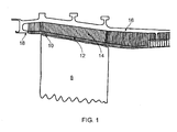
- FIG. 1 shows a partial cross-section of such a fan track liner.
- the detached fan blade 8 travels radially outward, penetrating the attrition liner 10, septum 12 and aluminium honeycomb layer 14 until it reaches the metallic fan casing 16. The fan blade 8 then travels forwards where it is trapped by the hook 18.
- the fan track liner must therefore be relatively weak in order that any released blade or fragment thereof can penetrate sufficiently to be restrained axially whilst the liner distributes the load applied to the casing barrel as the radial restraint.
- EP 2 495 401 discloses a turbomachine casing assembly having a first casing element locatable radially outward of one or more rotating aerofoil elements of a turbomachine, and a second casing element located radially distal to the first casing element.
- a void is provided between a radially proximal face of the first casing element and a radially proximal face of the second casing element, at the first end of the first casing element.
- the first end of the first casing element is located against a corresponding first end of the second casing element by an energy absorbing element, with the first casing element; comprising a cantilever.
- the cantilever is arranged in a region extending along the first casing element from the first end; and having a pivot axis at a mid-portion thereof. Release of one of the rotating aerofoil elements results in the element, or part thereof, impacting the first casing element which results in the cantilever bending into the void provided between the first and second casing elements. This enables the rotating aerofoil element to be trapped within the casing assembly.
- the fan track liner includes an annular layer of abradable material which surrounds the fan blades. During operation of the engine, the fan blades cut a path into this abradable layer creating a seal against the fan casing and minimising leakage around the blade tips.
- the fan track liner must also be resistant to ice impact loads.
- a rearward portion of the fan track liner is conventionally provided with an annular ice impact panel. This may typically be a glass-reinforced plastic moulding which may also be wrapped with GRP to increase its impact strength. Ice that forms on the fan blades is acted on by both centrifugal and airflow forces, which respectively cause it to move outwards and rearwards before being shed from the blades.
- the geometry of a conventional fan blade is such that the ice is shed from the trailing edge of the blade, strikes the ice impact panel and is deflected without damaging the panel.
- Swept fan blades are increasingly used in turbofan engines as they offer significant advantages in efficiency over conventional fan blades.
- Swept fan blades have a greater chord length at their central portion than conventional fan blades. This greater chordal length means that ice that forms on a swept fan blade follows the same rearward and outward path as on a conventional fan blade but may reach the radially outer tip of the blade before it reaches the trailing edge. It will therefore be shed from the blade tip and may strike the fan track liner forward of the ice impact panel.
- a conventional fan track liner is generally not strong enough along its forward region to withstand ice impact and is therefore generally not suitable for use with swept fan blades. It is not possible simply to strengthen the fan track liner to accommodate ice impact, because this may disrupt the blade trajectory during an FBO event, and thereby compromise the operation of the fan casing containment system.
- a turbomachine casing assembly for enclosing one or more rotating aerofoil elements (150) of a turbomachine, the one or more rotating aerofoil elements (150) having an axis of rotation, the turbomachine casing assembly (100;200) comprising:
- the casing assembly of the present invention allows a shed fan blade to penetrate the first casing element at a first, or forward, end, whilst remaining impervious to ice impact the opposite, or rear, end.
- the competing requirements of fan blade ice shedding loads and fan blade off loads may thus be accommodated in a way that was not previously possible.
- the manner in which this is achieved allows for the potential to tune the casing assembly to optimally fulfil each requirement whilst simultaneously saving weight and easing manufacture.
- the weight of the assembly can be reduced. This increases the weight efficiency of the engine and makes it more attractive for aircraft applications.
- the first interface portion is formed as a first angled face which is inclined at a wedge angle to an axis of rotation of the one or more rotating aerofoil elements.
- the first interface portion as an angled face, inclined at an angle to the axis of rotation of the fan, it is possible to translate radially outward movement of the fan track liner into axial movement of the fan track liner in a direction parallel to the axis of rotation.
- the impact of a detached fan blade striking the fan track liner causes a radially outward motion of the fan track liner which in turn is translated by the first interface portion into an axially rearward motion of the fan track liner.
- the second interface portion is formed as a second angled face which is inclined at the wedge angle.
- the wedge angle is preferably between 30° and 45°.
- This larger axial movement may then be more easily controlled by, for example, the use of conventional resilient elements, such as coil springs.
- first and second casing elements extend circumferentially around the rotating aerofoil elements.
- the first interface portion is formed as a curved face extending distally from the first end of the second casing element towards a second end of the second casing element.
- the first interface portion as a curved face, it becomes possible to provide a non-linear relationship between the radially outward and axially rearward movement of the fan track liner. In this way, it is possible to tailor the response of the fan track liner to predicted impact loadings.
- the second interface portion is formed as a convex protrusion at the first end of the distal face of the first casing element.
- the second interface portion at the forward end of the first casing element is formed as a convex protrusion, it is possible to reduce the contact area between the first and second interface portions. This, in turn, allows for a reduction in the friction between these two portions which can make the casing assembly more responsive to impact loadings.
- the turbomachine casing assembly further comprises one or more resilient elements positioned between a second end of the first casing element and a second end of the second casing element.
- the resilient elements can be arranged to absorb some or all of the loads resulting from the impact of a detached fan blade on the fan track liner.
- the resilient elements take the form of a plurality of coil springs arranged with their axis parallel to the axis of rotation of the aerofoil elements.
- the resilient elements may take the form of conical springs (Belleville washers), leaf springs or shaped rubber elements.
- the resilient elements may be pre-compressed prior to fitting the first casing element to the casing assembly. This simplifies fitting of the first casing element by sliding the first casing element rearwards, locating and securing the first casing element against the second casing assembly and then releasing the resilient elements.
- the turbomachine casing assembly further comprises one or more deformable elements positioned between the second end of the first casing element and the second end of the second casing element.
- the deformable element at the second, or rearward, end of the fan track liner can absorb the energy resulting from the impact of a detached fan blade on the fan track liner.
- the deformable element absorbs the impact energy by plastically deforming, it will remain in its deformed state following the dissipation of the energy associated with the impact event. In this way the hook at the forward end of the second casing element remains exposed following the impact event.
- the one or more deformable elements take the form of crushable tubes.
- the deformable elements may be honeycomb or foam materials.
- the radially proximal face of the first casing element is contiguous with a radially proximal face of the second casing element to form an uninterrupted surface.
- At least one of the first and second interface portions comprises a surface coating such that a coefficient of friction of the at least one coated first and second interface portions is less than that of the respective at least one uncoated first and second interface portions.
- the matching first and second interface portions By coating one or both of the matching first and second interface portions with a friction reducing material layer, it may be possible to reduce the coefficient of friction between the portions as they move relative to one another.
- the turbomachine casing assembly further comprises a plurality of first casing elements, each of the first casing elements being arranged as a circumferential array, each of the first casing elements having a first side and an opposite second side extending from the first end to the second end, the first side of each first casing element overlapping the second side of the respective adjoining first casing element.
- Any detached fan blade will have a circumferential velocity in addition to a radial velocity. Consequently, it is likely that the detached blade will impact several fan track liner elements before becoming trapped by the hook.
- a detached fan blade is able to contiguously deflect a sequence of adjoining fan track liner elements without encountering a step between a deflected element and an undeflected element which might project the blade out of the engine.
- the wedge angle varies across at least one of the first casing elements from the first side to the second side.
- a larger wedge angle will reduce the compliance of the first end of the first casing element to the impact of a detached blade.
- the compliance of the first casing element may be configured to increase across its width. This reduces the impact load required to initially deform a first edge of a first casing element which, in turn, makes it easier for a detached blade to transition between adjacent first casing elements.
- the first casing element comprising a rack disposed at the second end thereof
- the second casing element comprising a corresponding pawl disposed at the second end thereof, and wherein in use the pawl engages with the rack to allow uni-directional movement of the first casing element along the axis of rotation.
- each of the deflected liner elements remains in its deflected position. This will leave the hook portion exposed which may improve the blade retention capability of the hook.
- a jet engine fan casing comprising the turbomachine casing assembly according to the first aspect of the invention.
- a gas turbine comprising a turbomachine casing assembly according to the first aspect of the invention.
- a fan casing assembly according to a first embodiment of the invention is designated generally by the reference numeral 100 and comprises a first casing element 110 and a second casing element 130.
- the first casing element 110 has a first end 112, a second end 114, a radially proximal face 116 and a radially distal face 118
- the second casing element 130 has a first end 132, a second end 134, a radially proximal face 136 and a radially distal face 138.
- the first casing element 110 at least partially encloses one or more rotating aerofoil structures 150.
- These aerofoil structures 150 may comprise blades of a turbomachine, in particular compressor fan blades.
- the second casing element 130 is disposed radially distal to the first casing element 110.
- the turbomachine casing assembly 100 comprises a plurality of first casing elements 110 circumferentially disposed about a curve defined by the blade tip path of the one or more aerofoil structures 150 of the turbomachine.
- the first casing element 110 is typically formed as a filled Nomex honeycomb material, while the second casing element 130 may be metallic and may, for example, be formed of aluminium, titanium, steel or any other suitable metal.
- Each first casing element 110 comprises a radially proximal face 116 in the form of an abradable layer 120.
- An infill member 156 is positioned between the first and second casing elements 110,130 and is attached to the abradable layer 120.
- An exemplary material for the abradable layer 120 is an epoxy resin, which may be curable at room temperature.
- the abradable layer 120 provides a surface against which the fan blade 150 is able to rub and cut a path for itself. For example, the fan blades 150 may rub against the abradable layer 120 and form a seal during normal engine operation.
- the infill member 156 may be formed from a frangible or crushable structure, such as a foam or honeycomb material which provides structural reinforcement.
- the honeycomb material may be formed from a metal, such as aluminium, or from a non-metallic material, such as NomexTM (a flame resistant aramid material).
- the infill member 156 may be formed separately from the first casing element 110, and positioned between the first and second casing elements 110,130.
- a septum layer (not shown) may be provided as an interlayer between the abradable layer 120 and the infill member 156.
- the septum layer may be metallic or may be formed from a carbon fibre or glass fibre reinforced composite material.
- the forward portion of the radially distal face 118 of the first casing element 110 is angled relative to the corresponding radially proximal face 136 of the second casing element 130 such that a void 160 is defined between the first and second casing elements 110,130 at their forward, or first, ends 112,132.
- the second casing element 130 comprises a fan blade retaining feature 140 disposed at a forward, or first, end 132 thereof, in the form of a hooked portion 140.
- the hooked portion 140 extends radially inwardly and then axially in a rearward direction.
- a first interface portion 170 in the form of a first angled face 172 is located at the first end 132 of the second casing element 130.
- the first angled face 172 is oriented at a wedge angle W to the axis of rotation 152 of the rotating aerofoil structures 150.
- the wedge angle W is 30°, i.e. the first angled face is angled at 30° to the axis of rotation.
- a second interface portion 176 in the form of a second angled face 178 is located at the first end 112 of the first casing element 110.
- the second angled face 176 is also oriented at a wedge angle W to the axis of rotation 152, and is in sliding contact with the first angled face 172.
- a resilient element 184 is positioned at the second end 114 of the first casing element 110.
- the resilient element 184 takes the form of a plurality of coil springs 184 arranged with their axes parallel to the axis of rotation 152.
- Each coil spring 184 extends between the second end 114 of the first casing element 110 and the second end 134 of the second casing element 130.
- a spring platform 186 is positioned between the spring 184 and the second end 114 of the first casing element 110.
- Each spring 184 is located between the second ends 114,134 of the first and second casing elements 110,130 by a respective guide post 188.
- a ratchet retention mechanism 190 is provided at the juncture of the second ends 114,134 of the first and second casing elements 110,130, as shown in Figure 6 .
- This mechanism 190 takes the form of a linear rack 192 which is disposed at the second end 114 of the first casing element 110 and a pawl 194 disposed on the second end 134 of the second casing element 130.
- the pawl 194 engages with the rack 192 such that the first casing element 110 is able to move axially rearwards (i.e. in a direction from the first end to the second end) but is not able to return to its original position.
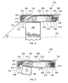
- a fan blade 150 In use, when a fan blade 150 becomes detached, it travels in a generally radially outward direction as indicated by the arrow A in Figure 3 .
- the detached blade first strikes the radially proximal face 116 of the first end 112 of the first casing element 110. This impact causes the first end 112 to deflect radially outwards, exposing the hook 140.
- the second angled face 178 slides along the first angled face 172 which results in the first casing assembly 110 moving axially rearwards, as indicated by the arrow B in Figure 3 .
- first and second angled faces 172,178 are positioned flush to one another.
- the first end 112 of the first casing element 110 deforms radially outwards. This results in the area of contact between the first and second angled faces 172,178 changing from an area of contact to a line of contact, thus reducing the frictional force between the two faces 172,178. This ensures that, once the first casing element 110 has been initially deflected sufficiently by a detached fan blade 150, the deformation continues in order to arrest the fan blade 150 in the casing assembly 100.
- the energy associated with the impact event is then transferred to and absorbed by the springs 184.
- the ratchet retention mechanism operates (i.e. the pawl 194 engages with the rack 192) to prevent the first casing element 110 from returning to its original position once the impact energy has been absorbed by the springs 184.
- the blade tip engages with the hook 140 and subsequently becomes arrested by the casing assembly 100. In other words, the kinetic energy is removed from the detached blade 150.
- a fan casing assembly according to a second embodiment of the invention is designated generally by the reference numeral 200.
- Features of the fan casing assembly 200 which correspond to those of fan casing assembly 100 have been given corresponding reference numerals for ease of reference.
- the fan casing assembly 200 has a first casing element 210 and a second casing element 130.
- the first casing element 210 has a first end 212, a second end 214, a radially proximal face 216 and a radially distal face 218.
- the radially proximal face 216 comprises an abradable layer 120.
- the radially distal face 218 of the first casing element 210 corresponds to the radially proximal face 136 of the second casing element 130.
- the radially proximal and distal faces 216,218 of the first casing element 210 are spaced apart from one another with an infill member 256 positioned therebetween.
- a second interface portion 276 in the form of a convex protrusion 278 is located at the first end 212 of the first casing element 210.
- the convex protrusion 278 is arranged in sliding contact with the first angled face 172.
- a detached fan blade 150 travels in a generally radially outward direction as indicated by the arrow A in Figure 5 .
- the detached blade first strikes the radially proximal face 216 of the first end 212 of the first casing element 210. This impact causes the first end 212 to deflect radially outwards, exposing the hook 140.
- the convex protrusion 278 slides along the first angled face 172 which results in the first casing assembly 210 moving axially rearwards, as indicated by the arrow B in Figure 5 .
- the energy associated with the impact event is then transferred to and absorbed by the springs 184.
- the ratchet retention mechanism operates (i.e. the pawl 194 engages with the rack 192) to prevent the first casing element 210 from returning to its original position once the impact energy has been absorbed by the springs 184.
- the blade tip engages with the hook 140 and subsequently becomes arrested by the casing assembly 200.
- a fan casing assembly according to a third embodiment of the invention is designated generally by the reference numeral 300.
- Features of the fan casing assembly 300 which correspond to those of fan casing assembly 100 have been given corresponding reference numerals for ease of reference.
- the fan casing assembly 300 has a plurality of first casing elements 310 each comprising a first end 312, a second end 314 and a radially proximal face 316.
- the first casing elements 310 further comprise a first edge 318 and an opposite second edge 320; the first and second edges 318,320 each extending from the first end 312 to the second end 314.
- Each of the first and second edges 318,320 comprises a respective first and second edge step 322,324 located at a mid-portion thereof.
- Each first edge step 322 on the first edge 318 of a first casing element 310 co-operates with the second edge step 324 on the second edge 320 of the adjoining first casing element 310.
- Figure 7 shows a partial, schematic view on the radially proximal faces 316 of the first casing elements 310 viewed in a radially outward direction with the direction of motion of the fan blades indicated by the arrow C.
- first and second interface portions 170,176;276 causes the first casing element 310 to move in the direction indicated by arrow D. This motion is then transferred by the co-operating second and first edge steps 324,322 to the adjoining first casing element 310 as indicated by the arrow E. In this way, there is a contiguous radial outward deformation of the first casing elements 310 and the detached fan blade does not encounter a step between adjoining first casing elements which might hinder its arrest in the casing assembly 100.
- the casing assemblies disclosed herein are equally applicable to solid and hollow fan blades and may be used with light-weight (hollow line-core or solid composite) fan blades.
- the casing assemblies may also be used with aerofoil structures, e.g. fan blades, comprising a foreign object damage resistant member at the front of the aerofoil structure, such as a picture frame or metallic sheath.
- aerofoil structures e.g. fan blades, comprising a foreign object damage resistant member at the front of the aerofoil structure, such as a picture frame or metallic sheath.
- the present disclosure may also be applied to swept or unswept aerofoil structures.
Landscapes
- Engineering & Computer Science (AREA)
- Mechanical Engineering (AREA)
- General Engineering & Computer Science (AREA)
- Structures Of Non-Positive Displacement Pumps (AREA)
Claims (14)
- Turbomaschinengehäuseanordnung (100; 200) zum Umschließen eines oder mehrerer sich drehender Tragflächenelemente (150) einer Turbomaschine, wobei das eine oder die mehreren sich drehenden Tragflächenelemente (150) eine Rotationsachse aufweisen, wobei die Turbomaschinengehäuseanordnung (100; 200) folgendes umfasst:ein erstes Gehäuseelement (110; 210), das radial auswärts zu dem einen oder den mehreren sich drehenden Tragflächenelementen (150) angeordnet ist und ein erstes Ende (112; 212) aufweist;ein zweites Gehäuseelement (130), das radial distal zu dem ersten Gehäuseelement (110; 210) angeordnet ist und ein erstes Ende (132) aufweist; undeinen freien Raum (160), der zwischen dem ersten Gehäuseelement (110; 210) und dem zweiten Gehäuseelement (130) an dem ersten Ende (112; 212) des ersten Gehäuseelements (110; 210) vorgesehen ist;wobei jedes der ersten und zweiten Gehäuseelemente (110; 210, 130) an deren ersten Ende (112; 212, 132) entsprechende zusammenwirkende erste und zweite Grenzflächenabschnitte (170, 176; 276) umfasst;
wobei bei einem Ausfall eines der sich drehenden Tragflächenelemente (150) der zweite Grenzflächenabschnitt (176; 276) entlang dem ersten Grenzflächenabschnitt (170) rutscht, und wobei das erste Ende (112; 212) des ersten Gehäuseelements (110; 210) in den freien Raum (160) eintritt;
dadurch gekennzeichnet, dass das erste Gehäuseelement (110; 210) ferner eine Stange (192) umfasst, die an dessen zweiten Ende (114; 214) angeordnet ist, wobei das zweite Gehäuseelement (130) ferner eine entsprechende Klinke (194) umfasst, die an dessen zweiten Ende (134) angeordnet ist, und wobei die Klinke (194) im Einsatz mit der Stange (192) eingreift, um eine unidirektionale Bewegung des ersten Gehäuseelements (110; 210) entlang der Rotationsachse zu ermöglichen. - Turbomaschinengehäuseanordnung (100; 200) nach Anspruch 1, wobei der erste Grenzflächenabschnitt (170) als eine erste schräge Fläche (172) ausgebildet ist, die in einem Keilwinkel (W) zu der Rotationsachse geneigt ist.
- Turbomaschinengehäuseanordnung (100; 200) nach Anspruch 2, wobei der zweite Grenzflächenabschnitt (176) als eine zweite schräge Fläche (178) ausgebildet ist, die in einem Keilwinkel (W) geneigt ist.
- Turbomaschinengehäuseanordnung (100; 200) nach Anspruch 2 oder 3, wobei der Keilwinkel (W) vorzugsweise zwischen 30° und 45° liegt.
- Turbomaschinengehäuseanordnung (100; 200) nach einem der Ansprüche 1 bis 4, wobei sich die ersten und zweiten Gehäuseelemente (110; 210, 130) umfänglich um die sich drehenden Tragflächenelemente (150) erstrecken.
- Turbomaschinengehäuseanordnung (100; 200) nach Anspruch 1, wobei der erste Grenzflächenabschnitt (170) als eine gekrümmte Fläche ausgebildet ist, die sich von dem ersten Ende (132) des zweiten Gehäuseelements (130) in Richtung eines zweiten Endes (134) des zweiten Gehäuseelements (130) erstreckt.
- Turbomaschinengehäuseanordnung (100; 200) nach Anspruch 2 oder 6, wobei der zweite Grenzflächenabschnitt (276) als ein konvexer Vorsprung (278) an dem ersten Ende der distalen Fläche (118; 218) des ersten Gehäuseelements (110; 210) ausgebildet ist.
- Turbomaschinengehäuseanordnung (100; 200) nach einem der Ansprüche 1 bis 7, ferner umfassend ein oder mehrere elastische Elemente (184), die zwischen einem zweiten Ende (114; 214) des ersten Gehäuseelements (110; 210) und einem zweiten Ende (134) des zweiten Gehäuseelements (130) positioniert sind.
- Turbomaschinengehäuseanordnung (100; 200) nach einem der Ansprüche 1 bis 8, ferner umfassend ein oder mehrere verformbare Elemente, die zwischen dem zweiten Ende (114; 214) des ersten Gehäuseelements (110; 210) und dem zweiten Ende (134) des zweiten Gehäuseelements (130) positioniert sind.
- Turbomaschinengehäuseanordnung (100; 200) nach einem der Ansprüche 1 bis 9, wobei die radial proximale Fläche (116; 216) des ersten Gehäuseelements (110; 210) an eine radial proximale Fläche (136) des zweiten Gehäuseelements (130) angrenzt, so dass eine ununterbrochene Oberfläche gebildet wird.
- Turbomaschinengehäuseanordnung (100; 200) nach einem der Ansprüche 1 bis 10, wobei zumindest einer der ersten und zweiten Grenzflächenabschnitte (170, 176; 276) eine Oberflächenbeschichtung aufweist, so dass ein Reibungskoeffizient des mindestens einen beschichteten ersten und zweiten Grenzflächenabschnitts (170, 176; 276) kleiner ist als der entsprechende Reibungskoeffizient des entsprechenden mindestens einen unbeschichteten ersten und zweiten Grenzflächenabschnitts (170, 176; 276).
- Turbomaschinengehäuseanordnung (100; 200) nach einem der Ansprüche 1 bis 11, umfassend eine erste Mehrzahl erster Gehäuseelemente (110; 210), wobei jedes der ersten Gehäuseelemente (110; 210) als eine umfängliche Anordnung angeordnet ist, wobei jedes der ersten Gehäuseelemente (110; 210) eine erste Seite und eine entgegengesetzte zweite Seite aufweist, die sich von dem ersten Ende (112; 212) zu dem zweiten Ende (114; 214) erstreckt, wobei die erste Seite jedes ersten Gehäuseelements (110; 210) zu der zweiten Seite des entsprechenden angrenzenden ersten Gehäuseelements (110; 210) übergreift.
- Turbomaschinengehäuseanordnung (100; 200) nach Anspruch 12, wobei der Keilwinkel (w) von der ersten Seite zu der zweiten Seite über mindestens eines der ersten Gehäuseelemente (110; 210) variiert.
- Strahltriebwerks-Fangehäuse, umfassend die Turbomaschinengehäuseanordnung (100; 200) nach einem der Ansprüche 1 bis 13.
Applications Claiming Priority (1)
| Application Number | Priority Date | Filing Date | Title |
|---|---|---|---|
| GBGB1120557.2A GB201120557D0 (en) | 2011-11-30 | 2011-11-30 | A turbomachine casing assembly |
Publications (2)
| Publication Number | Publication Date |
|---|---|
| EP2600008A1 EP2600008A1 (de) | 2013-06-05 |
| EP2600008B1 true EP2600008B1 (de) | 2014-08-06 |
Family
ID=45508911
Family Applications (1)
| Application Number | Title | Priority Date | Filing Date |
|---|---|---|---|
| EP12189778.9A Not-in-force EP2600008B1 (de) | 2011-11-30 | 2012-10-24 | Turbomaschinengehäuseanordnung mit Hohlraum zum Schaufelberstschutz |
Country Status (3)
| Country | Link |
|---|---|
| US (1) | US9085992B2 (de) |
| EP (1) | EP2600008B1 (de) |
| GB (1) | GB201120557D0 (de) |
Families Citing this family (17)
| Publication number | Priority date | Publication date | Assignee | Title |
|---|---|---|---|---|
| JP5423702B2 (ja) * | 2011-02-15 | 2014-02-19 | 株式会社デンソー | 画像処理装置及びその調整方法 |
| GB201120105D0 (en) * | 2011-11-22 | 2012-01-04 | Rolls Royce Plc | A turbomachine casing assembly |
| WO2014137411A1 (en) * | 2013-03-04 | 2014-09-12 | Rolls-Royce Corporation | Fan track liner assembly with a spring element |
| EP2876289B1 (de) | 2013-11-21 | 2016-03-30 | Rolls-Royce plc | Fan-Sicherheitssystem für Gasturbinentriebwerk |
| GB2523069A (en) * | 2013-11-27 | 2015-08-19 | Rolls Royce Plc | Gas turbine engine |
| GB201401767D0 (en) * | 2014-02-03 | 2014-03-19 | Rolls Royce Plc | Gas turbine engine |
| GB201405388D0 (en) | 2014-03-26 | 2014-05-07 | Rolls Royce Plc | Turbomachine fan casing assembly |
| GB201408688D0 (en) * | 2014-05-16 | 2014-07-02 | Rolls Royce Plc | Gas turbine engine |
| GB201417416D0 (en) * | 2014-10-02 | 2014-11-19 | Rolls Royce Plc | Fan track liner assembly |
| GB2539217B (en) * | 2015-06-09 | 2020-02-12 | Rolls Royce Plc | Fan casing assembly |
| US10550718B2 (en) | 2017-03-31 | 2020-02-04 | The Boeing Company | Gas turbine engine fan blade containment systems |
| US10487684B2 (en) | 2017-03-31 | 2019-11-26 | The Boeing Company | Gas turbine engine fan blade containment systems |
| US10662813B2 (en) | 2017-04-13 | 2020-05-26 | General Electric Company | Turbine engine and containment assembly for use in a turbine engine |
| EP3853465B1 (de) * | 2018-09-20 | 2022-07-27 | Safran Aircraft Engines | Akustisches management an einer turbomaschine oder einer gondel |
| JP7445822B2 (ja) * | 2021-03-31 | 2024-03-07 | 川崎重工業株式会社 | ターボファンエンジンのファンケースアッセンブリ |
| US11852022B2 (en) * | 2021-06-10 | 2023-12-26 | William Maxwell | Retaining ejected gas turbine blades |
| US12049828B2 (en) * | 2022-07-12 | 2024-07-30 | General Electric Company | Active clearance control of fan blade tip closure using a variable sleeve system |
Family Cites Families (5)
| Publication number | Priority date | Publication date | Assignee | Title |
|---|---|---|---|---|
| GB9812992D0 (en) * | 1998-06-17 | 1998-08-12 | Rolls Royce Plc | A gas turbine engine containment casing |
| US6206631B1 (en) | 1999-09-07 | 2001-03-27 | General Electric Company | Turbomachine fan casing with dual-wall blade containment structure |
| GB0914523D0 (en) | 2009-08-20 | 2009-09-30 | Rolls Royce Plc | A turbomachine casing assembly |
| GB0916823D0 (en) | 2009-09-25 | 2009-11-04 | Rolls Royce Plc | Containment casing for an aero engine |
| GB201103682D0 (en) | 2011-03-04 | 2011-04-20 | Rolls Royce Plc | A turbomachine casing assembly |
-
2011
- 2011-11-30 GB GBGB1120557.2A patent/GB201120557D0/en not_active Ceased
-
2012
- 2012-10-23 US US13/658,244 patent/US9085992B2/en not_active Expired - Fee Related
- 2012-10-24 EP EP12189778.9A patent/EP2600008B1/de not_active Not-in-force
Also Published As
| Publication number | Publication date |
|---|---|
| EP2600008A1 (de) | 2013-06-05 |
| US9085992B2 (en) | 2015-07-21 |
| US20130136577A1 (en) | 2013-05-30 |
| GB201120557D0 (en) | 2012-01-11 |
Similar Documents
| Publication | Publication Date | Title |
|---|---|---|
| EP2600008B1 (de) | Turbomaschinengehäuseanordnung mit Hohlraum zum Schaufelberstschutz | |
| EP2597270B1 (de) | Turbomaschinengehäuseanordnung | |
| US9222368B2 (en) | Turbomachine casing assembly | |
| EP2305985B1 (de) | Sicherheitsgehäuse für ein Flugtriebwerk | |
| US11008887B2 (en) | Fan containment assembly having a nesting cavity | |
| US9683490B2 (en) | Pivoting fan track liner for blade retainment | |
| US10385870B2 (en) | Composite fan inlet blade containment | |
| EP2767676B1 (de) | Rückhaltesystem für Gebläse, zugehörige Gebläseanordnung und Gasturbinentriebwerk | |
| EP2876262B1 (de) | Fan-Rückhaltesystem für ein axiales Gasturbinentriebwerk | |
| EP2620652B1 (de) | Turbomaschinengehäuseanordnung mit Hohlraum zum Schaufelberstschutz | |
| US12209506B2 (en) | Composite fan case containment hook and improved forward debris capture | |
| EP3002421B1 (de) | Anordnung von gebläseschienenverkleidungen | |
| EP2620654A1 (de) | Turbomaschinengehäuseanordnung mit Hohlraum zum Schaufelberstschutz | |
| EP2620653B1 (de) | Turbomaschinengehäuseanordnung mit Hohlraum zum Schaufelberstschutz | |
| US20160363135A1 (en) | Fan casing assembly | |
| GB2523069A (en) | Gas turbine engine |
Legal Events
| Date | Code | Title | Description |
|---|---|---|---|
| PUAI | Public reference made under article 153(3) epc to a published international application that has entered the european phase |
Free format text: ORIGINAL CODE: 0009012 |
|
| AK | Designated contracting states |
Kind code of ref document: A1 Designated state(s): AL AT BE BG CH CY CZ DE DK EE ES FI FR GB GR HR HU IE IS IT LI LT LU LV MC MK MT NL NO PL PT RO RS SE SI SK SM TR |
|
| AX | Request for extension of the european patent |
Extension state: BA ME |
|
| 17P | Request for examination filed |
Effective date: 20131202 |
|
| RBV | Designated contracting states (corrected) |
Designated state(s): AL AT BE BG CH CY CZ DE DK EE ES FI FR GB GR HR HU IE IS IT LI LT LU LV MC MK MT NL NO PL PT RO RS SE SI SK SM TR |
|
| GRAP | Despatch of communication of intention to grant a patent |
Free format text: ORIGINAL CODE: EPIDOSNIGR1 |
|
| INTG | Intention to grant announced |
Effective date: 20140528 |
|
| GRAS | Grant fee paid |
Free format text: ORIGINAL CODE: EPIDOSNIGR3 |
|
| GRAA | (expected) grant |
Free format text: ORIGINAL CODE: 0009210 |
|
| AK | Designated contracting states |
Kind code of ref document: B1 Designated state(s): AL AT BE BG CH CY CZ DE DK EE ES FI FR GB GR HR HU IE IS IT LI LT LU LV MC MK MT NL NO PL PT RO RS SE SI SK SM TR |
|
| REG | Reference to a national code |
Ref country code: GB Ref legal event code: FG4D |
|
| REG | Reference to a national code |
Ref country code: CH Ref legal event code: EP Ref country code: AT Ref legal event code: REF Ref document number: 681199 Country of ref document: AT Kind code of ref document: T Effective date: 20140815 |
|
| REG | Reference to a national code |
Ref country code: IE Ref legal event code: FG4D |
|
| REG | Reference to a national code |
Ref country code: DE Ref legal event code: R096 Ref document number: 602012002640 Country of ref document: DE Effective date: 20140918 |
|
| REG | Reference to a national code |
Ref country code: AT Ref legal event code: MK05 Ref document number: 681199 Country of ref document: AT Kind code of ref document: T Effective date: 20140806 |
|
| REG | Reference to a national code |
Ref country code: NL Ref legal event code: VDEP Effective date: 20140806 |
|
| REG | Reference to a national code |
Ref country code: LT Ref legal event code: MG4D |
|
| PG25 | Lapsed in a contracting state [announced via postgrant information from national office to epo] |
Ref country code: PT Free format text: LAPSE BECAUSE OF FAILURE TO SUBMIT A TRANSLATION OF THE DESCRIPTION OR TO PAY THE FEE WITHIN THE PRESCRIBED TIME-LIMIT Effective date: 20141209 Ref country code: SE Free format text: LAPSE BECAUSE OF FAILURE TO SUBMIT A TRANSLATION OF THE DESCRIPTION OR TO PAY THE FEE WITHIN THE PRESCRIBED TIME-LIMIT Effective date: 20140806 Ref country code: FI Free format text: LAPSE BECAUSE OF FAILURE TO SUBMIT A TRANSLATION OF THE DESCRIPTION OR TO PAY THE FEE WITHIN THE PRESCRIBED TIME-LIMIT Effective date: 20140806 Ref country code: NO Free format text: LAPSE BECAUSE OF FAILURE TO SUBMIT A TRANSLATION OF THE DESCRIPTION OR TO PAY THE FEE WITHIN THE PRESCRIBED TIME-LIMIT Effective date: 20141106 Ref country code: BG Free format text: LAPSE BECAUSE OF FAILURE TO SUBMIT A TRANSLATION OF THE DESCRIPTION OR TO PAY THE FEE WITHIN THE PRESCRIBED TIME-LIMIT Effective date: 20141106 Ref country code: LT Free format text: LAPSE BECAUSE OF FAILURE TO SUBMIT A TRANSLATION OF THE DESCRIPTION OR TO PAY THE FEE WITHIN THE PRESCRIBED TIME-LIMIT Effective date: 20140806 Ref country code: ES Free format text: LAPSE BECAUSE OF FAILURE TO SUBMIT A TRANSLATION OF THE DESCRIPTION OR TO PAY THE FEE WITHIN THE PRESCRIBED TIME-LIMIT Effective date: 20140806 Ref country code: GR Free format text: LAPSE BECAUSE OF FAILURE TO SUBMIT A TRANSLATION OF THE DESCRIPTION OR TO PAY THE FEE WITHIN THE PRESCRIBED TIME-LIMIT Effective date: 20141107 |
|
| PG25 | Lapsed in a contracting state [announced via postgrant information from national office to epo] |
Ref country code: HR Free format text: LAPSE BECAUSE OF FAILURE TO SUBMIT A TRANSLATION OF THE DESCRIPTION OR TO PAY THE FEE WITHIN THE PRESCRIBED TIME-LIMIT Effective date: 20140806 Ref country code: PL Free format text: LAPSE BECAUSE OF FAILURE TO SUBMIT A TRANSLATION OF THE DESCRIPTION OR TO PAY THE FEE WITHIN THE PRESCRIBED TIME-LIMIT Effective date: 20140806 Ref country code: AT Free format text: LAPSE BECAUSE OF FAILURE TO SUBMIT A TRANSLATION OF THE DESCRIPTION OR TO PAY THE FEE WITHIN THE PRESCRIBED TIME-LIMIT Effective date: 20140806 Ref country code: RS Free format text: LAPSE BECAUSE OF FAILURE TO SUBMIT A TRANSLATION OF THE DESCRIPTION OR TO PAY THE FEE WITHIN THE PRESCRIBED TIME-LIMIT Effective date: 20140806 Ref country code: LV Free format text: LAPSE BECAUSE OF FAILURE TO SUBMIT A TRANSLATION OF THE DESCRIPTION OR TO PAY THE FEE WITHIN THE PRESCRIBED TIME-LIMIT Effective date: 20140806 Ref country code: NL Free format text: LAPSE BECAUSE OF FAILURE TO SUBMIT A TRANSLATION OF THE DESCRIPTION OR TO PAY THE FEE WITHIN THE PRESCRIBED TIME-LIMIT Effective date: 20140806 Ref country code: CY Free format text: LAPSE BECAUSE OF FAILURE TO SUBMIT A TRANSLATION OF THE DESCRIPTION OR TO PAY THE FEE WITHIN THE PRESCRIBED TIME-LIMIT Effective date: 20140806 Ref country code: IS Free format text: LAPSE BECAUSE OF FAILURE TO SUBMIT A TRANSLATION OF THE DESCRIPTION OR TO PAY THE FEE WITHIN THE PRESCRIBED TIME-LIMIT Effective date: 20141206 |
|
| PG25 | Lapsed in a contracting state [announced via postgrant information from national office to epo] |
Ref country code: DK Free format text: LAPSE BECAUSE OF FAILURE TO SUBMIT A TRANSLATION OF THE DESCRIPTION OR TO PAY THE FEE WITHIN THE PRESCRIBED TIME-LIMIT Effective date: 20140806 Ref country code: SK Free format text: LAPSE BECAUSE OF FAILURE TO SUBMIT A TRANSLATION OF THE DESCRIPTION OR TO PAY THE FEE WITHIN THE PRESCRIBED TIME-LIMIT Effective date: 20140806 Ref country code: RO Free format text: LAPSE BECAUSE OF FAILURE TO SUBMIT A TRANSLATION OF THE DESCRIPTION OR TO PAY THE FEE WITHIN THE PRESCRIBED TIME-LIMIT Effective date: 20140806 Ref country code: EE Free format text: LAPSE BECAUSE OF FAILURE TO SUBMIT A TRANSLATION OF THE DESCRIPTION OR TO PAY THE FEE WITHIN THE PRESCRIBED TIME-LIMIT Effective date: 20140806 Ref country code: CZ Free format text: LAPSE BECAUSE OF FAILURE TO SUBMIT A TRANSLATION OF THE DESCRIPTION OR TO PAY THE FEE WITHIN THE PRESCRIBED TIME-LIMIT Effective date: 20140806 Ref country code: IT Free format text: LAPSE BECAUSE OF FAILURE TO SUBMIT A TRANSLATION OF THE DESCRIPTION OR TO PAY THE FEE WITHIN THE PRESCRIBED TIME-LIMIT Effective date: 20140806 |
|
| REG | Reference to a national code |
Ref country code: DE Ref legal event code: R097 Ref document number: 602012002640 Country of ref document: DE |
|
| PG25 | Lapsed in a contracting state [announced via postgrant information from national office to epo] |
Ref country code: MC Free format text: LAPSE BECAUSE OF FAILURE TO SUBMIT A TRANSLATION OF THE DESCRIPTION OR TO PAY THE FEE WITHIN THE PRESCRIBED TIME-LIMIT Effective date: 20140806 Ref country code: LU Free format text: LAPSE BECAUSE OF FAILURE TO SUBMIT A TRANSLATION OF THE DESCRIPTION OR TO PAY THE FEE WITHIN THE PRESCRIBED TIME-LIMIT Effective date: 20141024 |
|
| PLBE | No opposition filed within time limit |
Free format text: ORIGINAL CODE: 0009261 |
|
| STAA | Information on the status of an ep patent application or granted ep patent |
Free format text: STATUS: NO OPPOSITION FILED WITHIN TIME LIMIT |
|
| PG25 | Lapsed in a contracting state [announced via postgrant information from national office to epo] |
Ref country code: BE Free format text: LAPSE BECAUSE OF NON-PAYMENT OF DUE FEES Effective date: 20141031 |
|
| 26N | No opposition filed |
Effective date: 20150507 |
|
| REG | Reference to a national code |
Ref country code: IE Ref legal event code: MM4A |
|
| REG | Reference to a national code |
Ref country code: FR Ref legal event code: PLFP Year of fee payment: 4 |
|
| PG25 | Lapsed in a contracting state [announced via postgrant information from national office to epo] |
Ref country code: IE Free format text: LAPSE BECAUSE OF NON-PAYMENT OF DUE FEES Effective date: 20141024 |
|
| PG25 | Lapsed in a contracting state [announced via postgrant information from national office to epo] |
Ref country code: SI Free format text: LAPSE BECAUSE OF FAILURE TO SUBMIT A TRANSLATION OF THE DESCRIPTION OR TO PAY THE FEE WITHIN THE PRESCRIBED TIME-LIMIT Effective date: 20140806 |
|
| REG | Reference to a national code |
Ref country code: CH Ref legal event code: PL |
|
| PG25 | Lapsed in a contracting state [announced via postgrant information from national office to epo] |
Ref country code: MT Free format text: LAPSE BECAUSE OF FAILURE TO SUBMIT A TRANSLATION OF THE DESCRIPTION OR TO PAY THE FEE WITHIN THE PRESCRIBED TIME-LIMIT Effective date: 20140806 Ref country code: TR Free format text: LAPSE BECAUSE OF FAILURE TO SUBMIT A TRANSLATION OF THE DESCRIPTION OR TO PAY THE FEE WITHIN THE PRESCRIBED TIME-LIMIT Effective date: 20140806 Ref country code: HU Free format text: LAPSE BECAUSE OF FAILURE TO SUBMIT A TRANSLATION OF THE DESCRIPTION OR TO PAY THE FEE WITHIN THE PRESCRIBED TIME-LIMIT; INVALID AB INITIO Effective date: 20121024 Ref country code: CH Free format text: LAPSE BECAUSE OF NON-PAYMENT OF DUE FEES Effective date: 20151031 Ref country code: BE Free format text: LAPSE BECAUSE OF FAILURE TO SUBMIT A TRANSLATION OF THE DESCRIPTION OR TO PAY THE FEE WITHIN THE PRESCRIBED TIME-LIMIT Effective date: 20140806 Ref country code: LI Free format text: LAPSE BECAUSE OF NON-PAYMENT OF DUE FEES Effective date: 20151031 |
|
| REG | Reference to a national code |
Ref country code: FR Ref legal event code: PLFP Year of fee payment: 5 |
|
| PG25 | Lapsed in a contracting state [announced via postgrant information from national office to epo] |
Ref country code: SM Free format text: LAPSE BECAUSE OF FAILURE TO SUBMIT A TRANSLATION OF THE DESCRIPTION OR TO PAY THE FEE WITHIN THE PRESCRIBED TIME-LIMIT Effective date: 20140806 |
|
| REG | Reference to a national code |
Ref country code: FR Ref legal event code: PLFP Year of fee payment: 6 |
|
| PGFP | Annual fee paid to national office [announced via postgrant information from national office to epo] |
Ref country code: DE Payment date: 20171027 Year of fee payment: 6 Ref country code: FR Payment date: 20171025 Year of fee payment: 6 |
|
| PGFP | Annual fee paid to national office [announced via postgrant information from national office to epo] |
Ref country code: GB Payment date: 20171027 Year of fee payment: 6 |
|
| PG25 | Lapsed in a contracting state [announced via postgrant information from national office to epo] |
Ref country code: MK Free format text: LAPSE BECAUSE OF FAILURE TO SUBMIT A TRANSLATION OF THE DESCRIPTION OR TO PAY THE FEE WITHIN THE PRESCRIBED TIME-LIMIT Effective date: 20140806 |
|
| PG25 | Lapsed in a contracting state [announced via postgrant information from national office to epo] |
Ref country code: AL Free format text: LAPSE BECAUSE OF FAILURE TO SUBMIT A TRANSLATION OF THE DESCRIPTION OR TO PAY THE FEE WITHIN THE PRESCRIBED TIME-LIMIT Effective date: 20140806 |
|
| REG | Reference to a national code |
Ref country code: DE Ref legal event code: R119 Ref document number: 602012002640 Country of ref document: DE |
|
| GBPC | Gb: european patent ceased through non-payment of renewal fee |
Effective date: 20181024 |
|
| PG25 | Lapsed in a contracting state [announced via postgrant information from national office to epo] |
Ref country code: DE Free format text: LAPSE BECAUSE OF NON-PAYMENT OF DUE FEES Effective date: 20190501 |
|
| PG25 | Lapsed in a contracting state [announced via postgrant information from national office to epo] |
Ref country code: FR Free format text: LAPSE BECAUSE OF NON-PAYMENT OF DUE FEES Effective date: 20181031 Ref country code: GB Free format text: LAPSE BECAUSE OF NON-PAYMENT OF DUE FEES Effective date: 20181024 |