EP2600093A2 - Leichter Hochtemperaturwärmetauscher - Google Patents
Leichter Hochtemperaturwärmetauscher Download PDFInfo
- Publication number
- EP2600093A2 EP2600093A2 EP20120193431 EP12193431A EP2600093A2 EP 2600093 A2 EP2600093 A2 EP 2600093A2 EP 20120193431 EP20120193431 EP 20120193431 EP 12193431 A EP12193431 A EP 12193431A EP 2600093 A2 EP2600093 A2 EP 2600093A2
- Authority
- EP
- European Patent Office
- Prior art keywords
- hot fluid
- thermally conductive
- flowpath
- heat exchanger
- cold fluid
- Prior art date
- Legal status (The legal status is an assumption and is not a legal conclusion. Google has not performed a legal analysis and makes no representation as to the accuracy of the status listed.)
- Granted
Links
- 239000012530 fluid Substances 0.000 claims abstract description 200
- PMHQVHHXPFUNSP-UHFFFAOYSA-M copper(1+);methylsulfanylmethane;bromide Chemical compound Br[Cu].CSC PMHQVHHXPFUNSP-UHFFFAOYSA-M 0.000 claims abstract description 30
- 239000004744 fabric Substances 0.000 claims abstract description 22
- VYPSYNLAJGMNEJ-UHFFFAOYSA-N silicon dioxide Inorganic materials O=[Si]=O VYPSYNLAJGMNEJ-UHFFFAOYSA-N 0.000 claims abstract description 22
- 239000000377 silicon dioxide Substances 0.000 claims abstract description 22
- 239000006260 foam Substances 0.000 claims abstract description 21
- 238000011144 upstream manufacturing Methods 0.000 claims abstract description 15
- 239000000919 ceramic Substances 0.000 claims abstract description 13
- 239000000463 material Substances 0.000 description 11
- 238000009413 insulation Methods 0.000 description 5
- 239000011148 porous material Substances 0.000 description 3
- 238000004891 communication Methods 0.000 description 2
- 238000010276 construction Methods 0.000 description 1
- 230000003247 decreasing effect Effects 0.000 description 1
- 238000007599 discharging Methods 0.000 description 1
- 239000000446 fuel Substances 0.000 description 1
- 239000007788 liquid Substances 0.000 description 1
- 238000000034 method Methods 0.000 description 1
- 238000012986 modification Methods 0.000 description 1
- 230000004048 modification Effects 0.000 description 1
- 229910001220 stainless steel Inorganic materials 0.000 description 1
- 239000010935 stainless steel Substances 0.000 description 1
Images


Classifications
-
- F—MECHANICAL ENGINEERING; LIGHTING; HEATING; WEAPONS; BLASTING
- F28—HEAT EXCHANGE IN GENERAL
- F28F—DETAILS OF HEAT-EXCHANGE AND HEAT-TRANSFER APPARATUS, OF GENERAL APPLICATION
- F28F13/00—Arrangements for modifying heat-transfer, e.g. increasing, decreasing
- F28F13/003—Arrangements for modifying heat-transfer, e.g. increasing, decreasing by using permeable mass, perforated or porous materials
-
- F—MECHANICAL ENGINEERING; LIGHTING; HEATING; WEAPONS; BLASTING
- F28—HEAT EXCHANGE IN GENERAL
- F28F—DETAILS OF HEAT-EXCHANGE AND HEAT-TRANSFER APPARATUS, OF GENERAL APPLICATION
- F28F21/00—Constructions of heat-exchange apparatus characterised by the selection of particular materials
- F28F21/04—Constructions of heat-exchange apparatus characterised by the selection of particular materials of ceramic; of concrete; of natural stone
-
- F—MECHANICAL ENGINEERING; LIGHTING; HEATING; WEAPONS; BLASTING
- F28—HEAT EXCHANGE IN GENERAL
- F28F—DETAILS OF HEAT-EXCHANGE AND HEAT-TRANSFER APPARATUS, OF GENERAL APPLICATION
- F28F9/00—Casings; Header boxes; Auxiliary supports for elements; Auxiliary members within casings
-
- F—MECHANICAL ENGINEERING; LIGHTING; HEATING; WEAPONS; BLASTING
- F28—HEAT EXCHANGE IN GENERAL
- F28D—HEAT-EXCHANGE APPARATUS, NOT PROVIDED FOR IN ANOTHER SUBCLASS, IN WHICH THE HEAT-EXCHANGE MEDIA DO NOT COME INTO DIRECT CONTACT
- F28D21/00—Heat-exchange apparatus not covered by any of the groups F28D1/00 - F28D20/00
- F28D2021/0019—Other heat exchangers for particular applications; Heat exchange systems not otherwise provided for
- F28D2021/0021—Other heat exchangers for particular applications; Heat exchange systems not otherwise provided for for aircrafts or cosmonautics
-
- F—MECHANICAL ENGINEERING; LIGHTING; HEATING; WEAPONS; BLASTING
- F28—HEAT EXCHANGE IN GENERAL
- F28D—HEAT-EXCHANGE APPARATUS, NOT PROVIDED FOR IN ANOTHER SUBCLASS, IN WHICH THE HEAT-EXCHANGE MEDIA DO NOT COME INTO DIRECT CONTACT
- F28D9/00—Heat-exchange apparatus having stationary plate-like or laminated conduit assemblies for both heat-exchange media, the media being in contact with different sides of a conduit wall
- F28D9/0031—Heat-exchange apparatus having stationary plate-like or laminated conduit assemblies for both heat-exchange media, the media being in contact with different sides of a conduit wall the conduits for one heat-exchange medium being formed by paired plates touching each other
-
- F—MECHANICAL ENGINEERING; LIGHTING; HEATING; WEAPONS; BLASTING
- F28—HEAT EXCHANGE IN GENERAL
- F28D—HEAT-EXCHANGE APPARATUS, NOT PROVIDED FOR IN ANOTHER SUBCLASS, IN WHICH THE HEAT-EXCHANGE MEDIA DO NOT COME INTO DIRECT CONTACT
- F28D9/00—Heat-exchange apparatus having stationary plate-like or laminated conduit assemblies for both heat-exchange media, the media being in contact with different sides of a conduit wall
- F28D9/0031—Heat-exchange apparatus having stationary plate-like or laminated conduit assemblies for both heat-exchange media, the media being in contact with different sides of a conduit wall the conduits for one heat-exchange medium being formed by paired plates touching each other
- F28D9/0043—Heat-exchange apparatus having stationary plate-like or laminated conduit assemblies for both heat-exchange media, the media being in contact with different sides of a conduit wall the conduits for one heat-exchange medium being formed by paired plates touching each other the plates having openings therein for circulation of at least one heat-exchange medium from one conduit to another
- F28D9/0056—Heat-exchange apparatus having stationary plate-like or laminated conduit assemblies for both heat-exchange media, the media being in contact with different sides of a conduit wall the conduits for one heat-exchange medium being formed by paired plates touching each other the plates having openings therein for circulation of at least one heat-exchange medium from one conduit to another with U-flow or serpentine-flow inside conduits; with centrally arranged openings on the plates
Definitions
- the present disclosure generally relates to heat exchangers, and more particularly, to a lightweight heat exchanger capable of high temperature operation.
- Aircraft use thermal management systems to transfer heat from air cycle system compressor outlet air to air passing through the aircraft engine fan section via heat exchangers mounted in the engine fan duct.
- Heat exchangers used for transferring heat from the air cycle thermal management system are frequently made from stainless steel to provide adequate heat transfer and withstand the temperature of the air cycle system compressor outlet air. Although these heat exchangers work well for their intended purpose, they are heavy, increasing fuel consumption and reducing aircraft range. Thus, there is a need for a heat exchanger that is both lightweight and able to withstand high temperatures.
- the present disclosure includes a heat exchanger for transferring thermal energy between a hot fluid and a cold fluid passing through the exchanger.
- the heat exchanger includes a casing.
- the casing comprises aluminum nitride impregnated alumina-silica cloth.
- the heat exchanger also includes a hot fluid flowpath positioned inside the casing for carrying a hot fluid from a hot fluid inlet to a hot fluid outlet downstream from the hot fluid inlet.
- the hot fluid flowpath is defined at least in part by a thermally conductive wall permitting thermal energy to transfer from hot fluid flowing through the hot fluid flowpath.
- the heat exchanger also includes a cold fluid flowpath for carrying a cold fluid from a cold fluid inlet to a cold fluid outlet downstream from the cold fluid inlet.
- At least a downstream portion of the cold fluid flowpath being defined by the thermally conductive wall permitting thermal energy to transfer from hot fluid flowing through the hot fluid flowpath to the cold fluid flowing through the cold fluid flowpath.
- At least a portion of the cold fluid flowpath upstream from the thermally conductive wall is defined by a ceramic foam.
- the present disclosure includes a heat exchanger for transferring thermal energy between a hot fluid and a cold fluid passing through the exchanger.
- the heat exchanger comprises a thermally conductive hot fluid flowpath formed at least in part by walls comprising aluminum nitride and alumina-silica cloth for carrying hot fluid from a hot fluid inlet to a hot fluid outlet downstream from the hot fluid inlet.
- the heat exchanger also includes a cold fluid flowpath for carrying a cold fluid from a cold fluid inlet to a cold fluid outlet downstream from the cold fluid inlet.
- the cold fluid flowpath including an upstream passage formed at least in part by walls comprising aluminum nitride and alumina-silica cloth and a downstream passage formed at least in part by walls comprising aluminum nitride and alumina-silica cloth.
- the upstream and downstream passages are separated by a thermally conductive porous panel. Cold fluid entering the cold fluid inlet enters the upstream passage, passes through the porous panel, and enters the downstream passage.
- the present disclosure includes a heat exchanger for transferring thermal energy between a hot fluid and a cold fluid passing through the exchanger.
- the heat exchanger comprises a hot fluid flowpath formed at least in part by walls comprising aluminum nitride and alumina-silica cloth for carrying hot fluid from a hot fluid inlet to a hot fluid outlet downstream from the hot fluid inlet.
- the heat exchanger also includes a cold fluid flowpath formed at least in part by walls comprising aluminum nitride and alumina-silica cloth for carrying cold fluid from a cold fluid inlet to a cold fluid outlet downstream from the cold fluid inlet.
- the cold fluid flowpath is in thermal communication with the hot fluid flowpath for transferring thermal energy between a hot fluid and a cold fluid.
- the heat exchanger also includes a casing surrounding the hot fluid flowpath and the cold fluid flowpath.
- a heat exchanger for transferring thermal energy between a hot fluid and a cold fluid passing through the exchanger
- the heat exchanger includes a casing that includes aluminum nitride impregnated alumina-silica cloth, a hot fluid flowpath positioned inside the casing for carrying a hot fluid from a hot fluid inlet to a hot fluid outlet downstream from the hot fluid inlet, the hot fluid flowpath being defined at least in part by a by a thermally conductive wall permitting thermal energy to transfer from hot fluid flowing through the hot fluid flowpath, and a cold fluid flowpath for carrying a cold fluid from a cold fluid inlet to a cold fluid outlet downstream from the cold fluid inlet, at least a downstream portion of said cold fluid flowpath being defined by the thermally conductive wall permitting thermal energy to transfer from hot fluid flowing through the hot fluid flowpath to the cold fluid flowing through the cold fluid flowpath, and at least a portion of the cold fluid flowpath upstream from the thermally conductive wall being defined by a ceramic foam.
- the thermally conductive wall includes aluminum nitride and alumina-silica cloth.
- the heat exchanger further includes thermally conductive elements extending from the ceramic foam, through the cold fluid flowpath downstream from the foam, and into thermal contact with the thermally conductive wall.
- the thermally conductive elements include aluminum nitride pins.
- the heat exchanger further includes thermally conductive elements extending from the thermally conductive wall into the hot fluid flowpath.
- the thermally conductive elements extending into the hot fluid flowpath include aluminum nitride pins.
- the cold fluid flows past the thermally conductive wall in the cold fluid flowpath in a first direction after passing through the foam, and the hot fluid flows past the thermally conductive wall in the hot fluid flowpath in a second direction extending laterally with respect to the first direction.
- the hot fluid flowing past the thermally conductive wall in the hot fluid flowpath turns in a third direction generally opposite the second direction.
- a heat exchanger for transferring thermal energy between a hot fluid and a cold fluid passing through the exchanger
- the heat exchanger includes a thermally conductive hot fluid flowpath formed at least in part by walls include aluminum nitride and alumina-silica cloth for carrying hot fluid from a hot fluid inlet to a hot fluid outlet downstream from the hot fluid inlet, and a cold fluid flowpath for carrying a cold fluid from a cold fluid inlet to a cold fluid outlet downstream from the cold fluid inlet
- the cold fluid flowpath including an upstream passage formed at least in part by walls including aluminum nitride and alumina-silica cloth and a downstream passage formed at least in part by walls including aluminum nitride and alumina-silica cloth, the upstream and downstream passages being separated by a thermally conductive porous panel, the cold fluid entering the cold fluid inlet entering the upstream passage, passing through the porous panel, and entering the downstream passage.
- the thermally conductive porous panel includes a ceramic foam.
- the heat exchanger further includes thermally conductive elements extending from the porous panel, through the cold fluid flowpath downstream from the panel.
- the thermally conductive elements include aluminum nitride pins.
- the heat exchanger further includes thermally conductive elements extending from the thermally conductive wall into the hot fluid flowpath.
- the thermally conductive elements extending into the hot fluid flowpath include aluminum nitride pins.
- the heat exchanger further includes a casing surrounding the hot fluid flowpath and the cold fluid flowpath.
- the casing includes aluminum nitride impregnated alumina-silica cloth.
- a heat exchanger for transferring thermal energy between a hot fluid and a cold fluid passing through the exchanger
- the heat exchanger includes a hot fluid flowpath formed at least in part by walls including aluminum nitride and alumina-silica cloth for carrying hot fluid from a hot fluid inlet to a hot fluid outlet downstream from the hot fluid inlet, and a cold fluid flowpath formed at least in part by walls including aluminum nitride and alumina-silica cloth for carrying cold fluid from a cold fluid inlet to a cold fluid outlet downstream from the cold fluid inlet, the cold fluid flowpath being in thermal communication with the hot fluid flowpath for transferring thermal energy between a hot fluid and a cold fluid, and a casing surrounding said hot fluid flowpath and said cold fluid flowpath.
- the casing include aluminum nitride impregnated alumina-silica cloth.
- the cold fluid flowpath and the hot fluid flowpath are separated by a thermally conductive wall.
- the thermally conductive wall includes aluminum nitride impregnated alumina-silica cloth.
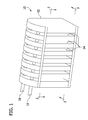
- a heat exchanger incorporating one embodiment is designated in its entirety by the reference number 10.
- the heat exchanger 10 has a casing 12 including a plurality of cold air inlets 14 for receiving cold fluid (e.g., cold air from a ram air duct), a hot fluid inlet 16 for receiving hot fluid (e.g., hot air from an air cycle system compressor), and a hot fluid outlet 18 for discharging the hot fluid after being cooled by the heat exchanger.
- the cold fluid exits the heat exchanger 10 through cold air outlets 20 ( Fig. 2 ).
- the casing 12 is made from aluminum nitride impregnated alumina-silica cloth but other materials may be used.
- the material is capable of withstanding high temperatures such as those commonly found on the outlet side of a compressor in an air cycle thermal management system on an aircraft.
- the material is NITIVY ALF alumina-silica cloth available from Nitivy Co., Ltd. of Tokyo, Japan, or Ceramacast 675N aluminum nitride available from Aremco Products Inc. of Valley Cottage, New York.
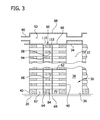
- cold fluid entering the heat exchanger 10 through the cold fluid inlets 14 travels along a cold fluid flowpath, generally designated by 30, to the corresponding cold fluid outlet 20.
- the cold fluid flowpath 30 is defined by an upstream passage 32 having a top wall 34, a bottom wall 36, an end wall 38, and opposing side walls 40.
- the top wall 34, bottom wall 36, and end wall 38 form at least a portion of the casing 12.
- the opposing side walls 40 comprise a thermally conductive ceramic foam sheet material.
- the side walls 40 comprise Boeing Rigid Insulation (BRI).
- BRI is a hyper-porous, micro-channel ceramic foam having a pore size of about 35 microns and over 31,350 square feet of internal surface area per cubic foot.
- BRI has a thermal conductivity of about 0.05 BTU/hr-ft-°R.
- BRI is available from The Boeing Company of Chicago, Illinois.
- the rigid insulation has a high surface area, providing good heat transfer to the cold fluid passing through the rigid insulation. In one embodiment the insulation has a thickness of about 0.150 inch.
- Boeing Rigid Insulation is described in more detail in US Patent 6,716,782 .
- Thermally conductive elements 60 extend through the ceramic foam walls 40 at spaced intervals.
- the thermally conductive elements 60 are made of aluminum nitride that is injected as a liquid into holes formed in the ceramic foam.
- the elements 60 are cylindrical pins or rods having a diameter of about 0.141 inch.
- the elements 60 are arranged in staggered rows. Although the elements may have another spacing, in one embodiment the elements in each row are vertically spaced about 0.49 inch apart and each row is spaced about 0.245 inch from adjacent rows. This element 60 size and spacing reduce the flow area through the porous side walls 40 by about twelve percent.
- the elements 60 span a downstream passage 62 formed between the foam side wall 40 and a thermally conductive wall 64.
- the elements 60 are connected (e.g., with aluminum nitride) to the thermally conductive wall 64.
- the thermally conductive wall 64 may be made of other materials, in one embodiment the wall is made from alumina-silica cloth impregnated with aluminum nitride.
- the downstream passage 62 also includes a top wall 66, a bottom wall 68, and an end wall 70. The top wall 66, bottom wall 68, and end wall 70 form part of the casing 12.
- a hot fluid flowpath is formed between opposing thermally conductive walls 64 and opposing end walls 82.
- a bottom wall 84 closes a lower end of the hot fluid flowpath 80.
- a porous foam panel 110 having spaced thermally conductive elements 112 distributed over the panel and extending through the panel and out from each face is positioned in the hot fluid flowpath 80 such that the conductive elements 112 are bonded to the opposing thermally conductive walls 64.
- the panel 110 may be made of other materials and have other thicknesses, in one embodiment the porous panel comprises BRI having a thickness of about 0.150 inch.
- thermally conductive elements 112 may be made of other materials, in one embodiment the thermally conductive elements are made of the same material as the thermally conductive elements 60 of the cold side. Further, the thermally conductive elements 112 of one embodiment have the same diameter and spacing as the elements 60 of the cold side. Although the elements 112 may extend beyond the panel 110 by other distances, in one embodiment the elements extend about 0.125 inch from each face.
- a dividing wall 86 extends from a top wall 88 to the bottom wall 84 on the side of the porous panel 110 open to an upstream chamber 92 but only extends to a location above the bottom wall 84 on the opposite side of the porous panel. The dividing wall 86 divides the hot fluid flowpath 80 into an inlet side 94 and an outlet side 98.
- hot fluid entering the hot fluid inlet 16 travels through tubing 90 to an upstream chamber 92.
- the hot fluid flows through an inlet 114 and downward through an upstream section 114 of the hot fluid flowpath 80.
- the hot fluid is nearly evenly distributed across the surface of the porous panel 110 due to the relatively high flow resistance of the panel.
- the hot fluid passes through the porous panel 110 and continues downward on the other side, eventually turning around a lower end 96 of the dividing wall 86.
- the hot fluid travels upward through a downstream section 98 of the hot fluid flowpath. Again, the fluid is almost evenly distributed across the surface of the porous panel 110.
- the hot fluid passes through the porous panel 110 again as it travels upward.
- the hot fluid travels through the downstream section 98, out an outlet 116, and into the downstream chamber 100. From the downstream chamber 100, the hot fluid travels through tubing 102 and out the hot fluid outlet 18. As the hot fluid travels through the hot fluid flowpath 90, heat is transferred to the cold flowpath by convection to the porous material and conduction from the porous material through the conductive elements 112 to the walls 64, and by direct convection to the conductive elements, then conduction to the walls 64, and finally, by direct convection to the walls 64 themselves.
- Cold air entering the cold air inlet 14 travels through the upstream passage 32 generally parallel to the porous side walls 40.
- a majority of cold air entering the inlet 14 turns orthogonally and travels through one of the opposing porous foam side walls 40 where it absorbs thermal energy from the BRI ceramic foam.
- This thermal energy is conducted from the wall 64 to the ceramic foam panels 40 by the thermally conductive elements 60.
- the fluid becomes rarefied when forced through the BRI, decreasing fluid friction and the associated pressure drop.
- the cold air After exiting the porous foam side walls 40, the cold air turns orthogonally again and travels through the downstream passage 62 generally parallel to the thermally conductive wall 64 where it absorbs more thermal energy by direct convective heat transfer from both the thermally conductive elements 60 and the conductive wall 64.
- the materials used can permit operation at temperatures in excess of 1000°F. These materials are also lightweight, permitting use in aircraft. Because the materials are lightweight and the heat exchanger can withstand higher temperatures, the aircraft can have more range.
- the porous side walls 40 provide large surface areas that cause air traveling through the side walls to be at a low velocity. Further, the porous side walls 40 provide a low pressure differential across the walls.
Landscapes
- Engineering & Computer Science (AREA)
- Physics & Mathematics (AREA)
- Thermal Sciences (AREA)
- Mechanical Engineering (AREA)
- General Engineering & Computer Science (AREA)
- Chemical & Material Sciences (AREA)
- Dispersion Chemistry (AREA)
- Ceramic Engineering (AREA)
- Heat-Exchange Devices With Radiators And Conduit Assemblies (AREA)
- Ceramic Products (AREA)
- Laminated Bodies (AREA)
Applications Claiming Priority (1)
| Application Number | Priority Date | Filing Date | Title |
|---|---|---|---|
| US13/309,178 US9074829B2 (en) | 2011-12-01 | 2011-12-01 | Lightweight high temperature heat exchanger |
Publications (3)
| Publication Number | Publication Date |
|---|---|
| EP2600093A2 true EP2600093A2 (de) | 2013-06-05 |
| EP2600093A3 EP2600093A3 (de) | 2015-03-18 |
| EP2600093B1 EP2600093B1 (de) | 2018-06-13 |
Family
ID=47358544
Family Applications (1)
| Application Number | Title | Priority Date | Filing Date |
|---|---|---|---|
| EP12193431.9A Not-in-force EP2600093B1 (de) | 2011-12-01 | 2012-11-20 | Leichter Hochtemperaturwärmetauscher |
Country Status (2)
| Country | Link |
|---|---|
| US (1) | US9074829B2 (de) |
| EP (1) | EP2600093B1 (de) |
Cited By (1)
| Publication number | Priority date | Publication date | Assignee | Title |
|---|---|---|---|---|
| EP3638971B1 (de) * | 2017-06-11 | 2023-09-13 | Zvi Livni | Platten- und mantelwärmeaustauschsystem mit einem geteilten verteilerrohr |
Families Citing this family (3)
| Publication number | Priority date | Publication date | Assignee | Title |
|---|---|---|---|---|
| US9182175B2 (en) * | 2011-12-01 | 2015-11-10 | The Boeing Company | Anti-icing heat exchanger |
| EP3176532B1 (de) * | 2014-07-29 | 2022-07-20 | Kyocera Corporation | Wärmetauscher |
| US10260422B2 (en) | 2016-05-06 | 2019-04-16 | United Technologies Corporation | Heat temperature gradient heat exchanger |
Citations (1)
| Publication number | Priority date | Publication date | Assignee | Title |
|---|---|---|---|---|
| US6716782B2 (en) | 2002-08-16 | 2004-04-06 | The Boeing Company | Rigid insulation and method of producing same |
Family Cites Families (22)
| Publication number | Priority date | Publication date | Assignee | Title |
|---|---|---|---|---|
| US3557557A (en) | 1969-11-24 | 1971-01-26 | Gen Motors Corp | Engine air precooler and ice eliminator |
| US4333522A (en) * | 1979-02-07 | 1982-06-08 | Heinz Brune | Casings for heat exchangers and burner/recuperator assemblies incorporating such casings |
| EP0510734A1 (de) | 1991-02-20 | 1992-10-28 | Akzo Nobel N.V. | Wärmeaustauschkörper, insbesondere zum Kühlen eines Halbleitermodules |
| US5752566A (en) | 1997-01-16 | 1998-05-19 | Ford Motor Company | High capacity condenser |
| US20080003940A1 (en) | 1998-11-09 | 2008-01-03 | Building Performance Equipment, Inc. | Ventilator system and method |
| US6203587B1 (en) * | 1999-01-19 | 2001-03-20 | International Fuel Cells Llc | Compact fuel gas reformer assemblage |
| CN1119195C (zh) | 1999-07-12 | 2003-08-27 | 吕应中 | 气体脱水方法及装置 |
| US7055781B2 (en) | 2003-06-05 | 2006-06-06 | The Boeing Company | Cooled insulation surface temperature control system |
| US7090940B2 (en) | 2003-11-05 | 2006-08-15 | Utc Fuel Cells, Llc | Freeze tolerant fuel cell power plant with a direct contact heat exchanger |
| CN100414245C (zh) * | 2003-12-22 | 2008-08-27 | 昭和电工株式会社 | 热交换器及其制造方法 |
| DE102005061599A1 (de) | 2005-12-22 | 2007-06-28 | Airbus Deutschland Gmbh | Modulares Kühlsystem und Kälteerzeugungseinrichtung für ein solches Kühlsystem |
| US7742297B2 (en) | 2006-04-20 | 2010-06-22 | The Boeing Company | Ceramic foam electronic component cooling |
| US8162035B2 (en) | 2006-04-20 | 2012-04-24 | The Boeing Company | High conductivity ceramic foam cold plate |
| US7501111B2 (en) | 2006-08-25 | 2009-03-10 | Conoco Phillips Company | Increased capacity sulfur recovery plant and process for recovering elemental sulfur |
| JP2008122058A (ja) | 2006-10-17 | 2008-05-29 | Alps Electric Co Ltd | ラジエータ及び冷却システム |
| US8191616B2 (en) * | 2006-11-02 | 2012-06-05 | The Boeing Company | Combined thermal protection and surface temperature control system |
| JP2008283067A (ja) | 2007-05-11 | 2008-11-20 | Denso Corp | Al−AlN複合材料及びその製造方法並びに熱交換器 |
| US8171986B2 (en) * | 2008-04-02 | 2012-05-08 | Northrop Grumman Systems Corporation | Foam metal heat exchanger system |
| US20090288814A1 (en) * | 2008-05-20 | 2009-11-26 | The Boeing Company. | Mixed Carbon Foam/Metallic Heat Exchanger |
| US8322406B2 (en) * | 2008-07-14 | 2012-12-04 | University Of Central Florida Research Foundation, Inc. | Thermally conductive porous element-based recuperators |
| US8720828B2 (en) | 2009-12-03 | 2014-05-13 | The Boeing Company | Extended plug cold plate |
| US9182175B2 (en) * | 2011-12-01 | 2015-11-10 | The Boeing Company | Anti-icing heat exchanger |
-
2011
- 2011-12-01 US US13/309,178 patent/US9074829B2/en not_active Expired - Fee Related
-
2012
- 2012-11-20 EP EP12193431.9A patent/EP2600093B1/de not_active Not-in-force
Patent Citations (1)
| Publication number | Priority date | Publication date | Assignee | Title |
|---|---|---|---|---|
| US6716782B2 (en) | 2002-08-16 | 2004-04-06 | The Boeing Company | Rigid insulation and method of producing same |
Cited By (1)
| Publication number | Priority date | Publication date | Assignee | Title |
|---|---|---|---|---|
| EP3638971B1 (de) * | 2017-06-11 | 2023-09-13 | Zvi Livni | Platten- und mantelwärmeaustauschsystem mit einem geteilten verteilerrohr |
Also Published As
| Publication number | Publication date |
|---|---|
| EP2600093A3 (de) | 2015-03-18 |
| EP2600093B1 (de) | 2018-06-13 |
| US9074829B2 (en) | 2015-07-07 |
| US20130140003A1 (en) | 2013-06-06 |
Similar Documents
| Publication | Publication Date | Title |
|---|---|---|
| EP2600094B1 (de) | Frostgeschützter Wärmetauscher | |
| Siddiqui et al. | Efficient energy utilization through proper design of microchannel heat exchanger manifolds: A comprehensive review | |
| Lu et al. | Heat transfer in open-cell metal foams | |
| CN106052432B (zh) | 具有交叉流道的微通道换热器 | |
| US9377250B2 (en) | Cross-flow heat exchanger having graduated fin density | |
| US9851159B2 (en) | Curved cross-flow heat exchanger | |
| US5628363A (en) | Composite continuous sheet fin heat exchanger | |
| US9638471B2 (en) | Balanced heat exchanger systems and methods | |
| US9074829B2 (en) | Lightweight high temperature heat exchanger | |
| US9682782B2 (en) | Plate-fin tubular hybrid heat exchanger design for an air and fuel cooled air cooler | |
| CN213304112U (zh) | 一种基于多孔介质的微通道散热器 | |
| US20140231048A1 (en) | Heat exchanger | |
| EP2469214B1 (de) | Oberflächenkühlungsgerät mit Kanalrippen | |
| RU2731464C2 (ru) | Теплообменник, содержащий устройство для распределения жидкостно-газовой смеси | |
| US20160377350A1 (en) | Optimized plate fin heat exchanger for improved compliance to improve thermal life | |
| CN105221269A (zh) | 燃气涡轮的介质垫 | |
| KR101405394B1 (ko) | 인쇄기판형 열교환기 | |
| US20150000874A1 (en) | Fuel oil heat exchanger utilizing heat pipes | |
| ITTO20111025A1 (it) | Serbatoio del combustibile per velivoli provvisti di sistema di riscaldamento del combustibile e sistema di riscaldamento del combustibile per velivoli provvisto di un tale serbatoio | |
| EP3455575B1 (de) | Rippe für ein geripptes gehäuse für wärmetauscher sowie wärmetauscher | |
| CN106323024A (zh) | 蒸发式冷凝器 | |
| Kotcioglu et al. | Experimental study on the heat transfer and pressure drop of a cross-flow heat exchanger with different pin–fin arrays | |
| US20230262947A1 (en) | Systems for a heat exchanger | |
| CN109635505A (zh) | 一种锯齿形翅片换热器流动传热特性预测方法 | |
| US10101093B2 (en) | Heat exchange device and method for making such a device |
Legal Events
| Date | Code | Title | Description |
|---|---|---|---|
| PUAI | Public reference made under article 153(3) epc to a published international application that has entered the european phase |
Free format text: ORIGINAL CODE: 0009012 |
|
| 17P | Request for examination filed |
Effective date: 20121120 |
|
| AK | Designated contracting states |
Kind code of ref document: A2 Designated state(s): AL AT BE BG CH CY CZ DE DK EE ES FI FR GB GR HR HU IE IS IT LI LT LU LV MC MK MT NL NO PL PT RO RS SE SI SK SM TR |
|
| AX | Request for extension of the european patent |
Extension state: BA ME |
|
| PUAL | Search report despatched |
Free format text: ORIGINAL CODE: 0009013 |
|
| AK | Designated contracting states |
Kind code of ref document: A3 Designated state(s): AL AT BE BG CH CY CZ DE DK EE ES FI FR GB GR HR HU IE IS IT LI LT LU LV MC MK MT NL NO PL PT RO RS SE SI SK SM TR |
|
| AX | Request for extension of the european patent |
Extension state: BA ME |
|
| RIC1 | Information provided on ipc code assigned before grant |
Ipc: F28F 13/00 20060101AFI20150209BHEP Ipc: F28F 21/04 20060101ALI20150209BHEP |
|
| 17Q | First examination report despatched |
Effective date: 20160504 |
|
| GRAP | Despatch of communication of intention to grant a patent |
Free format text: ORIGINAL CODE: EPIDOSNIGR1 |
|
| RIC1 | Information provided on ipc code assigned before grant |
Ipc: F28F 13/00 20060101AFI20171127BHEP |
|
| INTG | Intention to grant announced |
Effective date: 20171212 |
|
| GRAJ | Information related to disapproval of communication of intention to grant by the applicant or resumption of examination proceedings by the epo deleted |
Free format text: ORIGINAL CODE: EPIDOSDIGR1 |
|
| GRAR | Information related to intention to grant a patent recorded |
Free format text: ORIGINAL CODE: EPIDOSNIGR71 |
|
| GRAS | Grant fee paid |
Free format text: ORIGINAL CODE: EPIDOSNIGR3 |
|
| INTC | Intention to grant announced (deleted) | ||
| INTG | Intention to grant announced |
Effective date: 20180403 |
|
| GRAA | (expected) grant |
Free format text: ORIGINAL CODE: 0009210 |
|
| AK | Designated contracting states |
Kind code of ref document: B1 Designated state(s): AL AT BE BG CH CY CZ DE DK EE ES FI FR GB GR HR HU IE IS IT LI LT LU LV MC MK MT NL NO PL PT RO RS SE SI SK SM TR |
|
| REG | Reference to a national code |
Ref country code: GB Ref legal event code: FG4D |
|
| REG | Reference to a national code |
Ref country code: CH Ref legal event code: EP Ref country code: AT Ref legal event code: REF Ref document number: 1008935 Country of ref document: AT Kind code of ref document: T Effective date: 20180615 |
|
| REG | Reference to a national code |
Ref country code: IE Ref legal event code: FG4D |
|
| REG | Reference to a national code |
Ref country code: DE Ref legal event code: R096 Ref document number: 602012047376 Country of ref document: DE |
|
| REG | Reference to a national code |
Ref country code: NL Ref legal event code: MP Effective date: 20180613 |
|
| REG | Reference to a national code |
Ref country code: LT Ref legal event code: MG4D |
|
| PG25 | Lapsed in a contracting state [announced via postgrant information from national office to epo] |
Ref country code: LT Free format text: LAPSE BECAUSE OF FAILURE TO SUBMIT A TRANSLATION OF THE DESCRIPTION OR TO PAY THE FEE WITHIN THE PRESCRIBED TIME-LIMIT Effective date: 20180613 Ref country code: ES Free format text: LAPSE BECAUSE OF FAILURE TO SUBMIT A TRANSLATION OF THE DESCRIPTION OR TO PAY THE FEE WITHIN THE PRESCRIBED TIME-LIMIT Effective date: 20180613 Ref country code: FI Free format text: LAPSE BECAUSE OF FAILURE TO SUBMIT A TRANSLATION OF THE DESCRIPTION OR TO PAY THE FEE WITHIN THE PRESCRIBED TIME-LIMIT Effective date: 20180613 Ref country code: NO Free format text: LAPSE BECAUSE OF FAILURE TO SUBMIT A TRANSLATION OF THE DESCRIPTION OR TO PAY THE FEE WITHIN THE PRESCRIBED TIME-LIMIT Effective date: 20180913 Ref country code: SE Free format text: LAPSE BECAUSE OF FAILURE TO SUBMIT A TRANSLATION OF THE DESCRIPTION OR TO PAY THE FEE WITHIN THE PRESCRIBED TIME-LIMIT Effective date: 20180613 Ref country code: BG Free format text: LAPSE BECAUSE OF FAILURE TO SUBMIT A TRANSLATION OF THE DESCRIPTION OR TO PAY THE FEE WITHIN THE PRESCRIBED TIME-LIMIT Effective date: 20180913 Ref country code: CY Free format text: LAPSE BECAUSE OF FAILURE TO SUBMIT A TRANSLATION OF THE DESCRIPTION OR TO PAY THE FEE WITHIN THE PRESCRIBED TIME-LIMIT Effective date: 20180613 |
|
| PG25 | Lapsed in a contracting state [announced via postgrant information from national office to epo] |
Ref country code: HR Free format text: LAPSE BECAUSE OF FAILURE TO SUBMIT A TRANSLATION OF THE DESCRIPTION OR TO PAY THE FEE WITHIN THE PRESCRIBED TIME-LIMIT Effective date: 20180613 Ref country code: RS Free format text: LAPSE BECAUSE OF FAILURE TO SUBMIT A TRANSLATION OF THE DESCRIPTION OR TO PAY THE FEE WITHIN THE PRESCRIBED TIME-LIMIT Effective date: 20180613 Ref country code: GR Free format text: LAPSE BECAUSE OF FAILURE TO SUBMIT A TRANSLATION OF THE DESCRIPTION OR TO PAY THE FEE WITHIN THE PRESCRIBED TIME-LIMIT Effective date: 20180914 Ref country code: LV Free format text: LAPSE BECAUSE OF FAILURE TO SUBMIT A TRANSLATION OF THE DESCRIPTION OR TO PAY THE FEE WITHIN THE PRESCRIBED TIME-LIMIT Effective date: 20180613 |
|
| REG | Reference to a national code |
Ref country code: AT Ref legal event code: MK05 Ref document number: 1008935 Country of ref document: AT Kind code of ref document: T Effective date: 20180613 |
|
| PG25 | Lapsed in a contracting state [announced via postgrant information from national office to epo] |
Ref country code: NL Free format text: LAPSE BECAUSE OF FAILURE TO SUBMIT A TRANSLATION OF THE DESCRIPTION OR TO PAY THE FEE WITHIN THE PRESCRIBED TIME-LIMIT Effective date: 20180613 |
|
| PG25 | Lapsed in a contracting state [announced via postgrant information from national office to epo] |
Ref country code: IS Free format text: LAPSE BECAUSE OF FAILURE TO SUBMIT A TRANSLATION OF THE DESCRIPTION OR TO PAY THE FEE WITHIN THE PRESCRIBED TIME-LIMIT Effective date: 20181013 Ref country code: EE Free format text: LAPSE BECAUSE OF FAILURE TO SUBMIT A TRANSLATION OF THE DESCRIPTION OR TO PAY THE FEE WITHIN THE PRESCRIBED TIME-LIMIT Effective date: 20180613 Ref country code: AT Free format text: LAPSE BECAUSE OF FAILURE TO SUBMIT A TRANSLATION OF THE DESCRIPTION OR TO PAY THE FEE WITHIN THE PRESCRIBED TIME-LIMIT Effective date: 20180613 Ref country code: RO Free format text: LAPSE BECAUSE OF FAILURE TO SUBMIT A TRANSLATION OF THE DESCRIPTION OR TO PAY THE FEE WITHIN THE PRESCRIBED TIME-LIMIT Effective date: 20180613 Ref country code: SK Free format text: LAPSE BECAUSE OF FAILURE TO SUBMIT A TRANSLATION OF THE DESCRIPTION OR TO PAY THE FEE WITHIN THE PRESCRIBED TIME-LIMIT Effective date: 20180613 Ref country code: PL Free format text: LAPSE BECAUSE OF FAILURE TO SUBMIT A TRANSLATION OF THE DESCRIPTION OR TO PAY THE FEE WITHIN THE PRESCRIBED TIME-LIMIT Effective date: 20180613 Ref country code: CZ Free format text: LAPSE BECAUSE OF FAILURE TO SUBMIT A TRANSLATION OF THE DESCRIPTION OR TO PAY THE FEE WITHIN THE PRESCRIBED TIME-LIMIT Effective date: 20180613 |
|
| PG25 | Lapsed in a contracting state [announced via postgrant information from national office to epo] |
Ref country code: SM Free format text: LAPSE BECAUSE OF FAILURE TO SUBMIT A TRANSLATION OF THE DESCRIPTION OR TO PAY THE FEE WITHIN THE PRESCRIBED TIME-LIMIT Effective date: 20180613 Ref country code: IT Free format text: LAPSE BECAUSE OF FAILURE TO SUBMIT A TRANSLATION OF THE DESCRIPTION OR TO PAY THE FEE WITHIN THE PRESCRIBED TIME-LIMIT Effective date: 20180613 |
|
| REG | Reference to a national code |
Ref country code: DE Ref legal event code: R097 Ref document number: 602012047376 Country of ref document: DE |
|
| PLBE | No opposition filed within time limit |
Free format text: ORIGINAL CODE: 0009261 |
|
| STAA | Information on the status of an ep patent application or granted ep patent |
Free format text: STATUS: NO OPPOSITION FILED WITHIN TIME LIMIT |
|
| 26N | No opposition filed |
Effective date: 20190314 |
|
| PG25 | Lapsed in a contracting state [announced via postgrant information from national office to epo] |
Ref country code: DK Free format text: LAPSE BECAUSE OF FAILURE TO SUBMIT A TRANSLATION OF THE DESCRIPTION OR TO PAY THE FEE WITHIN THE PRESCRIBED TIME-LIMIT Effective date: 20180613 Ref country code: SI Free format text: LAPSE BECAUSE OF FAILURE TO SUBMIT A TRANSLATION OF THE DESCRIPTION OR TO PAY THE FEE WITHIN THE PRESCRIBED TIME-LIMIT Effective date: 20180613 |
|
| REG | Reference to a national code |
Ref country code: CH Ref legal event code: PL |
|
| PG25 | Lapsed in a contracting state [announced via postgrant information from national office to epo] |
Ref country code: LU Free format text: LAPSE BECAUSE OF NON-PAYMENT OF DUE FEES Effective date: 20181120 Ref country code: MC Free format text: LAPSE BECAUSE OF FAILURE TO SUBMIT A TRANSLATION OF THE DESCRIPTION OR TO PAY THE FEE WITHIN THE PRESCRIBED TIME-LIMIT Effective date: 20180613 |
|
| REG | Reference to a national code |
Ref country code: BE Ref legal event code: MM Effective date: 20181130 |
|
| REG | Reference to a national code |
Ref country code: IE Ref legal event code: MM4A |
|
| PG25 | Lapsed in a contracting state [announced via postgrant information from national office to epo] |
Ref country code: LI Free format text: LAPSE BECAUSE OF NON-PAYMENT OF DUE FEES Effective date: 20181130 Ref country code: CH Free format text: LAPSE BECAUSE OF NON-PAYMENT OF DUE FEES Effective date: 20181130 |
|
| PG25 | Lapsed in a contracting state [announced via postgrant information from national office to epo] |
Ref country code: IE Free format text: LAPSE BECAUSE OF NON-PAYMENT OF DUE FEES Effective date: 20181120 |
|
| PG25 | Lapsed in a contracting state [announced via postgrant information from national office to epo] |
Ref country code: BE Free format text: LAPSE BECAUSE OF NON-PAYMENT OF DUE FEES Effective date: 20181130 Ref country code: AL Free format text: LAPSE BECAUSE OF FAILURE TO SUBMIT A TRANSLATION OF THE DESCRIPTION OR TO PAY THE FEE WITHIN THE PRESCRIBED TIME-LIMIT Effective date: 20180613 |
|
| PG25 | Lapsed in a contracting state [announced via postgrant information from national office to epo] |
Ref country code: MT Free format text: LAPSE BECAUSE OF NON-PAYMENT OF DUE FEES Effective date: 20181120 |
|
| PG25 | Lapsed in a contracting state [announced via postgrant information from national office to epo] |
Ref country code: TR Free format text: LAPSE BECAUSE OF FAILURE TO SUBMIT A TRANSLATION OF THE DESCRIPTION OR TO PAY THE FEE WITHIN THE PRESCRIBED TIME-LIMIT Effective date: 20180613 |
|
| PG25 | Lapsed in a contracting state [announced via postgrant information from national office to epo] |
Ref country code: PT Free format text: LAPSE BECAUSE OF FAILURE TO SUBMIT A TRANSLATION OF THE DESCRIPTION OR TO PAY THE FEE WITHIN THE PRESCRIBED TIME-LIMIT Effective date: 20180613 |
|
| PG25 | Lapsed in a contracting state [announced via postgrant information from national office to epo] |
Ref country code: HU Free format text: LAPSE BECAUSE OF FAILURE TO SUBMIT A TRANSLATION OF THE DESCRIPTION OR TO PAY THE FEE WITHIN THE PRESCRIBED TIME-LIMIT; INVALID AB INITIO Effective date: 20121120 Ref country code: MK Free format text: LAPSE BECAUSE OF NON-PAYMENT OF DUE FEES Effective date: 20180613 |
|
| PGFP | Annual fee paid to national office [announced via postgrant information from national office to epo] |
Ref country code: DE Payment date: 20211126 Year of fee payment: 10 Ref country code: FR Payment date: 20211124 Year of fee payment: 10 Ref country code: GB Payment date: 20211129 Year of fee payment: 10 |
|
| REG | Reference to a national code |
Ref country code: DE Ref legal event code: R119 Ref document number: 602012047376 Country of ref document: DE |
|
| GBPC | Gb: european patent ceased through non-payment of renewal fee |
Effective date: 20221120 |
|
| PG25 | Lapsed in a contracting state [announced via postgrant information from national office to epo] |
Ref country code: GB Free format text: LAPSE BECAUSE OF NON-PAYMENT OF DUE FEES Effective date: 20221120 Ref country code: DE Free format text: LAPSE BECAUSE OF NON-PAYMENT OF DUE FEES Effective date: 20230601 |
|
| PG25 | Lapsed in a contracting state [announced via postgrant information from national office to epo] |
Ref country code: FR Free format text: LAPSE BECAUSE OF NON-PAYMENT OF DUE FEES Effective date: 20221130 |