EP2600129A2 - Capteur de couple - Google Patents
Capteur de couple Download PDFInfo
- Publication number
- EP2600129A2 EP2600129A2 EP12168924.4A EP12168924A EP2600129A2 EP 2600129 A2 EP2600129 A2 EP 2600129A2 EP 12168924 A EP12168924 A EP 12168924A EP 2600129 A2 EP2600129 A2 EP 2600129A2
- Authority
- EP
- European Patent Office
- Prior art keywords
- housing
- collector
- magnet
- index sensor
- torque index
- Prior art date
- Legal status (The legal status is an assumption and is not a legal conclusion. Google has not performed a legal analysis and makes no representation as to the accuracy of the status listed.)
- Ceased
Links
Images

Classifications
-
- G—PHYSICS
- G01—MEASURING; TESTING
- G01L—MEASURING FORCE, STRESS, TORQUE, WORK, MECHANICAL POWER, MECHANICAL EFFICIENCY, OR FLUID PRESSURE
- G01L3/00—Measuring torque, work, mechanical power, or mechanical efficiency, in general
- G01L3/02—Rotary-transmission dynamometers
- G01L3/04—Rotary-transmission dynamometers wherein the torque-transmitting element comprises a torsionally-flexible shaft
- G01L3/10—Rotary-transmission dynamometers wherein the torque-transmitting element comprises a torsionally-flexible shaft involving electric or magnetic means for indicating
- G01L3/101—Rotary-transmission dynamometers wherein the torque-transmitting element comprises a torsionally-flexible shaft involving electric or magnetic means for indicating involving magnetic or electromagnetic means
- G01L3/104—Rotary-transmission dynamometers wherein the torque-transmitting element comprises a torsionally-flexible shaft involving electric or magnetic means for indicating involving magnetic or electromagnetic means involving permanent magnets
-
- B—PERFORMING OPERATIONS; TRANSPORTING
- B62—LAND VEHICLES FOR TRAVELLING OTHERWISE THAN ON RAILS
- B62D—MOTOR VEHICLES; TRAILERS
- B62D6/00—Arrangements for automatically controlling steering depending on driving conditions sensed and responded to, e.g. control circuits
- B62D6/08—Arrangements for automatically controlling steering depending on driving conditions sensed and responded to, e.g. control circuits responsive only to driver input torque
- B62D6/10—Arrangements for automatically controlling steering depending on driving conditions sensed and responded to, e.g. control circuits responsive only to driver input torque characterised by means for sensing or determining torque
Definitions
- the present disclosure relates to a torque index sensor.
- the electric power-assist steering system generates an assist force based on the steering torque and the steering angle, so as to enhance the steering performance of the vehicle.
- a steering system that assists a steering force of a vehicle with a separate power is used to enhance the motion stability of a vehicle.
- the auxiliary steering device uses hydraulic pressure, but an Electronic Power Steering (EPS) system adapted to transmit a rotation output of an electric motor to a steering shaft via a speed reduction mechanism has been increasingly employed these days from a viewpoint of a reduction in engine load, a reduction in weight, an enhanced steering stability and a quick restoring force.
- EPS Electronic Power Steering
- the EPS system is such that an Electronic Control Unit (ECU) drives a motor in response to steering conditions detected by a speed sensor, a torque angle sensor and a torque index sensor to enhance a steering stability and provide a quick restoring force, whereby a driver can safely steer a vehicle.
- ECU Electronic Control Unit
- TAS Torque Angle Sensor
- TAS Torque Index Sensor
- TIS entitled as "torque sensor arrangement with rotational angle index detection” is disclosed in Korean Laid-Open Patent No.: 2011-0041468 , where the sensor arrangement comprises a torque sensor for measuring a torque acting on a first shaft, wherein the sensor arrangement further comprises a rotational angle index unit that is adapted to detect and/or a defined rotational angle and/or a defined rotational angle range.
- the torque sensor thus described is provided with a collector as a part for concentrating a magnetic flux of a magnet.
- the collector is secured at a housing, and if a coupling between the collector and the housing is loosened, a distance between the collector and the housing may become uneven to generate an error in a measured value of the sensor.
- EPS Electronic Power Steering
- the present disclosure is directed to cope with the abovementioned problems/disadvantages and it is an object of the present disclosure to provide a torque index sensor improved in structure configured to tightly fix a collector even at a high temperature and to prevent the collector from being disengaged.
- a torque index sensor comprising: a housing; a stator mounted at a space inside the housing; a magnet arranged inside the stator to rotate with a rotation shaft; a PCB (Printed Circuit Board) fixedly mounted inside the housing and mounted with a first magnetic element outputting a magnetization signal in response to rotation of the magnet; at least one or more fixing bosses protrusively formed at the housing; and a collector having a plurality of through holes penetratively formed at a position corresponding to that of the fixing boss and concentrating a magnetic field for guiding a magnetic flux of the magnet, wherein the fixing boss is thermally fused after passing the through hole to tightly fix the collector at an inner surface of the housing.
- PCB Print Circuit Board
- the collector includes at least one or more through holes.
- two collectors in a pair, are vertically and symmetrically mounted at an inner surface of the housing about the first magnetic element.
- the collector is brought into contact at a distal end with the first magnetic element.
- the PCB further includes a second magnetic element detecting an index magnet mounted at the rotation shaft.
- the through holes, in a pair are symmetrically formed based on an imaginary line passing a weight center of the collector.
- the through hole is formed at an area surface-contacted to the housing coupled by the collector.
- the torque index sensor according to the present disclosure has an advantageous effect in that a fixing boss protrusively formed at an inner side of a housing is thermally fused after passing a through hole formed at a collector, such that even if the torque index sensor is used for a long time at a high temperature, the collector is prevented from being disengaged and is tightly fixed to the housing to enhance a product reliability.
- the terms “substantially” and “approximately” provide an industry-accepted tolerance for its corresponding term and/or relativity between items. Such an industry-accepted tolerance ranges from less than one percent to ten percent and corresponds to, but is not limited to, component values, angles, et cetera.
- FIG.1 is a schematic perspective view illustrating essential parts of a torque index sensor according to an exemplary embodiment of the present disclosure
- FIG.2 is a plan view of FIG. 1
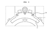
- FIG.3 is an enlarged schematic view that illustrates an essential part of FIG.2 .
- a torque index sensor includes a housing (1), a stator (10), a magnet (20) and a PCB (Printed Circuit Board), where the housing (1) is protrusively formed with at least one or more fixing bosses (2), and the stator (10) is provided with a collector (11) having a through hole (12) penetratively coupled by the fixing boss (2).
- the housing (1) is protrusively formed with at least one or more fixing bosses (2)
- the stator (10) is provided with a collector (11) having a through hole (12) penetratively coupled by the fixing boss (2).
- the housing (1) forms an external look of the torque index sensor in resin material, but the material is not limited thereto and any material that has a high durability including a metal material will do.
- the housing (1) mountable on a rotation shaft (not shown) of a steering wheel is fixedly arranged regardless of and without causing any hindrance to rotation of the rotation shaft.
- the housing (1) is protrusively formed at an inner lateral surface with a plurality of fixing bosses (2), preferably at least two fixing bosses. Although not illustrated, one fixing boss (2) and two fixing bosses (2) each at a distal end of the inner lateral surface may be formed.
- the stator (10) is provided in a tooth shape.
- the stator (10) is also provided at a distal end with the collector (11) for effectively collecting a magnetic field of the magnet (20).
- Each of the collectors (11) is symmetrically arranged at an upper side and a bottom side of the stator (10) as shown in FIG.1 .
- the collector (11) serves to concentrate the magnetic field by guiding the magnetic flux of the magnet (20).
- the collector (11) is formed at an area corresponding to that of the fixing boss (2) with a plurality of through holes (12).
- two through holes (12) are provided.
- a plurality of through holes (12) be formed at an area surface-contacted by the housing (1), and symmetrically formed about the collector (11).
- the fixing boss (2) is thermally fused after passing through the through hole (12) to form a screw head-shaped head (2a), as shown in FIG. 3 .
- the head (2a) presses the collector (11) toward an inner lateral surface of the housing (1) to tightly secure the collector (11) to the housing (1). That is, in a case the fixing boss (2) having passed the through hole (12) is hot-pressed, the resin-materialed fixing boss (2) is flatly pressed to form the head (2a) and to be tightly brought into contact with the collector (11).
- the head (2a) is fixed in a surface-contacted state by pressing the collector (11) to the inner lateral surface of the housing (1).
- the magnet (20) is provided in a ring shape, mounted at an inner wall surface of the stator (10) and rotates in association with rotation of the rotation shaft (not shown) of the steering wheel.
- the PCB (30) is formed with a first magnetic element (31) detecting a torque signal of the rotation shaft rotating in association with the steering wheel by detecting the magnetic force of the magnet (30).
- the first magnetic element (31) generally includes a pair of linear Hall ICs.
- the PCB (30) is preferably arranged at an outmost area of the torque index sensor, as illustrated in FIG.1 .
- an index magnet (40) may be further mounted for receiving a rotation signal of the rotation shaft (not shown) as shown in FIG.1 , if need arises.
- the index magnet (40) is installed at a magnet holder mounted at the rotation shaft and changed in position in response to the rotation of the rotation shaft.
- the PCB (30) may be formed with a second magnetic element (32) for detecting the magnetic field of the magnet (40).
- the second magnetic element (32) functions to detect rotation of the index magnet (40) using a pulse signal and output an index pulse signal for calculating a steering angle of the rotation shaft.
- the second magnetic element (32) is provided as a Hall switch to output the index pulse signal.
- the torque index sensor thus configured according to the exemplary embodiment of the present disclosure has an industrial applicability in that a fixing boss (2) protrusively and integrally formed at an inner side of a housing (1) is thermally fused after passing a through hole (12) penetratively formed at a collector (11) to fixedly secure the collector (11) to the housing (1), such that, even if the torque index sensor is used for a long time at a high temperature, the collector (11) can be prevented from being disengaged and tightly fixed to the housing (1) enhance a product reliability, whereby the collector (11) and the magnet (20) can maintain a predetermined distance at all times to enhance reliability of a measurement value of the sensor.
- the collector (11) can be pressed to the housing (1) side with as much pressure as a contact area between the head (2a) and the collector (11), whereby a much tighter coupling can be kept.
Landscapes
- Physics & Mathematics (AREA)
- General Physics & Mathematics (AREA)
- Electromagnetism (AREA)
- Engineering & Computer Science (AREA)
- Chemical & Material Sciences (AREA)
- Combustion & Propulsion (AREA)
- Transportation (AREA)
- Mechanical Engineering (AREA)
- Power Steering Mechanism (AREA)
- Force Measurement Appropriate To Specific Purposes (AREA)
- Measurement Of Length, Angles, Or The Like Using Electric Or Magnetic Means (AREA)
Applications Claiming Priority (1)
| Application Number | Priority Date | Filing Date | Title |
|---|---|---|---|
| KR1020110125601A KR101863780B1 (ko) | 2011-11-29 | 2011-11-29 | 토크 센서 |
Publications (2)
| Publication Number | Publication Date |
|---|---|
| EP2600129A2 true EP2600129A2 (fr) | 2013-06-05 |
| EP2600129A3 EP2600129A3 (fr) | 2014-01-29 |
Family
ID=46197042
Family Applications (1)
| Application Number | Title | Priority Date | Filing Date |
|---|---|---|---|
| EP12168924.4A Ceased EP2600129A3 (fr) | 2011-11-29 | 2012-05-22 | Capteur de couple |
Country Status (5)
| Country | Link |
|---|---|
| US (1) | US8939038B2 (fr) |
| EP (1) | EP2600129A3 (fr) |
| JP (1) | JP6042667B2 (fr) |
| KR (1) | KR101863780B1 (fr) |
| CN (1) | CN103134628B (fr) |
Cited By (7)
| Publication number | Priority date | Publication date | Assignee | Title |
|---|---|---|---|---|
| DE102013006379A1 (de) * | 2013-04-13 | 2014-10-16 | Valeo Schalter Und Sensoren Gmbh | Sensorvorrichtung mit einer Drehmomentsensoreinrichtung und einer Inkrementalsensoreinrichtung und Kraftfahrzeug |
| EP2833110A1 (fr) * | 2013-08-02 | 2015-02-04 | Jtekt Corporation | Dispositif de détection de couple et système à direction assistée électrique |
| EP2924407A1 (fr) * | 2014-03-27 | 2015-09-30 | Showa Corporation | Unité de capteur, détecteur de couple et dispositif de direction assistée électrique |
| WO2018001412A1 (fr) * | 2016-06-27 | 2018-01-04 | Schaeffler Technologies AG & Co. KG | Ensemble de capteurs de position d'un rotor muni d'un agencement de capteurs et système de débrayage |
| EP3198230A4 (fr) * | 2014-09-26 | 2018-05-16 | Bourns, Inc. | Système et procédé pour équilibrage actif/annulation active de l'interférence magnétique dans un capteur magnétique |
| EP3241721A4 (fr) * | 2014-12-30 | 2018-11-14 | LG Innotek Co., Ltd. | Module de capteur de couple et dispositif de détection d'angle de direction le comprenant |
| EP3660479A4 (fr) * | 2017-07-24 | 2021-04-21 | LG Innotek Co., Ltd. | Capteur de couple |
Families Citing this family (8)
| Publication number | Priority date | Publication date | Assignee | Title |
|---|---|---|---|---|
| DE102012021137A1 (de) * | 2012-10-27 | 2014-04-30 | Valeo Schalter Und Sensoren Gmbh | Sensoreinrichtung für ein Kraftfahrzeug, Kraftfahrzeug und Verfahren zum Erstellen einer Sensoreinrichtung |
| KR102142532B1 (ko) * | 2014-01-08 | 2020-08-07 | 엘지이노텍 주식회사 | 토크 센서 |
| EP3564096B1 (fr) | 2016-12-28 | 2022-12-21 | LG Innotek Co., Ltd. | Capteur de couple et appareil de direction le comprenant |
| KR102363168B1 (ko) * | 2017-04-25 | 2022-02-15 | 엘지이노텍 주식회사 | 센싱장치 |
| JP7124566B2 (ja) * | 2018-08-29 | 2022-08-24 | 株式会社ジェイテクト | センサ装置 |
| FR3093181B1 (fr) | 2019-02-25 | 2021-05-07 | Moving Magnet Tech | Capteur de position, notamment destiné à la détection de la torsion d'une colonne de direction. |
| US20230038153A1 (en) * | 2019-12-23 | 2023-02-09 | Lg Innotek Co., Ltd. | Sensing device |
| CN114235243A (zh) * | 2021-12-31 | 2022-03-25 | 国太阳科技有限公司 | 一种汽车电动助力转向系统中的扭矩传感器 |
Citations (1)
| Publication number | Priority date | Publication date | Assignee | Title |
|---|---|---|---|---|
| KR20110041468A (ko) | 2008-07-14 | 2011-04-21 | 콘티넨탈 테베스 아게 운트 코. 오하게 | 회전 각 인덱스 검출을 갖는 토크 센서 장치 |
Family Cites Families (28)
| Publication number | Priority date | Publication date | Assignee | Title |
|---|---|---|---|---|
| DE10226062A1 (de) * | 2002-06-12 | 2004-01-08 | Ab Elektronik Gmbh | Weitwinkel-Drehwinkelsensor |
| JP2004093183A (ja) * | 2002-08-29 | 2004-03-25 | Unisia Jkc Steering System Co Ltd | 電動パワーステアリング用トルクセンサ |
| EP1706716B1 (fr) * | 2004-01-20 | 2011-09-14 | Valeo Schalter und Sensoren GmbH | Dispositif pour determiner un angle de braquage et un couple de rotation exerce sur un arbre de direction |
| JP4738889B2 (ja) * | 2005-05-24 | 2011-08-03 | 日立オートモティブシステムズ株式会社 | トルクセンサ |
| CN101341383A (zh) * | 2005-10-21 | 2009-01-07 | 石通瑞吉控制装置公司 | 包括磁化轴的传感器系统 |
| JP4871014B2 (ja) * | 2006-04-24 | 2012-02-08 | カヤバ工業株式会社 | トルクセンサ |
| JP5183036B2 (ja) * | 2006-06-23 | 2013-04-17 | 株式会社ジェイテクト | トルク検出装置及びヨーク組立体の製造方法 |
| JP4978774B2 (ja) * | 2006-11-08 | 2012-07-18 | アイシン精機株式会社 | 回転角検出装置の実装構造 |
| JP4273363B2 (ja) * | 2006-11-21 | 2009-06-03 | 日立金属株式会社 | 回転角度検出装置、回転機、及び回転角度検出法 |
| EP2136212A4 (fr) * | 2007-03-28 | 2012-07-25 | Ntn Toyo Bearing Co Ltd | Capteur de rotation |
| US8015885B2 (en) * | 2007-03-29 | 2011-09-13 | Jtekt Corporation | Torque detector |
| KR101272702B1 (ko) * | 2007-07-07 | 2013-06-10 | 엘지이노텍 주식회사 | 토크 측정장치 |
| US7855740B2 (en) * | 2007-07-20 | 2010-12-21 | Eastman Kodak Company | Multiple component readout of image sensor |
| FR2919385B1 (fr) * | 2007-07-24 | 2009-10-09 | Moving Magnet Tech Mmt | Capteur magnetique sans contact de position absolue multitour a arbre traversant |
| KR20090002543U (ko) * | 2007-09-10 | 2009-03-13 | 엘지이노텍 주식회사 | 토크 측정장치 |
| KR20090003513U (ko) * | 2007-10-11 | 2009-04-15 | 엘지이노텍 주식회사 | 토크 측정장치 |
| KR101509509B1 (ko) * | 2008-06-11 | 2015-04-08 | 엘지이노텍 주식회사 | 토크 측정장치 |
| KR101506732B1 (ko) * | 2008-08-19 | 2015-03-27 | 엘지이노텍 주식회사 | 조향용 복합센싱장치 |
| DE102008042791A1 (de) * | 2008-10-13 | 2010-04-15 | Robert Bosch Gmbh | Vorrichtung zur Erfassung eines Drehwinkels eines drehbaren Teils |
| JP5513838B2 (ja) * | 2009-10-21 | 2014-06-04 | カヤバ工業株式会社 | パワーステアリング装置 |
| KR101650457B1 (ko) * | 2009-11-20 | 2016-08-23 | 엘지이노텍 주식회사 | 차량의 조향토크 및 조향각 검출장치 |
| DE102009047222A1 (de) * | 2009-11-27 | 2011-06-01 | Robert Bosch Gmbh | Sensoranordnung zum Ermitteln eines Drehmoments und zur Indexerkennung |
| FR2953805B1 (fr) * | 2009-12-15 | 2011-12-30 | Ratier Figeac Soc | Dispositif de pilotage d'un aeronef a elements magneto-sensibles de detection de position angulaire montes hors axe |
| JP5513902B2 (ja) * | 2010-01-12 | 2014-06-04 | カヤバ工業株式会社 | トルクセンサ |
| KR101633127B1 (ko) * | 2010-03-30 | 2016-06-24 | 엘지이노텍 주식회사 | 토크 측정장치 |
| KR20120027658A (ko) * | 2010-09-13 | 2012-03-22 | 엘지이노텍 주식회사 | 토크 인덱스 센서 |
| US8448528B2 (en) * | 2010-09-27 | 2013-05-28 | Bourns Incorporated | Three-piece torque sensor assembly |
| KR101814804B1 (ko) * | 2011-04-15 | 2018-01-30 | 엘지이노텍 주식회사 | 토크 센서 |
-
2011
- 2011-11-29 KR KR1020110125601A patent/KR101863780B1/ko active Active
-
2012
- 2012-05-22 EP EP12168924.4A patent/EP2600129A3/fr not_active Ceased
- 2012-05-30 US US13/483,911 patent/US8939038B2/en active Active
- 2012-09-06 JP JP2012195963A patent/JP6042667B2/ja active Active
- 2012-11-28 CN CN201210496297.6A patent/CN103134628B/zh active Active
Patent Citations (1)
| Publication number | Priority date | Publication date | Assignee | Title |
|---|---|---|---|---|
| KR20110041468A (ko) | 2008-07-14 | 2011-04-21 | 콘티넨탈 테베스 아게 운트 코. 오하게 | 회전 각 인덱스 검출을 갖는 토크 센서 장치 |
Cited By (12)
| Publication number | Priority date | Publication date | Assignee | Title |
|---|---|---|---|---|
| DE102013006379A1 (de) * | 2013-04-13 | 2014-10-16 | Valeo Schalter Und Sensoren Gmbh | Sensorvorrichtung mit einer Drehmomentsensoreinrichtung und einer Inkrementalsensoreinrichtung und Kraftfahrzeug |
| EP2833110A1 (fr) * | 2013-08-02 | 2015-02-04 | Jtekt Corporation | Dispositif de détection de couple et système à direction assistée électrique |
| US9255857B2 (en) | 2013-08-02 | 2016-02-09 | Jtekt Corporation | Torque detecting device and electric power steering system |
| EP2924407A1 (fr) * | 2014-03-27 | 2015-09-30 | Showa Corporation | Unité de capteur, détecteur de couple et dispositif de direction assistée électrique |
| US9459165B2 (en) | 2014-03-27 | 2016-10-04 | Showa Corporation | Sensor unit, torque detector, and electric power steering device |
| EP3198230A4 (fr) * | 2014-09-26 | 2018-05-16 | Bourns, Inc. | Système et procédé pour équilibrage actif/annulation active de l'interférence magnétique dans un capteur magnétique |
| EP3198230B1 (fr) * | 2014-09-26 | 2023-04-12 | Bourns, Inc. | Système et procédé pour équilibrage actif/annulation active de l'interférence magnétique dans un capteur magnétique |
| EP3241721A4 (fr) * | 2014-12-30 | 2018-11-14 | LG Innotek Co., Ltd. | Module de capteur de couple et dispositif de détection d'angle de direction le comprenant |
| US10345166B2 (en) | 2014-12-30 | 2019-07-09 | Lg Innotek Co., Ltd. | Torque angle sensor module and apparatus for sensing steering angle of vehicle using the same |
| WO2018001412A1 (fr) * | 2016-06-27 | 2018-01-04 | Schaeffler Technologies AG & Co. KG | Ensemble de capteurs de position d'un rotor muni d'un agencement de capteurs et système de débrayage |
| EP3660479A4 (fr) * | 2017-07-24 | 2021-04-21 | LG Innotek Co., Ltd. | Capteur de couple |
| US11958555B2 (en) | 2017-07-24 | 2024-04-16 | Lg Innotek Co., Ltd. | Torque sensor |
Also Published As
| Publication number | Publication date |
|---|---|
| CN103134628A (zh) | 2013-06-05 |
| KR101863780B1 (ko) | 2018-06-01 |
| KR20130059565A (ko) | 2013-06-07 |
| EP2600129A3 (fr) | 2014-01-29 |
| US20130133437A1 (en) | 2013-05-30 |
| US8939038B2 (en) | 2015-01-27 |
| JP2013113845A (ja) | 2013-06-10 |
| CN103134628B (zh) | 2017-11-24 |
| JP6042667B2 (ja) | 2016-12-14 |
Similar Documents
| Publication | Publication Date | Title |
|---|---|---|
| US8939038B2 (en) | Torque sensor | |
| US9400290B2 (en) | Torque index sensor | |
| EP2664906B1 (fr) | Capteur d'angle de couple | |
| JP5580427B2 (ja) | 操向トルク及び操向角測定装置並びにこれを備えた車両用操向装置 | |
| KR102288523B1 (ko) | 토크센서모듈 및 이를 포함하는 조향각 센싱장치 | |
| KR20120004031A (ko) | 토크앵글센서 | |
| KR101778301B1 (ko) | 토크앵글센서 | |
| KR102142532B1 (ko) | 토크 센서 | |
| KR101884229B1 (ko) | 토크센서 | |
| JP7546460B2 (ja) | トルク・角度センサ | |
| KR20160121896A (ko) | 토크센서모듈 및 이를 포함하는 조향각 센싱장치 | |
| KR101730547B1 (ko) | 토크 앵글 센서모듈 | |
| US20240255310A1 (en) | Sensing apparatus | |
| KR20120133404A (ko) | 토크앵글센서 | |
| KR101859768B1 (ko) | 토크 인덱스 서브 앵글 센서 | |
| KR102050724B1 (ko) | 토크 앵글 센서용 기판 및 이를 갖는 토크 앵글 센서 | |
| KR101787912B1 (ko) | 센싱 조립체 | |
| KR101968509B1 (ko) | 토크 센서 | |
| KR20150018282A (ko) | 토크앵글센서 | |
| KR20130044417A (ko) | 토크 인덱스 센서 | |
| KR20130012445A (ko) | Eps모터의 센싱 마그네트 결합구조 | |
| KR20130064234A (ko) | 토크 센서 | |
| KR20160081137A (ko) | 토크센서모듈 및 이를 포함하는 조향각 센싱장치 | |
| KR20100003915U (ko) | 토크 앵글 센서 모듈의 인쇄회로기판 | |
| KR20130011663A (ko) | Eps모터의 센싱 마그네트 결합구조 |
Legal Events
| Date | Code | Title | Description |
|---|---|---|---|
| PUAI | Public reference made under article 153(3) epc to a published international application that has entered the european phase |
Free format text: ORIGINAL CODE: 0009012 |
|
| AK | Designated contracting states |
Kind code of ref document: A2 Designated state(s): AL AT BE BG CH CY CZ DE DK EE ES FI FR GB GR HR HU IE IS IT LI LT LU LV MC MK MT NL NO PL PT RO RS SE SI SK SM TR |
|
| AX | Request for extension of the european patent |
Extension state: BA ME |
|
| PUAL | Search report despatched |
Free format text: ORIGINAL CODE: 0009013 |
|
| AK | Designated contracting states |
Kind code of ref document: A3 Designated state(s): AL AT BE BG CH CY CZ DE DK EE ES FI FR GB GR HR HU IE IS IT LI LT LU LV MC MK MT NL NO PL PT RO RS SE SI SK SM TR |
|
| AX | Request for extension of the european patent |
Extension state: BA ME |
|
| RIC1 | Information provided on ipc code assigned before grant |
Ipc: G01L 3/10 20060101AFI20131220BHEP |
|
| 17P | Request for examination filed |
Effective date: 20140715 |
|
| RBV | Designated contracting states (corrected) |
Designated state(s): AL AT BE BG CH CY CZ DE DK EE ES FI FR GB GR HR HU IE IS IT LI LT LU LV MC MK MT NL NO PL PT RO RS SE SI SK SM TR |
|
| 17Q | First examination report despatched |
Effective date: 20141203 |
|
| STAA | Information on the status of an ep patent application or granted ep patent |
Free format text: STATUS: THE APPLICATION HAS BEEN REFUSED |
|
| 18R | Application refused |
Effective date: 20160408 |