EP2600138A1 - Dispositif de détection et procédé de détection pour interaction intermoléculaire - Google Patents
Dispositif de détection et procédé de détection pour interaction intermoléculaire Download PDFInfo
- Publication number
- EP2600138A1 EP2600138A1 EP11812146.6A EP11812146A EP2600138A1 EP 2600138 A1 EP2600138 A1 EP 2600138A1 EP 11812146 A EP11812146 A EP 11812146A EP 2600138 A1 EP2600138 A1 EP 2600138A1
- Authority
- EP
- European Patent Office
- Prior art keywords
- white light
- light
- spectrometer
- detector
- transmission path
- Prior art date
- Legal status (The legal status is an assumption and is not a legal conclusion. Google has not performed a legal analysis and makes no representation as to the accuracy of the status listed.)
- Withdrawn
Links
- 238000001514 detection method Methods 0.000 title claims abstract description 64
- 230000009878 intermolecular interaction Effects 0.000 title claims abstract description 24
- 230000005540 biological transmission Effects 0.000 claims abstract description 68
- 230000003595 spectral effect Effects 0.000 claims abstract description 48
- 238000001228 spectrum Methods 0.000 claims abstract description 27
- 239000003446 ligand Substances 0.000 claims abstract description 19
- 230000003287 optical effect Effects 0.000 claims description 58
- 239000004973 liquid crystal related substance Substances 0.000 claims description 14
- 238000004364 calculation method Methods 0.000 claims description 10
- 238000000034 method Methods 0.000 claims description 10
- 230000007246 mechanism Effects 0.000 claims description 7
- 239000013307 optical fiber Substances 0.000 description 99
- 239000000835 fiber Substances 0.000 description 14
- 238000005259 measurement Methods 0.000 description 13
- 239000012488 sample solution Substances 0.000 description 10
- 239000012491 analyte Substances 0.000 description 9
- 230000008859 change Effects 0.000 description 7
- 239000000758 substrate Substances 0.000 description 7
- 230000006866 deterioration Effects 0.000 description 6
- 239000012788 optical film Substances 0.000 description 6
- 230000008569 process Effects 0.000 description 6
- 230000006870 function Effects 0.000 description 5
- 229910052736 halogen Inorganic materials 0.000 description 5
- 150000002367 halogens Chemical class 0.000 description 5
- 230000032683 aging Effects 0.000 description 4
- 238000002372 labelling Methods 0.000 description 4
- 230000035515 penetration Effects 0.000 description 4
- 230000004044 response Effects 0.000 description 4
- 229910052581 Si3N4 Inorganic materials 0.000 description 3
- 230000000694 effects Effects 0.000 description 3
- 230000033001 locomotion Effects 0.000 description 3
- 229920000620 organic polymer Polymers 0.000 description 3
- 102000004169 proteins and genes Human genes 0.000 description 3
- 108090000623 proteins and genes Proteins 0.000 description 3
- HQVNEWCFYHHQES-UHFFFAOYSA-N silicon nitride Chemical compound N12[Si]34N5[Si]62N3[Si]51N64 HQVNEWCFYHHQES-UHFFFAOYSA-N 0.000 description 3
- XUIMIQQOPSSXEZ-UHFFFAOYSA-N Silicon Chemical compound [Si] XUIMIQQOPSSXEZ-UHFFFAOYSA-N 0.000 description 2
- 238000006243 chemical reaction Methods 0.000 description 2
- 238000004891 communication Methods 0.000 description 2
- 238000001816 cooling Methods 0.000 description 2
- 238000010586 diagram Methods 0.000 description 2
- 230000001747 exhibiting effect Effects 0.000 description 2
- 239000010408 film Substances 0.000 description 2
- 238000010438 heat treatment Methods 0.000 description 2
- 239000000463 material Substances 0.000 description 2
- 230000004001 molecular interaction Effects 0.000 description 2
- 238000000985 reflectance spectrum Methods 0.000 description 2
- 229910052710 silicon Inorganic materials 0.000 description 2
- 239000010703 silicon Substances 0.000 description 2
- 239000000126 substance Substances 0.000 description 2
- 239000006087 Silane Coupling Agent Substances 0.000 description 1
- 238000004925 denaturation Methods 0.000 description 1
- 230000036425 denaturation Effects 0.000 description 1
- YUZILKLGVPUFOT-YHPRVSEPSA-L disodium;5-[(6-anilino-4-oxo-1h-1,3,5-triazin-2-yl)amino]-2-[(e)-2-[4-[(6-anilino-4-oxo-1h-1,3,5-triazin-2-yl)amino]-2-sulfonatophenyl]ethenyl]benzenesulfonate Chemical compound [Na+].[Na+].C=1C=C(\C=C\C=2C(=CC(NC=3NC(NC=4C=CC=CC=4)=NC(=O)N=3)=CC=2)S([O-])(=O)=O)C(S(=O)(=O)[O-])=CC=1NC(N1)=NC(=O)N=C1NC1=CC=CC=C1 YUZILKLGVPUFOT-YHPRVSEPSA-L 0.000 description 1
- 229940088679 drug related substance Drugs 0.000 description 1
- 239000000598 endocrine disruptor Substances 0.000 description 1
- 230000006872 improvement Effects 0.000 description 1
- 230000001788 irregular Effects 0.000 description 1
- 238000012886 linear function Methods 0.000 description 1
- 150000002632 lipids Chemical class 0.000 description 1
- 238000004020 luminiscence type Methods 0.000 description 1
- 230000004048 modification Effects 0.000 description 1
- 238000012986 modification Methods 0.000 description 1
- 102000039446 nucleic acids Human genes 0.000 description 1
- 108020004707 nucleic acids Proteins 0.000 description 1
- 150000007523 nucleic acids Chemical class 0.000 description 1
- 238000004886 process control Methods 0.000 description 1
- 238000012545 processing Methods 0.000 description 1
- 230000002285 radioactive effect Effects 0.000 description 1
- 229920002379 silicone rubber Polymers 0.000 description 1
- 239000004945 silicone rubber Substances 0.000 description 1
- 238000004611 spectroscopical analysis Methods 0.000 description 1
- 235000000346 sugar Nutrition 0.000 description 1
- 150000008163 sugars Chemical class 0.000 description 1
- 230000002459 sustained effect Effects 0.000 description 1
- 230000002123 temporal effect Effects 0.000 description 1
- 239000010409 thin film Substances 0.000 description 1
- 230000007704 transition Effects 0.000 description 1
- 239000002699 waste material Substances 0.000 description 1
Images






Classifications
-
- G—PHYSICS
- G01—MEASURING; TESTING
- G01N—INVESTIGATING OR ANALYSING MATERIALS BY DETERMINING THEIR CHEMICAL OR PHYSICAL PROPERTIES
- G01N21/00—Investigating or analysing materials by the use of optical means, i.e. using sub-millimetre waves, infrared, visible or ultraviolet light
- G01N21/17—Systems in which incident light is modified in accordance with the properties of the material investigated
- G01N21/55—Specular reflectivity
- G01N21/552—Attenuated total reflection
- G01N21/553—Attenuated total reflection and using surface plasmons
-
- G—PHYSICS
- G01—MEASURING; TESTING
- G01N—INVESTIGATING OR ANALYSING MATERIALS BY DETERMINING THEIR CHEMICAL OR PHYSICAL PROPERTIES
- G01N21/00—Investigating or analysing materials by the use of optical means, i.e. using sub-millimetre waves, infrared, visible or ultraviolet light
- G01N21/75—Systems in which material is subjected to a chemical reaction, the progress or the result of the reaction being investigated
- G01N21/77—Systems in which material is subjected to a chemical reaction, the progress or the result of the reaction being investigated by observing the effect on a chemical indicator
-
- G—PHYSICS
- G01—MEASURING; TESTING
- G01N—INVESTIGATING OR ANALYSING MATERIALS BY DETERMINING THEIR CHEMICAL OR PHYSICAL PROPERTIES
- G01N21/00—Investigating or analysing materials by the use of optical means, i.e. using sub-millimetre waves, infrared, visible or ultraviolet light
- G01N21/17—Systems in which incident light is modified in accordance with the properties of the material investigated
- G01N21/55—Specular reflectivity
-
- G—PHYSICS
- G01—MEASURING; TESTING
- G01N—INVESTIGATING OR ANALYSING MATERIALS BY DETERMINING THEIR CHEMICAL OR PHYSICAL PROPERTIES
- G01N21/00—Investigating or analysing materials by the use of optical means, i.e. using sub-millimetre waves, infrared, visible or ultraviolet light
- G01N21/75—Systems in which material is subjected to a chemical reaction, the progress or the result of the reaction being investigated
- G01N21/77—Systems in which material is subjected to a chemical reaction, the progress or the result of the reaction being investigated by observing the effect on a chemical indicator
- G01N2021/7769—Measurement method of reaction-produced change in sensor
- G01N2021/7773—Reflection
-
- G—PHYSICS
- G01—MEASURING; TESTING
- G01N—INVESTIGATING OR ANALYSING MATERIALS BY DETERMINING THEIR CHEMICAL OR PHYSICAL PROPERTIES
- G01N21/00—Investigating or analysing materials by the use of optical means, i.e. using sub-millimetre waves, infrared, visible or ultraviolet light
- G01N21/75—Systems in which material is subjected to a chemical reaction, the progress or the result of the reaction being investigated
- G01N21/77—Systems in which material is subjected to a chemical reaction, the progress or the result of the reaction being investigated by observing the effect on a chemical indicator
- G01N2021/7769—Measurement method of reaction-produced change in sensor
- G01N2021/7779—Measurement method of reaction-produced change in sensor interferometric
Definitions
- the present invention relates to a detection device and a detection method for intermolecular interactions, in particular, to a detection device and a detection method for detecting intermolecular interactions of, for example, biological molecules and organic polymers.
- RIfS reflectometric interference spectroscopy
- RIfS employs a detector 100 shown in FIGs. 15A to 15C .
- the detector 100 includes a substrate 102 and an optical film 104 provided on the substrate 102.
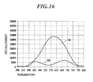
- spectral intensities of the incident white light and reflected light are depicted with solid lines 106 and 108, respectively in FIG. 16 .
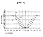
- reflectance spectrum 110 depicted with a solid line is obtained as shown in FIG. 17 .
- ligands 120 are provided on the optical film 104 in order to detect intermolecular interactions.
- the ligands 120 provided on the optical film 104 modify the optical thickness 112, leading to a change in light path length, and thus a change in interference wave length. This causes the peak shift of spectral intensity distribution of the reflected light. As a result, the reflection spectrum shifts from a solid line 110 to a dotted line 122 in FIG. 17 .
- a sample solution is then poured over the detector 100, so that binding occurs between ligands 120 on the detector 100 and analytes 130 in the sample solution as depicted in FIG. 15C .
- the binding of the ligands 120 and the analytes 130 further modifies the optical thickness 112, and the reflection spectrum 122 shifts to the reflection spectrum 132 (a dashed line) in FIG. 17 .
- the detection of a variation in bottom wavelength between the reflection spectra 122 and 132 enables intermolecular interactions to be determined.
- FIG. 18 illustrates a temporal transition of the variation in the bottom wavelengths.
- the variation in the bottom wavelength by the ligand 120 can be observed at a time point 140, while the variation in the bottom wavelength by the bonds or links between the ligand 120 and the analyte 130 can be observed at a time point 142.
- Patent Document 1 Japanese Patent No. 3786073 Non Patent DOCUMENTS
- Non Patent Document 1 Sandstrom et al, APPL.OPT., 24, 472, 1985
- a conventional device for measuring intermolecular interactions utilizing the RIfS described above includes a spectrometer for detecting reflected light which has an optical path so as to receive the white light reflected from a substrate of a detector from a light source, and thus is not provided with an optical path for receiving direct white light from a light source. Accordingly, the spectral intensity (wavelength distribution) of the initial white light, required as a reference of the estimation of a reflection spectrum from the substrate, is measured in advance during an adjustment step of the device assembly and is stored as data (hereinafter referred to as reference data). At the actual detection of a specimen, the reference data is read out and used for the estimation of the reflection spectrum.
- Such a prepared reference data of wavelength distribution characteristics does not allow for the temperature dependence of a light source at the detection of a specimen or a spectrum change in the wavelength distribution of the light source intensity due to over-time deterioration. Consequently, a reflection spectrum estimated through this reference data has a disadvantage, i.e., poor accuracy due to the temperature characteristics and the aging deterioration of the light source.
- An object of the present invention is to provide an improvement in detection accuracy of intermolecular interactions.
- the detection device can include a calculation unit to estimate a reflection spectrum through calculation of a reflectance for every predetermined wavelength range on a basis of the spectral intensities of the white light and the reflected light obtained by the control of the controller.
- the switching unit of the detection device can be configured to be a shutter mechanism selectively switchable between an optically shielded state of a light transmission via the first optical transmission path and an optically shielded state of a light transmission via the second or third optical transmission path with a shielding member, the position of the shielding member being movable.
- the switching unit of the detection device can be configured to be a liquid crystal filter selectively switchable between an optically shielded state of a light transmission via the first optical transmission path and an optically shielded state of a light transmission via the second or third optical transmission path.
- a detection method for detecting an intermolecular interaction using a detection device including a detector having a ligand, a white light source emitting white light, a spectrometer detecting spectral intensity of received light, a light transmission unit including a first optical transmission path for transmitting the white light from the white light source to the detector, a second optical transmission path for transmitting reflected light of the white light from the detector to the spectrometer and a third optical transmission path for transmitting the white light from the white light source to the spectrometer, the method including a first detection step of receiving the reflected light of the white light from the detector via the first and the second optical transmission paths and detecting the spectral intensity of the reflected light by the spectrometer, a second detection step of receiving the white light from the white light source via the third optical transmission path either before or after the first detection step and detecting the spectral intensity of the white light by the spectrometer and a calculation step of estimating a reflection spectrum by
- white light can be transmitted from a white light source to a spectrometer via a third optical transmission path of a light transmission unit, thus the reference spectral intensity of the white light can be detected at the same time together with detection of the spectral intensity of the reflection light from a detector.
- This allows the spectral intensities of both the white light and reflected light to be detected under substantially identical conditions in terms of a change in temperature and aging deterioration of the white light source, resulting in improved measurement accuracy.
- a switching unit of the detection device includes a shutter mechanism provided with an optical shielding member
- the shielding member retracts from the optical transmission path in a nonshielding state.
- the switching unit does not hinder the light transmission and suitable light transmission can be achieved.
- any shape of optical shielding region can be formed even though two optical transmission paths has a complicated cross-sectional structure.
- suitable switching of the optical transmission paths can be achieved.
- these two optical transmission paths can be switched even when the two optical transmission paths to be switched are not separated.
- FIG. 1 is a schematic view of a configuration of a detection device 1 for intermolecular interaction according to an embodiment of the present invention.
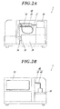
- FIGs. 2A and 2B are a right side view and a left side view, respectively, of the detection device 1 provided with an upper frame and a cover that are removed in order for the internal structure to be seen.
- FIG. 3 is a functional block diagram of the detection device 1. As shown in FIGs. 1 to 3 , the detection device 1 mainly includes a detector 10, a white light source 20, a spectrometer 30, a light transmission unit 40, a switching unit 80, a temperature control unit 90, and a controller 50.
- the detector 10 basically includes a sensor chip 12 and a flow cell 14.
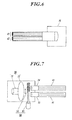
- FIG. 4 shows that the sensor chip 12 includes a rectangular silicon substrate 12a.
- a SiN (silicon nitride) film 12b is deposited on the silicon substrate 12a.
- the SiN film 12b is an exemplary optical thin film.
- the flow cell 14 is a transparent member made of silicone rubber.
- the flow cell 14 has a channel 14a therein. Close contact of the flow cell 14 to the sensor chip 12 defines a closed flow channel 14b (see FIG. 1 ). Both ends of the channel 14a protrude from the surface of the flow cell 14.
- One end is connected to a solution feeding unit 17 and serves as an inlet 14c for the supply of a sample solution.
- the other end is connected to a solution waste unit 18 and serves as an outlet 14d of the sample solution.
- Ligands 16 are bound onto the bottom of the channel 14a of the flow cell 14 (see FIG. 1 ).
- the flow cell 14 is replaceable to the sensor chip 12. This means that the flow cell 14 can be disposable.
- the surface of the sensor chip 12 can be modified, for example, with a silane coupling agent in order to assist easy replacement of the flow cell 14.
- the first optical fiber 41 is an optical guide to introduce white light emitted from the white light source 20 to the flow cell 14.
- the second optical fiber 42 is an optical guide to introduce the light from the flow cell 14 to the spectrometer 30. This enables the reflected light to be guided to the spectrometer 30 and to be detected when the closed flow channel 14b is illuminated with the white light from the white light source 20.
- the temperature control unit 90 includes a temperature control element such as a Peltier element for heating and cooling, and a temperature sensing element. These elements are installed within the detector 10.
- the controller 50 detects the temperature of the detector 10 by the temperature sensing element through a micro-computer 52 to be described later, and controls the temperature at a predetermined temperature by heating or cooling with the temperature control element.
- the light transmission unit 40 includes the first optical fiber 41 as a first optical transmission path to introduce white light from the white light source 20 to the closed flow channel 14b of the flow cell 14, the second optical fiber 42 as a second optical transmission path to introduce the reflected light of the white light from the first optical fiber 41 from the closed flow channel 14b of the flow cell 1 to the spectrometer 30, and the third optical fiber 43 as a third optical transmission path to introduce white light directly to the spectrometer 30 from the white light source 20.
- the term "to introduce the white light directly to the spectrometer 30” refers to direct introduction of the white light from the white light source 20 to the spectrometer 30 without any reflection in the midway (other than internal reflection inside the optical fiber).
- Each of the optical fibers 41 to 43 described above has a bundled structure of fine fibers.
- the first optical fiber 41 and the second optical fiber 42 have a common edge on the side of the flow cell 14 at which their fine fibers are compounded into a single bundle as depicted in FIG. 5 .
- the fine fibers 41a of the first optical fiber 41 are distributed in the center at the end face on the side of the flow cell 14, and the fine fibers 42a of the second optical fiber 42 are distributed on the periphery as to surround the bundle of the fine fibers of the first optical fiber 41.
- the fine fibers of the first optical fiber 41 are shaded in FIG. 5 for distinguishing of the fine fibers 41a from the fine fibers 42a, both fine fibers 41a and 42a are actually clear and colorless.
- the ends, on the side of the spectrometer 30, of the second optical fiber 42 and the third optical fiber 43 are connected to a connection port for receiving light for the spectrometer 30. Since the spectrometer 30 is equipped with only one connection port, the second optical fiber 42 and the third optical fiber 43 are combined into a single unit at their ends, and the unit is connected to the spectrometer 30.
- the spectrometer 30 detects the intensity of the light received by a light receiving unit for every predetermined wavelength range, and outputs the spectral intensity to the controller 50.
- the white light source 20 includes a halogen lamp 21 and a housing 22 to accommodate it.
- the housing 22 is provided with connection ports 23, 24 for connecting the first optical fiber 41 and the third optical fiber 43, respectively, as described above.
- Each of the optical fibers 41 and 43 connected to the connection ports 23 and 24, respectively, has a light incident end face arranged to face the halogen lamp 21, and a switching unit 80 is provided between the halogen lamp 21 and each of the optical fibers 41 and 43.
- the switching unit 80 mainly includes a shutter plate 81 functioning as an optical shielding member which can switch between a position to shield the light incident end face of the first optical fiber 41 and a position to shield the light incident end face of the second optical fiber 42, and a stepping motor 42 as a driving source of the shutter plate.
- the shutter plate 81 is a flat plate made of a highly light-shielding material, and is sustained by a guide mechanism (not shown) so as to be movable between the two positions mentioned above.
- the shutter plate 81 is provided with a seal to form no gap at the shielded incident end faces of the optical fibers 41 and 43 in order to ensure a high shielding effect.
- a conversion mechanism (not shown) from the rotary motion of the stepping motor 42 to a linear motion is also provided between the stepping motor 42 and the shutter plate 81.
- the driving source for the switching unit 80 is not limited to the stepping motor 42 and may be any other controllable motor or an actuator such as a linear operating air-cylinder or a solenoid.
- the switching unit 80 is controlled through a micro-computer 52 based on the control instructions by the controller 50.
- the incident end face of the third optical fiber 43 is set in the shielded state by the switching unit 80, the closed flow channel 14b of the flow cell 14 is illuminated with white light from the first optical fiber 41, and the reflected light can be transmitted to the spectrometer 30 via the second optical fiber 42 to detect the spectral intensity.
- the switching unit 80 sets the incident end face of the first optical fiber 41 in the shielded state, white light can be transmitted to the spectrometer 30 via the first optical fiber 41, and its spectral intensity can be detected.
- the controller 50 includes a PC (Personal Computer), for example, and outputs an execution command for a detection operation control to the detection device 10 upon receiving an input to execute the detection operation from an operator.
- the controller 50 thus functions as a control unit.
- the controller 50 also receives the detected data on the spectral intensity of the reference white light from the spectrometer 30 and the observed spectral intensity of the reflected light, and estimates a reflection spectrum through the calculation of reflectance for every predetermined wavelength band.
- the controller 50 thus functions as a calculation unit.
- a data communication unit 51 depicted in FIG. 3 connects the controller 50, the spectrometer 30, and the micro-computer 52, and transmits a control command from the controller 50 to the spectrometer 30 and the micro-computer 52.
- the data communication unit 51 also sends the spectral intensity data detected by the spectrometer 30 to the controller 50.
- the micro-computer 52 executes switching on/off of the white light source 20 in response to a control command from the controller 50, executes the temperature control in the temperature control unit 90 in response to a temperature setting command from the controller 50, and executes the position switching control of the shutter plate 81 in the switching unit 80 in response to a control command from the controller 50.
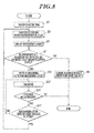
- FIG. 8 is an operational flow chart of the detection device 1 for detecting a molecular interaction.
- the detector 10 is warmed up before the detection starts (Step S1). More specifically, the controller 50 sends the micro-computer 52 a command to hold the temperature at a predetermined temperature, and the micro-computer 52 executes a temperature control of the temperature control unit 90.
- the controller 50 controls the stepping motor 82 of the switching unit 80 through the micro-computer 52 and executes the positional switching control of the shutter plate 81 to shield the incident end face of the first optical fiber 41.
- This step makes white light of the white light source 20 be introduced to the spectrometer 30 directly, thus ensuring the obtaining path for the reference light through the third optical fiber 43 (Step S3).
- the controller 50 then turns on the halogen lamp 21 of the white light source 20 through the micro-computer 52.
- the spectrometer 30 receives the white light (the reference light) via the third optical fiber 43 to detect the spectrum intensity (Step S5: first detection step).
- the controller 50 receives the spectral intensity of the reference light and determines whether or not the maximum optical intensity at a predetermined wavelength band is equal to or more than a predetermined level (Step S7). This is a process to determine whether the optical intensity reduced due to deterioration of the halogen lamp 21. For example, it determines whether the optical intensity reduced to about 90 % of that at the beginning of the use. If the optical intensity is below the predetermined level, the detection process is aborted as an error in luminescence amount of the light source and the process is terminated (Step S9).
- a sample solution 60 including an analyte 62 is supplied from the solution feeding unit 17 to the closed channel 14b of the flow cell 14, and flows through the inlet 14c, the closed channel 14b, and the outlet 14d (see FIG. 1 ).
- An analyte 62 is a material which is specifically bound to a ligand 16, and is a target molecule to be detected. Examples of a usable analyte 62 include biomolecules such as proteins, nucleic acids, lipids, and sugars, and foreign substances that are bound to biomolecules, such as drug substances and endocrine-disrupting chemicals.
- the controller 50 controls the stepping motor 82 of the switching unit 80 through the micro-computer 52 and controls the positional switching of the shutter plate 81 to shield the incident end face of the third optical fiber 43.
- white light from the white light source 20 is guided through the first optical fiber 41, and enters to illuminate the closed channel 14b of the flow cell 14.
- the reflected light at the closed channel 14b is then transmitted to the spectrometer 30 via the second optical fiber 42.
- An obtaining path to transmit the measuring light is thus ensured through the first and the second optical fibers 41 and 42 (Step S11).
- the reflected light (the measuring light) is then received by the spectrometer 30 via the second optical fiber 42, and the spectral intensity is detected (Step S13: second detection step). Then, this spectral intensity is sent to the controller 50.
- Step S15 the controller 50 determines the continuation of the measurement. If the measurement is not to be continued, the process terminates. Such a determination may be performed by setting a measuring time to judge whether the measuring time has elapsed, or by setting the measurement to be continued until receiving input of measurement termination to judge the existence or absence of the input of measurement termination.
- the reconfirmation time of the light source After which the spectral intensity of the white light (the reference light) possibly suffers from a change due to the temperature characteristics or the aging deterioration of the light source, has elapsed since the measurement of the spectral intensity of the reference light (Step S17).
- the reconfirmation time of the light source is preset in the controller 50.
- the process returns to the step S13, and the spectral intensity of the reflected light (the measuring light) is measured again. If the reconfirmation time of the light source has elapsed already, the process returns to the step S3, and the first optical fiber 41 is switched into the shielded state by the switching unit 80, then the spectral intensity of the white light (the reference light) is detected again.
- the controller 50 can acquire the spectral intensity data of the reference light and the spectral intensity data of the measuring light by executing the process control shown in the flow chart of FIG. 8 .
- the controller 50 calculates the reflectance for every predetermined wavelength band by dividing the observed optical intensity of the measuring light by the measured intensity of the reference light for the same wavelength band and estimates a reflection spectrum, with the spectral intensity of the white light (the reference light) and the spectral intensity of the reflected light (the measuring light).
- an analyte 62 in the sample solution 60 is bound to a ligand 16 as depicted in FIG. 9 .
- This binding leads to a change in the optical thickness 70, resulting in a modification of the interference color that corresponds to the wavelength of the minimum detected intensity by the spectrometer 30.
- the controller 50 calculates and identifies the bottom wavelength ⁇ bottom of the reflectance spectrums before and after the binding of the analyte 62 to the ligand 16 from the detection results obtained by the spectrometer 30.
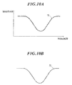
- the waveform of the reflection spectrum 72 calculated from the spectral intensity data of the reference light and the spectral intensity data of the measuring light obtained by the measurement has an irregular shape with repeated minute asperities which inhibits the calculation and the identification of the bottom wavelength ⁇ bottom (see FIG. 10A ). Accordingly, the wave form of the reflection spectrum 72 is smoothed by approximating the reflection spectrum 72 with a higher order function of approximately 20th order as depicted in FIG. 10B . Such an approximation may use any known method and is achieved, for example, by the sum of a linear function and a pseudo-Voigt function. The solution (a minimum value) is obtained from such a higher-degree polynomial, and identified as a bottom value.
- the controller 50 acquires the spectral intensity data of the reference light and the spectral intensity data of the measuring light periodically through repeated measurements. These measurements result in periodical calculation of the reflection spectrum and estimation of the bottom wavelength ⁇ bottom of the reflection spectrum to record its variation over time.
- the detection device 1 for a molecular interaction can transmit white light from the white light source 20 to the spectrometer 30 via the third optical fiber 43 of the light transmission unit 40, and thus can detect the reference spectral intensity of the white light at the same time together with the detection of the spectral intensity of the reflection light from the detector 10.
- the spectral intensities of both the white light (the reference light) and the reflected light (the measuring light) are detected under substantially identical conditions regardless of the temperature fluctuation and aging deterioration of the white light source 20, and the reflection spectrum can be estimated by the controller 50. Accordingly higher measurement accuracy can be available.
- the switching unit 80 includes a shutter mechanism and the shutter plate 81 retracts from the incident end face when each of the optical fibers 41 and 43 is not shielded; hence, no attenuating object intervenes in the incident light, ensuring a suitable light transmission.
- the location of the switching unit 80 is not limited to the white light source 20.
- the switching unit can be positioned anywhere if the switching is achieved between a reflected light receiving state and a white light receiving state, the reflected light receiving state being a state where white light is reflected in the detector 10 and can be transmitted to the spectrometer 30 via the first and the second optical fibers 41 and 42 and the white light receiving state being a state where white light can be transmitted from the white light source 20 to the detector 10 via the third optical fiber 43. Consequently the switching unit 80 may be installed either midway along both the first optical fiber 41 and the third optical fiber 43, midway along both the second optical fiber 42 and the third optical fiber 43, or between the second and the third optical fibers 42 and 43 and the spectrometer 30.
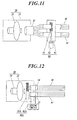
- FIG 11 illustrates an exemplary arrangement of the switching unit 80 installed midway along both the first optical fiber 41 and the third optical fiber 43.
- the shutter plate 81 is disposed in the sectioned first optical fiber 41 and third optical fiber 43.
- the gaps between the shutter plate 81 and end faces of the respective optical fibers 41 and 43 are sealed in order to avoid light penetration through the gaps.
- the housing 22 of the white light source 20 is equipped with only one connection port 23 in the case that the switching unit 80 is arranged as described above, the first optical fiber 41 and the third optical fiber 43 can be connected to the connection port 23 in a mutually integrated state by combining both ends together.
- the switching unit 80 is provided in the middle of an optical fiber in this way, it is preferable to provide a housing 83 in order to prevent penetration of the external light through the gaps at the end faces of respective fibers.
- the switching unit 80A which employs a liquid crystal filter 81A is also usable as depicted in FIG. 12 .
- the switching unit 80A is arranged inside the housing 22 of the white light source 20, and includes the liquid crystal filter 81A in close contact with the incident end faces of the two optical fibers 41 and 43, and its driving circuit 82A.
- the liquid crystal filter has two shielding areas which cover the incident end face of the first optical fiber 41 and the incident end face of the third optical fiber 43, respectively and which can be switched between a light transmittable state and a shielded state in response to an operational signal from the driving circuit 82A.
- the driving circuit 82A drives switching of the liquid crystal filter 81A under the control of the micro-computer 52.
- the liquid crystal filter 81A does not require physical movement of any component, the operation generates little physical gap and high shielding can be achieved. This allows two optical fibers 41 and 43 to be placed closer to each other and the switching unit 80A to be minimized.
- the switching unit 80A can also be manufactured into any shape to fit an area to be shielded. Even if fine fibers of the optical fibers 41 and 42 are combined into a bundle as in the example shown in FIG. 5 , the shielding area can be formed into a shape corresponding to the distribution of respective fine fibers of the optical fibers 41 and 42.
- the switching unit 80A using the liquid crystal filter 81A may also be placed either midway along both the first optical fiber 41 and the third optical fiber 43, midway along both the second optical fiber 42 and the third optical fiber 43, or in the position between the second and third optical fibers 42 and 43 and the spectrometer 30.
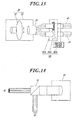
- FIG. 13 illustrates an exemplary arrangement of the switching unit 80A installed midway along both the first optical fiber 41 and the third optical fiber 43.
- the liquid crystal filter 81A is disposed between split parts of the first optical fiber 41 and between split parts of the third optical fiber 43 as well.
- the gaps between the liquid crystal filter 81A and each end face of the respective optical fibers 41 and 43 are sealed in order to avoid light penetration through the gaps. Even in this case, it is also preferable to provide a housing 83A in order to prevent penetration of the external light from the gaps at the end faces of respective optical fibers.
- the second optical fiber 42 and the third optical fiber 43 are combined into a single unit which is connected to the spectrometer 30; however, any other connection can also be employed without restriction.
- a prism 31 which has an internal reflection plane can be used as depicted in FIG. 14 .
- two optical fibers 42, 43 are connected in such a manner that the light from one optical fiber 43 (or 42) travels straight through the prism to the spectrometer 30, while the light from the other optical fiber 42 (or 43) is reflected at the reflection plane and introduced to the spectrometer 30.
- FIG. 14 the case of the example in FIG.
- the spectrometer 30 receives the light from the second optical fiber 42 and the light from the third optical fiber 43 at different areas on a light receiving plane, while in the case of prism utilization, both optical fibers 42 and 43 can introduce light to the same area of the light receiving plane of the spectrometer 30, thus allowing detection condition to be equalized.
Landscapes
- Physics & Mathematics (AREA)
- Chemical & Material Sciences (AREA)
- General Health & Medical Sciences (AREA)
- Health & Medical Sciences (AREA)
- Life Sciences & Earth Sciences (AREA)
- Analytical Chemistry (AREA)
- Biochemistry (AREA)
- General Physics & Mathematics (AREA)
- Immunology (AREA)
- Pathology (AREA)
- Chemical Kinetics & Catalysis (AREA)
- Plasma & Fusion (AREA)
- Engineering & Computer Science (AREA)
- Investigating Or Analysing Materials By Optical Means (AREA)
- Optical Measuring Cells (AREA)
Applications Claiming Priority (2)
| Application Number | Priority Date | Filing Date | Title |
|---|---|---|---|
| JP2010167835 | 2010-07-27 | ||
| PCT/JP2011/061369 WO2012014551A1 (fr) | 2010-07-27 | 2011-05-18 | Dispositif de détection et procédé de détection pour interaction intermoléculaire |
Publications (2)
| Publication Number | Publication Date |
|---|---|
| EP2600138A1 true EP2600138A1 (fr) | 2013-06-05 |
| EP2600138A4 EP2600138A4 (fr) | 2015-07-08 |
Family
ID=45529774
Family Applications (1)
| Application Number | Title | Priority Date | Filing Date |
|---|---|---|---|
| EP11812146.6A Withdrawn EP2600138A4 (fr) | 2010-07-27 | 2011-05-18 | Dispositif de détection et procédé de détection pour interaction intermoléculaire |
Country Status (5)
| Country | Link |
|---|---|
| US (1) | US8681338B2 (fr) |
| EP (1) | EP2600138A4 (fr) |
| JP (1) | JPWO2012014551A1 (fr) |
| CN (1) | CN103026203A (fr) |
| WO (1) | WO2012014551A1 (fr) |
Families Citing this family (9)
| Publication number | Priority date | Publication date | Assignee | Title |
|---|---|---|---|---|
| US10451548B2 (en) * | 2016-01-15 | 2019-10-22 | The Mitre Corporation | Active hyperspectral imaging system |
| CN105891466A (zh) * | 2016-04-26 | 2016-08-24 | 中国科学技术大学 | 一种检测生物分子的装置及方法 |
| DE102017200356A1 (de) * | 2017-01-11 | 2018-07-12 | Robert Bosch Gmbh | Verfahren zur Analyse eines Messbereichs und Miniaturspektrometer |
| CN108344714B (zh) * | 2018-01-16 | 2020-07-31 | 东南大学 | 基于有序多孔纳米结构薄膜干涉效应的生物检测仪及其进行生物分子检测的方法 |
| US10983044B2 (en) * | 2018-06-26 | 2021-04-20 | Arometrix, Inc. | Device, system and method for in-situ optical monitoring and control of extraction and purification of plant materials |
| CN113272632B (zh) * | 2018-12-27 | 2024-07-05 | ams传感器德国有限公司 | 传感器系统中温度效应的补偿 |
| US20240321400A1 (en) * | 2020-12-30 | 2024-09-26 | Seegene, Inc. | Optical spectrometry-based method and device for detecting target analyte in sample |
| CN114047140B (zh) * | 2021-12-01 | 2025-03-18 | 山东省科学院生物研究所 | 一种基于光纤复合液晶检测生化物质的装置及方法 |
| CN116735644A (zh) * | 2023-06-16 | 2023-09-12 | 苏州百源基因技术有限公司 | 基于分子互作仪的分子交互共振系统 |
Family Cites Families (14)
| Publication number | Priority date | Publication date | Assignee | Title |
|---|---|---|---|---|
| JPS63200026A (ja) | 1987-02-16 | 1988-08-18 | Sumitomo Electric Ind Ltd | 赤外分光分析器 |
| US5804453A (en) * | 1996-02-09 | 1998-09-08 | Duan-Jun Chen | Fiber optic direct-sensing bioprobe using a phase-tracking approach |
| JPH11160317A (ja) * | 1997-11-27 | 1999-06-18 | Suzuki Motor Corp | 免疫反応測定装置 |
| EP0898162A1 (fr) * | 1997-08-20 | 1999-02-24 | Suzuki Motor Corporation | Appareil d'immuno-analyse |
| JP3451536B2 (ja) | 1997-09-02 | 2003-09-29 | オムロン株式会社 | 土壌の光学特性測定装置 |
| US6512577B1 (en) * | 2000-03-13 | 2003-01-28 | Richard M. Ozanich | Apparatus and method for measuring and correlating characteristics of fruit with visible/near infra-red spectrum |
| US7507579B2 (en) * | 2002-05-01 | 2009-03-24 | Massachusetts Institute Of Technology | Apparatus and methods for simultaneous operation of miniaturized reactors |
| ES2326735T3 (es) * | 2002-05-28 | 2009-10-19 | Foss Analytical A/S | Procedimiento y espectrometro para la determinacion cuantitativa de un constituyente dentro de una muestra. |
| JP3786073B2 (ja) * | 2002-10-10 | 2006-06-14 | 株式会社日立製作所 | 生化学センサ用キットおよび測定装置 |
| US7319525B2 (en) * | 2003-11-06 | 2008-01-15 | Fortebio, Inc. | Fiber-optic assay apparatus based on phase-shift interferometry |
| JP2005321349A (ja) | 2004-05-11 | 2005-11-17 | Ishikawajima Harima Heavy Ind Co Ltd | 材質判断装置 |
| US20070165217A1 (en) * | 2005-07-08 | 2007-07-19 | Anders Johansson | Sensor structure and methods of manufacture and uses thereof |
| WO2007033318A2 (fr) | 2005-09-13 | 2007-03-22 | Edwards Lifesciences Corporation | Mesure spectroscopique continue de l'hemoglobine totale |
| US20080108122A1 (en) * | 2006-09-01 | 2008-05-08 | State of Oregon acting by and through the State Board of Higher Education on behalf of Oregon | Microchemical nanofactories |
-
2011
- 2011-05-18 CN CN201180036406XA patent/CN103026203A/zh active Pending
- 2011-05-18 EP EP11812146.6A patent/EP2600138A4/fr not_active Withdrawn
- 2011-05-18 US US13/812,353 patent/US8681338B2/en not_active Expired - Fee Related
- 2011-05-18 JP JP2012526356A patent/JPWO2012014551A1/ja active Pending
- 2011-05-18 WO PCT/JP2011/061369 patent/WO2012014551A1/fr not_active Ceased
Also Published As
| Publication number | Publication date |
|---|---|
| JPWO2012014551A1 (ja) | 2013-09-12 |
| EP2600138A4 (fr) | 2015-07-08 |
| US20130122607A1 (en) | 2013-05-16 |
| WO2012014551A1 (fr) | 2012-02-02 |
| US8681338B2 (en) | 2014-03-25 |
| CN103026203A (zh) | 2013-04-03 |
Similar Documents
| Publication | Publication Date | Title |
|---|---|---|
| US8681338B2 (en) | Detection device and detection method for intermolecular interaction | |
| CA2867125C (fr) | Dispositif d'analyse interactif et appareil a mecanisme de synchronisation | |
| EP2546632B1 (fr) | Procédé et dispositif de détection d'interactions moléculaires utilisant la spectroscopie interférentielle à réflexion | |
| US12313527B2 (en) | Digital microfluidic systems, cartridges, and methods including integrated refractive index sensing | |
| JP6337905B2 (ja) | 表面プラズモン共鳴蛍光分析方法および表面プラズモン共鳴蛍光分析装置 | |
| JPWO2005054826A1 (ja) | 光分析装置及び光分析デバイス | |
| EP3153845B1 (fr) | Procédé de mesure par fluorescence activée par plasmons de surface et dispositif de mesure par fluorescence activée par plasmons de surface | |
| US9008373B2 (en) | Device, system and method for transit testing of samples | |
| JP6477488B2 (ja) | 検出装置および当該検出装置を用いた検出方法 | |
| US20130267034A1 (en) | Intermolecular interaction measurement method, measurement system for use in the method, and program | |
| JP7206570B2 (ja) | 分析装置 | |
| CN101583873B (zh) | 免疫色谱试验片的测定方法 | |
| JP6648764B2 (ja) | 反応方法 | |
| EP3505913A1 (fr) | Procédé de mesure, appareil de mesure et système de mesure | |
| JP6760384B2 (ja) | 測定方法 | |
| JP2008089579A (ja) | 生化学測定装置 | |
| EP1064095A1 (fr) | Procede et appareil de mesure de proteines | |
| EP3217164A1 (fr) | Dispositif de détection et procédé de détection | |
| KR20250162362A (ko) | 광학계가 개선된 진단 장치 | |
| US20100215545A1 (en) | Biochemical measuring device | |
| JP2018009802A (ja) | 検出方法および検出装置 |
Legal Events
| Date | Code | Title | Description |
|---|---|---|---|
| PUAI | Public reference made under article 153(3) epc to a published international application that has entered the european phase |
Free format text: ORIGINAL CODE: 0009012 |
|
| 17P | Request for examination filed |
Effective date: 20130123 |
|
| AK | Designated contracting states |
Kind code of ref document: A1 Designated state(s): AL AT BE BG CH CY CZ DE DK EE ES FI FR GB GR HR HU IE IS IT LI LT LU LV MC MK MT NL NO PL PT RO RS SE SI SK SM TR |
|
| DAX | Request for extension of the european patent (deleted) | ||
| RA4 | Supplementary search report drawn up and despatched (corrected) |
Effective date: 20150610 |
|
| RIC1 | Information provided on ipc code assigned before grant |
Ipc: G01N 21/55 20140101ALI20150603BHEP Ipc: G01N 21/552 20140101ALI20150603BHEP Ipc: G01N 21/77 20060101ALI20150603BHEP Ipc: G01N 33/543 20060101ALI20150603BHEP Ipc: G01N 21/27 20060101AFI20150603BHEP |
|
| 18D | Application deemed to be withdrawn |
Effective date: 20160106 |
|
| STAA | Information on the status of an ep patent application or granted ep patent |
Free format text: STATUS: THE APPLICATION IS DEEMED TO BE WITHDRAWN |
|
| R18D | Application deemed to be withdrawn (corrected) |
Effective date: 20160108 |