EP2600446B1 - Matériau actif négatif - Google Patents
Matériau actif négatif Download PDFInfo
- Publication number
- EP2600446B1 EP2600446B1 EP10855377.7A EP10855377A EP2600446B1 EP 2600446 B1 EP2600446 B1 EP 2600446B1 EP 10855377 A EP10855377 A EP 10855377A EP 2600446 B1 EP2600446 B1 EP 2600446B1
- Authority
- EP
- European Patent Office
- Prior art keywords
- active material
- atom
- phase
- negative electrode
- silicon
- Prior art date
- Legal status (The legal status is an assumption and is not a legal conclusion. Google has not performed a legal analysis and makes no representation as to the accuracy of the status listed.)
- Active
Links
Images


Classifications
-
- H—ELECTRICITY
- H01—ELECTRIC ELEMENTS
- H01M—PROCESSES OR MEANS, e.g. BATTERIES, FOR THE DIRECT CONVERSION OF CHEMICAL ENERGY INTO ELECTRICAL ENERGY
- H01M4/00—Electrodes
- H01M4/02—Electrodes composed of, or comprising, active material
- H01M4/36—Selection of substances as active materials, active masses, active liquids
- H01M4/38—Selection of substances as active materials, active masses, active liquids of elements or alloys
- H01M4/386—Silicon or alloys based on silicon
-
- H—ELECTRICITY
- H01—ELECTRIC ELEMENTS
- H01M—PROCESSES OR MEANS, e.g. BATTERIES, FOR THE DIRECT CONVERSION OF CHEMICAL ENERGY INTO ELECTRICAL ENERGY
- H01M10/00—Secondary cells; Manufacture thereof
- H01M10/05—Accumulators with non-aqueous electrolyte
- H01M10/052—Li-accumulators
- H01M10/0525—Rocking-chair batteries, i.e. batteries with lithium insertion or intercalation in both electrodes; Lithium-ion batteries
-
- H—ELECTRICITY
- H01—ELECTRIC ELEMENTS
- H01M—PROCESSES OR MEANS, e.g. BATTERIES, FOR THE DIRECT CONVERSION OF CHEMICAL ENERGY INTO ELECTRICAL ENERGY
- H01M4/00—Electrodes
- H01M4/02—Electrodes composed of, or comprising, active material
- H01M4/13—Electrodes for accumulators with non-aqueous electrolyte, e.g. for lithium-accumulators; Processes of manufacture thereof
- H01M4/134—Electrodes based on metals, Si or alloys
-
- H—ELECTRICITY
- H01—ELECTRIC ELEMENTS
- H01M—PROCESSES OR MEANS, e.g. BATTERIES, FOR THE DIRECT CONVERSION OF CHEMICAL ENERGY INTO ELECTRICAL ENERGY
- H01M4/00—Electrodes
- H01M4/02—Electrodes composed of, or comprising, active material
- H01M4/36—Selection of substances as active materials, active masses, active liquids
- H01M4/362—Composites
- H01M4/364—Composites as mixtures
-
- H—ELECTRICITY
- H01—ELECTRIC ELEMENTS
- H01M—PROCESSES OR MEANS, e.g. BATTERIES, FOR THE DIRECT CONVERSION OF CHEMICAL ENERGY INTO ELECTRICAL ENERGY
- H01M4/00—Electrodes
- H01M4/02—Electrodes composed of, or comprising, active material
- H01M4/36—Selection of substances as active materials, active masses, active liquids
- H01M4/38—Selection of substances as active materials, active masses, active liquids of elements or alloys
-
- H—ELECTRICITY
- H01—ELECTRIC ELEMENTS
- H01M—PROCESSES OR MEANS, e.g. BATTERIES, FOR THE DIRECT CONVERSION OF CHEMICAL ENERGY INTO ELECTRICAL ENERGY
- H01M4/00—Electrodes
- H01M4/02—Electrodes composed of, or comprising, active material
- H01M4/36—Selection of substances as active materials, active masses, active liquids
- H01M4/48—Selection of substances as active materials, active masses, active liquids of inorganic oxides or hydroxides
- H01M4/52—Selection of substances as active materials, active masses, active liquids of inorganic oxides or hydroxides of nickel, cobalt or iron
- H01M4/525—Selection of substances as active materials, active masses, active liquids of inorganic oxides or hydroxides of nickel, cobalt or iron of mixed oxides or hydroxides containing iron, cobalt or nickel for inserting or intercalating light metals, e.g. LiNiO2, LiCoO2 or LiCoOxFy
-
- H—ELECTRICITY
- H01—ELECTRIC ELEMENTS
- H01M—PROCESSES OR MEANS, e.g. BATTERIES, FOR THE DIRECT CONVERSION OF CHEMICAL ENERGY INTO ELECTRICAL ENERGY
- H01M4/00—Electrodes
- H01M4/02—Electrodes composed of, or comprising, active material
- H01M4/36—Selection of substances as active materials, active masses, active liquids
- H01M4/58—Selection of substances as active materials, active masses, active liquids of inorganic compounds other than oxides or hydroxides, e.g. sulfides, selenides, tellurides, halogenides or LiCoFy; of polyanionic structures, e.g. phosphates, silicates or borates
- H01M4/581—Chalcogenides or intercalation compounds thereof
-
- H—ELECTRICITY
- H01—ELECTRIC ELEMENTS
- H01M—PROCESSES OR MEANS, e.g. BATTERIES, FOR THE DIRECT CONVERSION OF CHEMICAL ENERGY INTO ELECTRICAL ENERGY
- H01M4/00—Electrodes
- H01M4/02—Electrodes composed of, or comprising, active material
- H01M2004/021—Physical characteristics, e.g. porosity, surface area
-
- Y—GENERAL TAGGING OF NEW TECHNOLOGICAL DEVELOPMENTS; GENERAL TAGGING OF CROSS-SECTIONAL TECHNOLOGIES SPANNING OVER SEVERAL SECTIONS OF THE IPC; TECHNICAL SUBJECTS COVERED BY FORMER USPC CROSS-REFERENCE ART COLLECTIONS [XRACs] AND DIGESTS
- Y02—TECHNOLOGIES OR APPLICATIONS FOR MITIGATION OR ADAPTATION AGAINST CLIMATE CHANGE
- Y02E—REDUCTION OF GREENHOUSE GAS [GHG] EMISSIONS, RELATED TO ENERGY GENERATION, TRANSMISSION OR DISTRIBUTION
- Y02E60/00—Enabling technologies; Technologies with a potential or indirect contribution to GHG emissions mitigation
- Y02E60/10—Energy storage using batteries
-
- Y—GENERAL TAGGING OF NEW TECHNOLOGICAL DEVELOPMENTS; GENERAL TAGGING OF CROSS-SECTIONAL TECHNOLOGIES SPANNING OVER SEVERAL SECTIONS OF THE IPC; TECHNICAL SUBJECTS COVERED BY FORMER USPC CROSS-REFERENCE ART COLLECTIONS [XRACs] AND DIGESTS
- Y02—TECHNOLOGIES OR APPLICATIONS FOR MITIGATION OR ADAPTATION AGAINST CLIMATE CHANGE
- Y02P—CLIMATE CHANGE MITIGATION TECHNOLOGIES IN THE PRODUCTION OR PROCESSING OF GOODS
- Y02P70/00—Climate change mitigation technologies in the production process for final industrial or consumer products
- Y02P70/50—Manufacturing or production processes characterised by the final manufactured product
Definitions
- the present invention relates to a negative electrode active material and a secondary battery.
- a secondary battery is a chemical cell that can be repeatedly charged and discharged using an electrochemical reaction.
- One representative example of the secondary battery is a lithium secondary battery.
- a lithium secondary battery for example, a carbon-based material such as graphite is used for a negative electrode, a lithium-containing compound is used for a positive electrode, and a lithium salt is used for an electrolyte.
- Portable electronic equipment is provided with a device having high power consumption, such as a central processing unit (CPU) and a liquid crystal display device (LCD), and shows increasing power consumption with multifunctionality. Therefore, a lithium secondary battery frequently used as an electric power source of the electronic equipment is required to realize a high-capacity design.
- a widely used negative electrode active material however, graphite has a problem in that it is difficult to achieve a high charge/discharge capacity.
- a cell using silicon (Si) as a negative electrode material has a problem in that an expansion in volume of the silicon (Si) may take place during a charge cycle when lithium ions transferred to the negative electrode are intercalated into the silicon (Si). Also, the lithium ions are deintercalated from the silicon (Si) during a discharge cycle, which leads to re-contraction of the silicon (Si). As a result, a metal is ground into a powder and a cycle property may be degraded as the charge/discharge test is repeatedly carried out.
- Japanese Patent Laid-open Publication No. 2006-286312 disclosed a lithium secondary battery using a silicon thin film formed through a dry process as a negative electrode active material.
- the silicon thin film has a structure which is separated in a main phase according to a short circuit formed in a thickness direction thereof.
- Japanese Patent Laid-open Publication No. 2006-286312 there have been attempts conducted to reduce the expansion and contraction of silicon (Si) using a physical shape of a silicon thin film, but the productivity of the thin film is severely lowered, which makes it difficult to apply the thin film to mass production of cells.
- KR 2010 0080479 A discloses an anode active material including: a crystalline phase comprising Si and a Si-metal alloy; and an amorphous phase comprising Si and a Si-metal alloy, wherein the metal of the Si-metal alloy of the crystalline phase is the same as or different from the metal of the Si-metal alloy of the amorphous phase.
- the object of the present invention as defined in the claims is to provide a negative electrode active material and a secondary battery.
- the present invention relates to a negative electrode active material as defined in the claims, including a phase A including an active silicon, and a phase B including a metal alloy matrix including a silicon and a transition metal.
- the negative electrode active material satisfies the requirements of the following Expression 1. X ⁇ 500 Hv
- the "X" represents the Vickers hardness of the alloy matrix, as measured at 100 gf.
- the peaks other than a peak derived from the active silicon of the phase A, the peaks being observed in an ex situ X-ray diffraction (XRD) analysis before the charge/discharge, are also identically observed after the charge/discharge.
- the negative electrode active material includes the phase A including the active silicon, preferably consisting only of the active silicon, and the phase B including the alloy matrix including the silicon and other transition metals as defined in the claims.
- the negative electrode active material may have a structure in which the active silicon of the phase A forms a core and the alloy matrix of the phase B surrounds the core of the active silicon of the phase A.
- the metal alloy matrix of the phase B may be in the form of a band, of which an average thickness is in the range from approximately 10 nm to 100 nm.
- the negative electrode active material may have a structure in which a large amount of fine active silicons are in the negative electrode active material and each of the active silicons are firmly connected by the metal alloy matrix, and the active silicon of the phase A is surrounded by the metal alloy matrix of the phase B.
- the alloy matrix shows both of the high hardness and the embrittlement property due to its innate alloy composition, and has excellent electric conductivity and the electrochemical property. According to the fine structure of the active material, expansion of the pole plate may be effectively suppressed during the charge/discharge, and a lifespan property may be ensured. Therefore, the negative electrode active material of the present invention as defined in the claims may be applied to a secondary battery so as to show excellent performance.
- the phase A includes the active silicon as a main component, and preferably includes only the active silicon. That is, the phase A may be formed of a single phase of the active silicon so as to maximize an amount of the intercalated lithium ions when the negative electrode active material is applied to a secondary battery.
- the active silicon in the phase A may have uniformly organized appearances, for example, particle shapes, and the like, but is not limited thereto. Also, in the active silicon of the phase A, each of the active silicon particles may be divided, or at least a part of the silicon may be partially connected with each other so as to form continuous phases.
- the active silicon in the phase A may have an average particle diameter of 1,000 nm or less, preferably 100 nm to 500 nm, and more preferably 10 nm to 100 nm. If the particle diameter of the active silicon of the phase A is too high, a thickness of the metal alloy matrix may be reduced, and cracks may appear in the phase A during the charge/discharge, causing an electrical short circuit. Therefore, when the average particle diameter of the active silicon is controlled within this range, the cracks may be prevented from appearing in the phase A.
- the active silicon of the phase A may be included at a ratio of approximately 30 atom% to 80 atom%, relative to the total amount of elements in the active material.
- the ratio of the active silicon of the phase A is controlled within this range, the secondary battery may have a high-capacity property and also maintain excellent cell efficiency and lifespan when the active material is applied to the secondary battery.
- the active material includes the phase B including the metal alloy matrix.
- the matrix includes silicon as a constituent element of the matrix.
- the silicon in the matrix of the phase B may be distinguished from the active silicon in the phase A. That is, the alloy matrix of the phase B is an alloy that includes three (ternary) elements, including the silicon and Fe and Ti (transition metals other than the silicon), as members of the alloy.
- the matrix included in the phase B have substantially no reactivity with lithium or ion thereof which is a component in the electrolyte of the secondary battery, for example, when it is applied to the secondary battery.
- the term "substantially no reactivity" as used herein may refer to a case where the matrix does not react with the lithium or ion thereof at all, or a case where the matrix has sufficiently low reactivity with the lithium or ion thereof, therefore the reaction doesn't affect predetermined effects even when being somewhat reacted with the lithium or ion thereof
- the matrix of the phase B which doesn't show the reactivity with the lithium and the active silicon of the phase A may effectively suppress expansion and contraction of the active silicon of the phase A, and also may improve characteristics such as cycle property, efficiency and lifespan when the active material is applied to cells.
- the peaks other than peaks derived from the active silicon in the phase A which are observed by the ex situ XRD analysis with respect to the material before the charge/discharge test, are also identically observed after the charge/discharge test.
- the term "identically observed peaks” as used herein may refer to a case where peaks other than peaks derived from the active silicon in the phase A, i.e., peaks derived from the metal alloy matrix in the phase B, which are observed in the ex situ XRD performed with respect to the active material before the charge/discharge test, are also observed at the substantially identical diffraction angle without the shifting after the charge/discharge test.
- the conditions required for the charge/discharge test and the ex situ XRD analysis are not particularly limited.
- the charge/discharge test and the ex situ XRD analysis may be performed using a method known in the related art, and, more particularly, a method described in Examples of this specification.
- the peaks derived from the active silicon of the phase A in the ex situ XRD analysis are observed at diffraction angles (20) of approximately 28.8 degrees and approximately 47.8 degrees, and therefore the peaks other than the peaks derived from the active silicon of the phase A may be, for example, peaks observed at a diffraction angle (20) of greater than approximately 28.8 degrees and less than approximately 47.8 degrees during the ex situ XRD analysis.
- the matrix included in the phase B includes silicon (Si) as a constituent element of the alloy, as described above. Therefore, the matrix shows sufficiently high hardness to effectively suppress expansion or contraction depending on which lithium ions are intercalated or deintercalated.
- the negative electrode active material according to the present invention as defined in the claims shows a high hardness represented by Expression 1 due to the distinctive matrix compositions as described above.
- the active material according to the present invention as defined in the claims has a Vickers hardness X of 500 Hv or more, preferably 600 Hv or more, more preferably 800 Hv or more, and further preferably 1,000 Hv, as measured at a load of 100 gf.
- the upper limit of the Vickers hardness X is not particularly limited, and may be, for example, the same as or less than 2,000 Hv.
- the active material according to the present invention as defined in the claims shows an excellent hardness property as represented by Expression 1, and thus may effectively suppress expansion of a pole plate and improve efficiency and lifespan of cells when the active material is applied to a lithium secondary battery.
- a method of measuring the Vickers hardness is not particularly limited.
- the Vickers hardness may be measured using a conventional Vickers hardness measuring method known in the art, and, more particularly, using a method described in Examples of this specification.
- the active material according to one exemplary embodiment of the present invention as defined in the claims shows an excellent embrittlement property in addition to the high Vickers hardness as described above. More particularly, the active material may satisfy the requirements of the following Expression 2, as well as the requirements of Expression 1. Y ⁇ 15 ⁇ m
- Y represents a D 50 value of a milled product as measured after the active material is milled for 24 hours using a ball mill machine.
- the active material according to one exemplary embodiment of the present invention as defined in the claims may have a Y (D 50 ) value of 10 ⁇ m or less.
- the lower limit of the D 50 value (Y) is not particularly limited, and may be, for example, the same as or greater than 2 ⁇ m.
- conditions required to mill the active material and a method of measuring a D 50 value may be set and performed using a method described in Examples of this specification.
- the active material according to one exemplary embodiment of the present invention as defined in the claims also shows excellent electric conductivity due to the distinctive matrix compositions. More particularly, the active material according to one exemplary embodiment of the present invention as defined in the claims may have an electric conductivity of 5 ⁇ 10 1 S/cm or more, preferably 5.5 ⁇ 10 1 S/cm or more, and more preferably 6 ⁇ 10 1 S/cm or more, as measured at a load of 20 kN.
- the upper limit of the electric conductivity of the active material according to one exemplary embodiment of the present invention as defined in the claims is not particularly limited, and may be, for example, the same as or less than 20 ⁇ 10 1 S/cm.
- the active material according to one exemplary embodiment of the present invention as defined in the claims shows the excellent electric conductivity, the efficiency and lifespan of cells may be improved when the active material is applied to a secondary battery.
- the electric conductivity described above may be measured using a conventional method known in the related art, and, more particularly, a method provided in Examples of this specification.
- the transition metal is Ti and Fe. That is, in the present invention as defined in the claims, the metal alloy matrix is a Si-Ti-Fe ternary alloy.
- the metal alloy matrix may be included at a ratio of 20 atom% to 70 atom%.
- the matrix may effectively surround the phase A in the form of a band, so that the active material shows a high-capacity property.
- phase A and the phase B are be present in the form of an alloy represented by the following Formula 1. aSi ⁇ bTi ⁇ cFe
- a, b and c are represented by the unit "atom%", and the sum of a, b and c is 100 atom%.
- a represents an atomic ratio of the sum of silicon in the active material present in the form of an alloy, particularly, active silicon of the phase A, and silicon included in the matrix of the phase B.
- the atomic ratio is in a range of 30 to 80 atom%, preferably 50 to 80 atom%.
- b in Formula 1 represents an atomic ratio of titanium (Ti) included in the matrix.
- the atomic ratio of titanium (Ti) is in a range of 35 atom% or less, and more than 0 atom%, preferably 10 to 25 atom%.
- c in Formula 1 represents an atomic ratio of iron (Fe) included in the matrix.
- the atomic ratio of iron (Fe) is in a range 35 atom% or less, and more than 0 atom%, preferably 10 to 25 atom%.
- the active material when the ratio of the constituent element in the active material is controlled as described above, the active material may be applied to a secondary battery to show excellent cycle and efficiency properties.
- both of the phase A (active silicon) and the phase B (metal alloy matrix) may be present in a crystalline form.
- both of the phase A and the phase B are present in a crystalline form, excellent initial efficiency of a secondary battery may be especially maintained.
- a method of preparing the negative electrode active material according to one exemplary embodiment of the present invention as defined in the claims is not particularly limited.
- the active material may be prepared using various alloying techniques known in the related art.
- the active material may be, for example, prepared using a quenching method, which includes mixing silicon and components constituting the metal matrix, melting the resulting mixture using an arc melting method, and dispersing the molten product in a rotating kappa roll.
- the method applicable to the present invention as defined in the claims is not limited thereto.
- any methods may be used without limitation as long as they can be used to achieve a sufficient quenching rate.
- a desired negative electrode active material may be prepared by adjusting the kinds and blending ratios of the compositions of the alloy elements used in the various methods as described above.
- Still another aspect of the present invention provides a secondary battery as defined in the claims including a positive electrode, a negative electrode including the active material according to one exemplary embodiment of the present invention, and an electrolyte.
- the kind of the positive electrode that may be used in the secondary battery of the present invention as defined in the claims is not particularly limited.
- a material that can perform an electrochemically reversible redox reaction may be used as the positive electrode.
- a lithiated intercalation compound may be used.
- Examples of the above-described compound that may be used in the present invention as defined in the claims may include at least one compound selected from the group consisting of the following Formulas 2 to 25, but the present invention as defined in the claims is not limited thereto.
- a is in a range of 0.95 to 1.1
- b is in a range of 0 to 0.5: Li a E 1 ⁇ b B b O 2 ⁇ c F c
- a is in a range of 0.95 to 1.1
- b is in a range of 0 to 0.5
- c is in a range of 0 to 0.05: Li E 2 ⁇ b B b O 4 ⁇ c R c
- b is in a range of 0 to 0.5
- c is in a range of 0 to 0.05: Li a Ni 1 ⁇ b ⁇ c Co b B c D ⁇
- a is in a range of 0.95 to 1.1
- b is in a range of 0 to 0.5
- c is in a range of 0 to 0.05
- ⁇ is greater than 0 and less than or equal to 2: Li a Ni 1 ⁇ b ⁇ c Co b B c O 2 ⁇ ⁇ F ⁇
- a is in a range of 0.95 to 1.1
- b is in a range of 0 to 0.5
- c is in a range of 0 to 0.05
- ⁇ is greater than 0 and less than 2: Li a Ni 1 ⁇ b ⁇ c Co b B c O 2 ⁇ ⁇ F 2
- a is in a range of 0.95 to 1.1
- b is in a range of 0 to 0.5
- c is in a range of 0 to 0.05
- ⁇ is greater than 0 and less than 2: Li a Ni 1 ⁇ b ⁇ c Mn b B c D ⁇
- a is in a range of 0.95 to 1.1
- b is in a range of 0 to 0.5
- c is in a range of 0 to 0.05
- ⁇ is greater than 0 and less than or equal to 2: Li a Ni 1 ⁇ b ⁇ c Mn b B c O 2 ⁇ ⁇ F ⁇
- a is in a range of 0.95 to 1.1
- b is in a range of 0 to 0.5
- c is in a range of 0 to 0.05
- ⁇ is greater than 9 and less than 2: Li a Ni 1 ⁇ b ⁇ c Mn b B c O 2 ⁇ ⁇ F 2
- a is in a range of 0.95 to 1.1
- b is in a range of 0 to 0.5
- c is in a range of 0 to 0.05
- ⁇ is greater than 0 and less than 2: Li a Ni b E c G d O 2
- a is in a range of 0.90 to 1.1
- b is in a range of 0 to 0.9
- c is in a range of 0 to 0.5
- d is in a range of 0.001 to 0.1: Li a Ni b Co c Mn d GeO 2
- a is in a range of 0.90 to 1.1
- b is in a range of 0 to 0.9
- c is in a range of 0 to 0.5
- d is in a range of 0 to 0.5
- e is in a range of 0.001 to 0.1: Li a NiG b O 2
- a is in a range of 0.90 to 1.1, and b is in a range of 0.001 to 0.1: Li a CoG b O 2
- a is in a range of 0.90 to 1.1
- b is in a range of 0.001 to 0.1: Li a MnG b O 2
- a is in a range of 0.90 to 1.1, and b is in a range of 0.001 to 0.1: Li a Mn 2 G b O 4
- a is in a range of 0.90 to 1.1, and b is in a range of 0.001 to 0.1: QO 2 QS 2 LiQS 2 V 2 O 5 LiV 2 O 5 LiIO 2 LiNiVO 4 Li 3 ⁇ f J 2 PO 4 3
- f is in a range of 0 to 3.
- f is in a range of 0 to 2.
- A may be one or a combination of two or more selected from the group consisting of Ni, Co and Mn
- B may be one or a combination of two or more selected from the group consisting of Al, Ni, Co, Mn, Cr, Fe, Mg, Sr, V and a rare-earth element
- D may be one or a combination of two or more selected from the group consisting of O
- F, S and P E may be one or a combination of two selected from the group consisting of Co and Mn
- F may be one or a combination of two or more selected from the group consisting of F, S and P
- G may be one or a combination of two or more selected from the group consisting of Al, Cr, Mn, Fe, Mg, La, Ce, Sr and V
- Q may be one or a combination of two or more selected from the group consisting of Ti, Mo and Mn
- I may be one or a combination of two or more selected from the group consisting of Cr, V, Fe, Sc and Y
- J may be
- elemental sulfur (S 8 ) and a sulfur compound may also be used in the present invention as defined in the claims.
- the kinds of electrolytes included in the secondary battery according to one exemplary embodiment of the present invention as defined in the claims are not particularly limited, and typical electrolytes known in the related art may be selected and used.
- the electrolyte may include a non-aqueous organic solvent and a lithium salt.
- the lithium salt may be dissolved in an organic solvent so that it can serve as a lithium ion source in a cell, and may promote transfer of lithium ions between the positive electrode and the negative electrode.
- lithium salt examples include one or two or more of LiPF 6 , LiBF 4 , LiSbF 6 , LiAsF 6 , LiCF 3 SO 3 , LiN(CF 3 SO 2 ) 3 , Li(CF 3 SO 2 ) 2 N, LiC 4 F 9 SO 3 , LiClO 4 , LiAlO 4 , LiAlCl 4 , LiN(C x F 2x +1SO 2 ) (C y F2 y +1SO 2 ) (wherein x and y are natural numbers), LiCl, LiI, and lithium bisoxalate borate as a supporting electrolyte salt.
- a concentration of the lithium salt in the electrolyte may vary according to applications. Typically, the lithium salt may be used at a concentration of 0.1 to 2.0 M.
- the organic solvent may also serve as a medium through which ions taking part in an electrochemical reaction of a cell can move.
- the organic solvent may include, but are not limited to, benzene, toluene, fluorobenzene, 1,2-difluorobenzene, 1,3-difluorobenzene, 1,4-difluorobenzene, 1,2,3-trifluorobenzene, 1,2,4-trifluorobenzene, chlorobenzene, 1,2-dichlorobenzene, 1,3-dichlorobenzene, 1,4-dichlorobenzene, 1,2,3-trichlorobenzene, 1,2,4-trichlorobenzene, iodobenzene, 1,2-diiodobenzene, 1,3-diiodobenzene, 1,4-diiodobenzene, 1,2,3-triiodobenzene, 1,2,4-triiodobenzene,
- the secondary battery according to one exemplary embodiment of the present invention as defined in the claims may further include a conventional element such as a separator, a can, a cell case or a gasket.
- a conventional element such as a separator, a can, a cell case or a gasket.
- specific kinds of the conventional element are not particularly limited.
- the secondary battery according to one exemplary embodiment of the present invention as defined in the claims includes the elements as described above. Therefore, the secondary battery according to one exemplary embodiment of the present invention as defined in the claims may be manufactured in a typical shape known in the related art using a typical method known in the related art. Examples of the shape of the secondary battery according to one exemplary embodiment of the present invention as defined in the claims may include a tubular shape, a horn shape, a coin shape or a pouch shape, but the present invention as defined in the claims is not limited thereto.
- the present invention as defined in the claims can provide a negative electrode active material capable of maintaining excellent cell efficiency and lifespan while showing high-capacity properties, and a secondary battery manufactured using the same.
- Si Silicon
- Ti titanium
- Fe iron
- Si:Ti:Fe 67%:16.5%:16.5%
- the prepared alloy was subjected to the melt spinning process that is the rapid solidification method, thereby preparing the negative electrode active material in which the active silicon (Si) particles (phase A) were positioned in the band shaped Si-Ti-Fe alloy matrix (phase B).
- the rapid cooling rate (the rotary rate of the kappa roll) was approximately 3,500 rpm.
- the negative electrode active material was prepared in the same manner as in Example 1, except that the mixing ratio (Si:Ti:Fe) was controlled to be 70%:15%:15%.
- the negative electrode active material was prepared in the same manner as in Example 1, except that the mixing ratio (Si:Ti:Fe) was controlled to be 74%:13%:13%.
- a negative electrode active material including the phase A of the active silicon (Si) and the phase B of Ti-Ni matrix was prepared in the same manner as in Example 1, except that silicon (Si), titanium (Ti) and nickel (Ni) were mixed at a ratio of 70%:15%:15% (Si:Ti:Ni).
- FIG. 1 is an SEM image of the negative electrode active material in Example 1 (with a magnification of 40,000 times)
- FIG. 2 is a TEM image of the active material.
- a bright region observed in FIG. 2 represents the active silicon constituting the phase A (average particle size: approximately 50 ⁇ m).
- FIG. 3 is an SEM image of the negative electrode active material in Example 2 (with a magnification of 20,000 times). As shown in FIG. 3 , it was confirmed that the active silicon having an average particle diameter of approximately 200 nm was uniformly formed in the negative electrode active material prepared in Example 2, and a band of a Si-Ti-Fe ternary alloy matrix surrounded the active silicon.
- the Cuk ⁇ -ray XRD measurements were performed with respect to the negative electrode active materials in Examples 1 to 3. The results are shown in FIG. 4 .
- the measurement angle was in the range from 10 degrees to 100 degrees, and the measuring rate was set to 4 degrees per minute.
- FIG. 4 it could be seen that the peaks ( ⁇ ) derived from the active silicon and the peaks ( ⁇ ) derived from the Si-Ti-Fe alloy were observed in the negative electrode active materials in Example 1 to 3, and thus the phase A formed of the active silicon and the phase B formed of the Si-Ti-Fe alloy were present in the active material.
- the presence of the Si-Ti-Fe alloy was confirmed even when the content of silicon was altered from 67 atom% to 74 atom% while maintaining Ti and Fe at an atomic ratio of 1:1.
- a pole plate was manufactured using the rapidly cooled ribbon in Example 2, and it was subjected to the coin cell evaluation. The results are shown in FIGS. 5 and 6 .
- the active material a conducting agent (Super P-based conducting agent) and a binder (PI-based binder) was mixed at a mixing ratio of 86.6:3.4:10 (the active material:the conducting agent:the binder) (based on the weight).
- the manufactured pole plate was repeatedly charged/discharged, once at 0.1 C, and then 10 times at 0.5 C, and then measured for voltage and current quantity. In this case, the charge/discharge test was performed according to a method of charging/discharging an active material for lithium secondary batteries as is widely known in the related art.
- FIG. 6 shows the results obtained by measuring a change in capacity according to the number of cycles after the negative electrode active material prepared in Example 2 was repeatedly charged/discharged, once at 0.1 C, and then 50 times at 0.5 C. As shown in FIG. 6 , it could be seen that the discharging capacity was uniformly maintained after the repeated charge/discharge tests.
- a coin cell was manufactured in the same manner as performed for the analyses of FIGS. 5 and 6 , using the rapidly cooled ribbon in Example 2. Thereafter, to check reactivity of the metal matrix with the active silicon and lithium, a DCP was drawn from the charging/discharging results to determine an electric potential at which a reaction took place. Then, the observed electric potential was selected to perform an ex situ XRD analysis at a corresponding electric potential (measurement angle: 20 degrees to 60 degrees). The results are shown in FIGS. 7 and 8 . In this case, the charging/discharging conditions were set as follows, and the other conditions were set based on a typical method of charging/discharging an active material for lithium secondary batteries.
- FIG. 8 shows the ex situ XRD peaks (pristine) before the charge/discharge test and the ex situ XRD peaks (Li in 0.01 V, Li out 0.5 V, and Li out 2 V) when the charge/discharge test was performed once.
- FIG. 9 shows samples after their hardness was measured, showing images taken of the sample 1 in the left panel (a) and images taken of the sample 2 in the right panel (b). As shown in FIG. 9 , it was seen that the sample 1 had a higher embrittlement property than sample 2 since cracks were observed around a pressed region after the hardness was measured.
- the embrittlement was evaluated using the active materials prepared in Example 2 and Comparative Example 1. More particularly, each of the active materials was milled with an increasing period of time using a ball mill machine (average particle size before milling: approximately 400 ⁇ m to 1 mm). At the same time, particle sizes of the active materials were measured (D 50 value). In this case, the milling conditions were set as follows, and the particle size was measured using a typical method known in the related art.
- the negative electrode active material according to one exemplary embodiment of the present invention as defined in the claims had an excellent electric conductivity of 6.175E+01 S/cm even when the active material was present at a load of 20 kN. Therefore, although cracks on the active material were caused, and thus the active material was ground into powder during a charge/discharge test, the negative electrode active material itself showed the excellent electric conductivity, thereby inhibiting an electrical short circuit from being formed between the active materials.
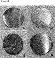
- FIG. 10 is a diagram showing the observation results.
- a in the left panel of FIG. 10 represents an initial state of a pole plate formed of the active material prepared in Comparative Example 1
- B in the left panel of FIG. 10 represents a state of the pole plate after the charge/discharge test.
- a in the right panel of FIG. 10 represents an initial state of a pole plate formed of the active material prepared in Example 2, and B in the right panel of FIG.
- FIG. 10 represents a state of the pole plate after the charge/discharge test. As shown in FIG. 10 , it could be seen that a base material was not substantially deformed even after the pole plate formed of the active material prepared in Example 2 was charged/discharged 10 times, but a base material was severely deformed when the pole plate formed of the active material prepared in Comparative Example 1 was charged/discharged 10 times. Although not limited in theory, the active material of Comparative Example 1 including a high-intensity matrix having excellent softness was not easily broken down or milled into a powder after the repeated charge/discharge tests, which made it difficult to effectively use the cavities in the pole plate, and led to extremely severe expansion of the pole plate expansion.
- the base material was severely deformed in the pole plate formed of the active material of Comparative Example1.
- the alloy matrix having high electric conductivity and showing an embrittlement property was employed in the active material of Example 2
- deformation of the base material was considered to be suppressed since the active material was broken down during the charge/discharge tests and fine powder of the active material was re-arranged into the cavities in the pole plate.
Landscapes
- Chemical & Material Sciences (AREA)
- Chemical Kinetics & Catalysis (AREA)
- Electrochemistry (AREA)
- General Chemical & Material Sciences (AREA)
- Engineering & Computer Science (AREA)
- Inorganic Chemistry (AREA)
- Materials Engineering (AREA)
- Composite Materials (AREA)
- Manufacturing & Machinery (AREA)
- Battery Electrode And Active Subsutance (AREA)
- Secondary Cells (AREA)
Claims (10)
- Matériau actif d'électrode négative, comprenant :une phase A comprenant un silicium actif ; etune phase B comprenant une matrice en alliage métallique comprenant un silicium et un métal de transition,dans lequel les pics différents d'un pic dérivé du silicium actif de la phase A observé par analyse XRD ex situ avant un chargement et un déchargement sont également observés par analyse XRD ex situ après le chargement et le déchargement, satisfaisant l'expression 1 suivante :
 dans laquelle le « X » représente la dureté de Vickers de la matrice en alliage, mesurée à 100 gf,dans lequel la phase A et la phase B se présente sous la forme d'un alliage,caractérisé en ce que le matériau actif d'électrode négative est représenté par la formule 1 suivante :
- Matériau actif d'électrode négative selon la revendication 1, dans lequel, dans la formule 1, le « a » va de 30 % atomique à 80 % atomique, le « b » va de 10 % atomique à 35 % atomique, et le « c » va de 10 % atomique à 35 % atomique.
- Matériau actif d'électrode négative selon la revendication 1, dans lequel la phase A est constituée d'une monophase de silicium actif.
- Matériau actif d'électrode négative selon la revendication 1, dans lequel le silicium actif de la phase A possède un diamètre moyen de particules de 1000 nm ou moins.
- Matériau actif d'électrode négative selon la revendication 1, dans lequel le « X » est de 800 Hv ou plus.
- Matériau actif d'électrode négative selon la revendication 1, dont une conductivité électrique mesurée à une charge de 20 kN est de 5 x 101 S/cm ou plus.
- Batterie secondaire comprenant :une électrode positive ;une électrode négative comprenant le matériau actif selon la revendication 1 ; etun électrolyte.
- Batterie secondaire selon la revendication 7, dans laquelle l'électrode positive comprend un composé d'intercalage lithiaté, un soufre élémentaire ou un composé soufré.
- Batterie secondaire selon la revendication 7, dans laquelle l'électrolyte comprend un solvant organique non aqueux et un sel de lithium.
- Batterie secondaire selon la revendication 7, qui prend une forme de tube, de cor, de pièce de monnaie ou de poche.
Applications Claiming Priority (2)
| Application Number | Priority Date | Filing Date | Title |
|---|---|---|---|
| KR1020100074314A KR101263265B1 (ko) | 2010-07-30 | 2010-07-30 | 음극 활물질 |
| PCT/KR2010/008183 WO2012015105A1 (fr) | 2010-07-30 | 2010-11-19 | Matériau actif de cathode |
Publications (3)
| Publication Number | Publication Date |
|---|---|
| EP2600446A1 EP2600446A1 (fr) | 2013-06-05 |
| EP2600446A4 EP2600446A4 (fr) | 2014-12-17 |
| EP2600446B1 true EP2600446B1 (fr) | 2017-03-29 |
Family
ID=45530289
Family Applications (1)
| Application Number | Title | Priority Date | Filing Date |
|---|---|---|---|
| EP10855377.7A Active EP2600446B1 (fr) | 2010-07-30 | 2010-11-19 | Matériau actif négatif |
Country Status (5)
| Country | Link |
|---|---|
| US (1) | US8785038B2 (fr) |
| EP (1) | EP2600446B1 (fr) |
| JP (1) | JP5554839B2 (fr) |
| KR (1) | KR101263265B1 (fr) |
| WO (1) | WO2012015105A1 (fr) |
Families Citing this family (14)
| Publication number | Priority date | Publication date | Assignee | Title |
|---|---|---|---|---|
| CN103702589A (zh) | 2011-03-30 | 2014-04-02 | 徐俊 | 可折叠书架 |
| JP2012238399A (ja) * | 2011-05-09 | 2012-12-06 | Gs Yuasa Corp | 非水電解質二次電池用電極材料、非水電解質二次電池用電極及び非水電解質二次電池 |
| US9716264B2 (en) * | 2012-02-21 | 2017-07-25 | Samsung Sdi Co., Ltd. | Electrode for lithium secondary battery, method of manufacturing the electrode, and lithium secondary battery including the electrode |
| JPWO2015064633A1 (ja) * | 2013-10-30 | 2017-03-09 | 古河電気工業株式会社 | 負極活物質及びその製造方法並びにそれを用いた負極及び非水電解質二次電池 |
| KR20150074905A (ko) | 2013-12-24 | 2015-07-02 | 일진전기 주식회사 | 리튬 이차 전지용 음극 활물질 |
| KR101620849B1 (ko) * | 2014-01-20 | 2016-05-13 | 일진전기 주식회사 | 리튬 이차 전지용 음극 활물질 |
| KR102152883B1 (ko) * | 2014-01-27 | 2020-09-07 | 삼성에스디아이 주식회사 | 음극 활물질, 이를 채용한 음극과 리튬 전지, 및 상기 음극 활물질의 제조방법 |
| JP6384144B2 (ja) * | 2014-06-23 | 2018-09-05 | 株式会社デンソー | 電極活物質,電極及び電池 |
| JP6032501B2 (ja) * | 2014-07-23 | 2016-11-30 | 株式会社Gsユアサ | 非水電解質二次電池用電極材料及び非水電解質二次電池 |
| EP3236520B1 (fr) * | 2014-12-17 | 2019-10-02 | Nissan Motor Co., Ltd. | Matériau actif d'électrode négative pour un dispositif électrique et dispositif électrique l'utilisant |
| KR102727435B1 (ko) | 2015-06-22 | 2024-11-07 | 일진전기 주식회사 | 이차전지용 음극활물질 및 그의 제조방법 |
| WO2017040690A1 (fr) * | 2015-09-02 | 2017-03-09 | Estimote, Inc. | Système et procédés de suivi d'objet avec des balises sans fil |
| US11670772B2 (en) * | 2017-11-30 | 2023-06-06 | Panasonic Intellectual Property Management Co., Ltd. | Negative electrode active material for lithium ion battery, and lithium ion battery |
| KR102901230B1 (ko) | 2020-10-08 | 2025-12-16 | 유미코아 | 탄소질 매트릭스 입자의 분말 및 이러한 분말을 포함하는 배터리 음극에 사용하기 위한 복합 분말 |
Family Cites Families (13)
| Publication number | Priority date | Publication date | Assignee | Title |
|---|---|---|---|---|
| EP1573835B1 (fr) * | 2002-11-26 | 2017-05-03 | Showa Denko K.K. | Matériau d'éléctrode, comprenant des particules de silicium et/ou d'étain, et procédé de production et utilisation de celui-ci |
| KR100563081B1 (ko) * | 2003-04-28 | 2006-03-27 | 강원대학교산학협력단 | 리튬 이차 전지용 음극 박막 및 그의 제조 방법 |
| US7955735B2 (en) * | 2004-11-15 | 2011-06-07 | Panasonic Corporation | Non-aqueous electrolyte secondary battery |
| JP5030414B2 (ja) | 2004-11-15 | 2012-09-19 | パナソニック株式会社 | 非水電解質二次電池 |
| KR101281277B1 (ko) * | 2005-03-23 | 2013-07-03 | 파이오닉스 가부시키가이샤 | 리튬이차전지용 음극 활물질 입자 및 음극의 제조 방법 |
| JP4831987B2 (ja) | 2005-03-31 | 2011-12-07 | 三洋電機株式会社 | 非水電解液二次電池の製造方法 |
| US7923150B2 (en) * | 2005-08-26 | 2011-04-12 | Panasonic Corporation | Non-aqueous electrolyte secondary battery |
| JP4994631B2 (ja) * | 2005-10-12 | 2012-08-08 | パナソニック株式会社 | 非水電解質二次電池およびその正極活物質 |
| JP5072323B2 (ja) * | 2005-11-17 | 2012-11-14 | パナソニック株式会社 | 非水電解質二次電池、および非水電解質二次電池用負極材料の製造方法 |
| KR100949330B1 (ko) * | 2005-11-29 | 2010-03-26 | 삼성에스디아이 주식회사 | 리튬 이차 전지용 음극 활물질 및 그를 포함하는 리튬 이차전지 |
| JP5200339B2 (ja) * | 2006-06-16 | 2013-06-05 | パナソニック株式会社 | 非水電解質二次電池 |
| KR100814816B1 (ko) * | 2006-11-27 | 2008-03-20 | 삼성에스디아이 주식회사 | 리튬 이차 전지용 음극 활물질 및 그를 포함하는 리튬 이차전지 |
| JP5761758B2 (ja) * | 2008-12-30 | 2015-08-12 | エルジー・ケム・リミテッド | 二次電池用アノード活物質 |
-
2010
- 2010-07-30 KR KR1020100074314A patent/KR101263265B1/ko active Active
- 2010-11-19 WO PCT/KR2010/008183 patent/WO2012015105A1/fr not_active Ceased
- 2010-11-19 US US13/813,018 patent/US8785038B2/en active Active
- 2010-11-19 EP EP10855377.7A patent/EP2600446B1/fr active Active
- 2010-11-19 JP JP2012526674A patent/JP5554839B2/ja active Active
Also Published As
| Publication number | Publication date |
|---|---|
| JP2012527741A (ja) | 2012-11-08 |
| US20130130101A1 (en) | 2013-05-23 |
| WO2012015105A1 (fr) | 2012-02-02 |
| KR20120012265A (ko) | 2012-02-09 |
| KR101263265B1 (ko) | 2013-05-10 |
| EP2600446A1 (fr) | 2013-06-05 |
| US8785038B2 (en) | 2014-07-22 |
| JP5554839B2 (ja) | 2014-07-23 |
| EP2600446A4 (fr) | 2014-12-17 |
Similar Documents
| Publication | Publication Date | Title |
|---|---|---|
| EP2600446B1 (fr) | Matériau actif négatif | |
| KR100859687B1 (ko) | 리튬 이차 전지용 음극 활물질 및 그를 포함하는 리튬 이차전지 | |
| EP1928046B1 (fr) | Matériau actif négatif et batterie au lithium rechargeable l'incorporant | |
| EP3647269A1 (fr) | Matériau actif positif pour batterie au lithium rechargeable, son procédé de préparation et batterie au lithium rechargeable le comprenant | |
| US9882210B2 (en) | Composite anode materials for lithium ion batteries | |
| EP1791200B1 (fr) | Matériau actif négatif et pile rechargeable au lithium contenant matériau actif négatif | |
| EP2626931A1 (fr) | Matériau actif négatif pour batterie au lithium rechargeable et batterie au lithium rechargeable l'incluant | |
| US20140332716A1 (en) | Anode active material for secondary battery, and secondary battery including same | |
| US10446839B2 (en) | Positive active material for rechargeable lithium battery, method of manufacturing the same, and rechargeable lithium battery including the same | |
| Wang et al. | Synthesis and electrochemistry properties of Sn–Sb ultrafine particles as anode of lithium-ion batteries | |
| EP3224885B1 (fr) | Matériau actif négatif pour batterie secondaire et batterie secondaire utilisant celui-ci | |
| KR100786864B1 (ko) | 리튬 이차 전지용 음극 활물질, 그의 제조 방법 및 그를포함하는 리튬 이차 전지 | |
| Wang et al. | Nanosized Si–Ni alloys anode prepared by hydrogen plasma–metal reaction for secondary lithium batteries | |
| Guo et al. | A novel SnxSbNi composite as anode materials for Li rechargeable batteries | |
| KR101492973B1 (ko) | 리튬 이차 전지용 음극활물질 및 이를 이용한 이차전지 | |
| KR101490559B1 (ko) | 음극활물질용 복합금속 제조방법 | |
| KR100637488B1 (ko) | 리튬 이차 전지용 음극 활물질 및 이를 포함하는 리튬 이차전지 | |
| EP3243237B9 (fr) | Matériau actif négatif pour batterie rechargeable, et batterie rechargeable l'utilisant | |
| KR101492970B1 (ko) | 리튬 이차 전지용 음극활물질 | |
| KR20160062774A (ko) | 이차전지용 음극활물질 및 이를 이용한 이차전지 | |
| KR101734838B1 (ko) | 이차전지용 음극활물질 및 이를 이용한 이차전지 | |
| US20250210695A1 (en) | Anode-solid electrolyte sub-assembly for solid secondary battery, solid secondary battery including the same, and method of manufacturing the solid secondary battery | |
| KR20140080579A (ko) | 리튬 이차 전지용 음극활물질 | |
| Monconduit et al. | An Optimized Electrically Conductive Si-Fe Matrix to Boost the Performance of Si Electrodes in Li-Ion Batteries | |
| KR20250056701A (ko) | 음극 활물질, 이의 제조 방법 및 이를 포함하는 리튬 이차 전지 |
Legal Events
| Date | Code | Title | Description |
|---|---|---|---|
| PUAI | Public reference made under article 153(3) epc to a published international application that has entered the european phase |
Free format text: ORIGINAL CODE: 0009012 |
|
| 17P | Request for examination filed |
Effective date: 20130228 |
|
| AK | Designated contracting states |
Kind code of ref document: A1 Designated state(s): AL AT BE BG CH CY CZ DE DK EE ES FI FR GB GR HR HU IE IS IT LI LT LU LV MC MK MT NL NO PL PT RO RS SE SI SK SM TR |
|
| DAX | Request for extension of the european patent (deleted) | ||
| A4 | Supplementary search report drawn up and despatched |
Effective date: 20141117 |
|
| RIC1 | Information provided on ipc code assigned before grant |
Ipc: H01M 10/05 20100101ALI20141111BHEP Ipc: H01M 10/0525 20100101ALI20141111BHEP Ipc: H01M 4/36 20060101ALI20141111BHEP Ipc: H01M 4/134 20100101ALI20141111BHEP Ipc: H01M 4/38 20060101AFI20141111BHEP |
|
| GRAP | Despatch of communication of intention to grant a patent |
Free format text: ORIGINAL CODE: EPIDOSNIGR1 |
|
| RIC1 | Information provided on ipc code assigned before grant |
Ipc: H01M 4/38 20060101AFI20161013BHEP Ipc: H01M 4/36 20060101ALI20161013BHEP Ipc: H01M 4/134 20100101ALI20161013BHEP Ipc: H01M 4/525 20100101ALI20161013BHEP Ipc: H01M 10/05 20100101ALI20161013BHEP Ipc: H01M 4/58 20060101ALI20161013BHEP Ipc: H01M 10/0525 20100101ALI20161013BHEP |
|
| INTG | Intention to grant announced |
Effective date: 20161115 |
|
| GRAS | Grant fee paid |
Free format text: ORIGINAL CODE: EPIDOSNIGR3 |
|
| GRAA | (expected) grant |
Free format text: ORIGINAL CODE: 0009210 |
|
| AK | Designated contracting states |
Kind code of ref document: B1 Designated state(s): AL AT BE BG CH CY CZ DE DK EE ES FI FR GB GR HR HU IE IS IT LI LT LU LV MC MK MT NL NO PL PT RO RS SE SI SK SM TR |
|
| REG | Reference to a national code |
Ref country code: GB Ref legal event code: FG4D |
|
| REG | Reference to a national code |
Ref country code: CH Ref legal event code: EP |
|
| REG | Reference to a national code |
Ref country code: AT Ref legal event code: REF Ref document number: 880519 Country of ref document: AT Kind code of ref document: T Effective date: 20170415 |
|
| REG | Reference to a national code |
Ref country code: IE Ref legal event code: FG4D |
|
| REG | Reference to a national code |
Ref country code: DE Ref legal event code: R096 Ref document number: 602010041207 Country of ref document: DE |
|
| PG25 | Lapsed in a contracting state [announced via postgrant information from national office to epo] |
Ref country code: NO Free format text: LAPSE BECAUSE OF FAILURE TO SUBMIT A TRANSLATION OF THE DESCRIPTION OR TO PAY THE FEE WITHIN THE PRESCRIBED TIME-LIMIT Effective date: 20170629 Ref country code: LT Free format text: LAPSE BECAUSE OF FAILURE TO SUBMIT A TRANSLATION OF THE DESCRIPTION OR TO PAY THE FEE WITHIN THE PRESCRIBED TIME-LIMIT Effective date: 20170329 Ref country code: HR Free format text: LAPSE BECAUSE OF FAILURE TO SUBMIT A TRANSLATION OF THE DESCRIPTION OR TO PAY THE FEE WITHIN THE PRESCRIBED TIME-LIMIT Effective date: 20170329 Ref country code: FI Free format text: LAPSE BECAUSE OF FAILURE TO SUBMIT A TRANSLATION OF THE DESCRIPTION OR TO PAY THE FEE WITHIN THE PRESCRIBED TIME-LIMIT Effective date: 20170329 Ref country code: GR Free format text: LAPSE BECAUSE OF FAILURE TO SUBMIT A TRANSLATION OF THE DESCRIPTION OR TO PAY THE FEE WITHIN THE PRESCRIBED TIME-LIMIT Effective date: 20170630 |
|
| REG | Reference to a national code |
Ref country code: NL Ref legal event code: MP Effective date: 20170329 |
|
| REG | Reference to a national code |
Ref country code: AT Ref legal event code: MK05 Ref document number: 880519 Country of ref document: AT Kind code of ref document: T Effective date: 20170329 |
|
| PG25 | Lapsed in a contracting state [announced via postgrant information from national office to epo] |
Ref country code: SE Free format text: LAPSE BECAUSE OF FAILURE TO SUBMIT A TRANSLATION OF THE DESCRIPTION OR TO PAY THE FEE WITHIN THE PRESCRIBED TIME-LIMIT Effective date: 20170329 Ref country code: RS Free format text: LAPSE BECAUSE OF FAILURE TO SUBMIT A TRANSLATION OF THE DESCRIPTION OR TO PAY THE FEE WITHIN THE PRESCRIBED TIME-LIMIT Effective date: 20170329 Ref country code: BG Free format text: LAPSE BECAUSE OF FAILURE TO SUBMIT A TRANSLATION OF THE DESCRIPTION OR TO PAY THE FEE WITHIN THE PRESCRIBED TIME-LIMIT Effective date: 20170629 Ref country code: LV Free format text: LAPSE BECAUSE OF FAILURE TO SUBMIT A TRANSLATION OF THE DESCRIPTION OR TO PAY THE FEE WITHIN THE PRESCRIBED TIME-LIMIT Effective date: 20170329 |
|
| REG | Reference to a national code |
Ref country code: FR Ref legal event code: PLFP Year of fee payment: 8 |
|
| PG25 | Lapsed in a contracting state [announced via postgrant information from national office to epo] |
Ref country code: NL Free format text: LAPSE BECAUSE OF FAILURE TO SUBMIT A TRANSLATION OF THE DESCRIPTION OR TO PAY THE FEE WITHIN THE PRESCRIBED TIME-LIMIT Effective date: 20170329 |
|
| PG25 | Lapsed in a contracting state [announced via postgrant information from national office to epo] |
Ref country code: EE Free format text: LAPSE BECAUSE OF FAILURE TO SUBMIT A TRANSLATION OF THE DESCRIPTION OR TO PAY THE FEE WITHIN THE PRESCRIBED TIME-LIMIT Effective date: 20170329 Ref country code: IT Free format text: LAPSE BECAUSE OF FAILURE TO SUBMIT A TRANSLATION OF THE DESCRIPTION OR TO PAY THE FEE WITHIN THE PRESCRIBED TIME-LIMIT Effective date: 20170329 Ref country code: RO Free format text: LAPSE BECAUSE OF FAILURE TO SUBMIT A TRANSLATION OF THE DESCRIPTION OR TO PAY THE FEE WITHIN THE PRESCRIBED TIME-LIMIT Effective date: 20170329 Ref country code: CZ Free format text: LAPSE BECAUSE OF FAILURE TO SUBMIT A TRANSLATION OF THE DESCRIPTION OR TO PAY THE FEE WITHIN THE PRESCRIBED TIME-LIMIT Effective date: 20170329 Ref country code: SK Free format text: LAPSE BECAUSE OF FAILURE TO SUBMIT A TRANSLATION OF THE DESCRIPTION OR TO PAY THE FEE WITHIN THE PRESCRIBED TIME-LIMIT Effective date: 20170329 Ref country code: AT Free format text: LAPSE BECAUSE OF FAILURE TO SUBMIT A TRANSLATION OF THE DESCRIPTION OR TO PAY THE FEE WITHIN THE PRESCRIBED TIME-LIMIT Effective date: 20170329 Ref country code: ES Free format text: LAPSE BECAUSE OF FAILURE TO SUBMIT A TRANSLATION OF THE DESCRIPTION OR TO PAY THE FEE WITHIN THE PRESCRIBED TIME-LIMIT Effective date: 20170329 |
|
| PG25 | Lapsed in a contracting state [announced via postgrant information from national office to epo] |
Ref country code: PT Free format text: LAPSE BECAUSE OF FAILURE TO SUBMIT A TRANSLATION OF THE DESCRIPTION OR TO PAY THE FEE WITHIN THE PRESCRIBED TIME-LIMIT Effective date: 20170731 Ref country code: IS Free format text: LAPSE BECAUSE OF FAILURE TO SUBMIT A TRANSLATION OF THE DESCRIPTION OR TO PAY THE FEE WITHIN THE PRESCRIBED TIME-LIMIT Effective date: 20170729 Ref country code: SM Free format text: LAPSE BECAUSE OF FAILURE TO SUBMIT A TRANSLATION OF THE DESCRIPTION OR TO PAY THE FEE WITHIN THE PRESCRIBED TIME-LIMIT Effective date: 20170329 Ref country code: PL Free format text: LAPSE BECAUSE OF FAILURE TO SUBMIT A TRANSLATION OF THE DESCRIPTION OR TO PAY THE FEE WITHIN THE PRESCRIBED TIME-LIMIT Effective date: 20170329 |
|
| REG | Reference to a national code |
Ref country code: DE Ref legal event code: R097 Ref document number: 602010041207 Country of ref document: DE |
|
| PG25 | Lapsed in a contracting state [announced via postgrant information from national office to epo] |
Ref country code: DK Free format text: LAPSE BECAUSE OF FAILURE TO SUBMIT A TRANSLATION OF THE DESCRIPTION OR TO PAY THE FEE WITHIN THE PRESCRIBED TIME-LIMIT Effective date: 20170329 |
|
| PLBE | No opposition filed within time limit |
Free format text: ORIGINAL CODE: 0009261 |
|
| STAA | Information on the status of an ep patent application or granted ep patent |
Free format text: STATUS: NO OPPOSITION FILED WITHIN TIME LIMIT |
|
| 26N | No opposition filed |
Effective date: 20180103 |
|
| PG25 | Lapsed in a contracting state [announced via postgrant information from national office to epo] |
Ref country code: SI Free format text: LAPSE BECAUSE OF FAILURE TO SUBMIT A TRANSLATION OF THE DESCRIPTION OR TO PAY THE FEE WITHIN THE PRESCRIBED TIME-LIMIT Effective date: 20170329 |
|
| PG25 | Lapsed in a contracting state [announced via postgrant information from national office to epo] |
Ref country code: MC Free format text: LAPSE BECAUSE OF FAILURE TO SUBMIT A TRANSLATION OF THE DESCRIPTION OR TO PAY THE FEE WITHIN THE PRESCRIBED TIME-LIMIT Effective date: 20170329 |
|
| PG25 | Lapsed in a contracting state [announced via postgrant information from national office to epo] |
Ref country code: LI Free format text: LAPSE BECAUSE OF NON-PAYMENT OF DUE FEES Effective date: 20171130 Ref country code: CH Free format text: LAPSE BECAUSE OF NON-PAYMENT OF DUE FEES Effective date: 20171130 |
|
| PG25 | Lapsed in a contracting state [announced via postgrant information from national office to epo] |
Ref country code: LU Free format text: LAPSE BECAUSE OF NON-PAYMENT OF DUE FEES Effective date: 20171119 |
|
| REG | Reference to a national code |
Ref country code: BE Ref legal event code: MM Effective date: 20171130 |
|
| REG | Reference to a national code |
Ref country code: IE Ref legal event code: MM4A |
|
| REG | Reference to a national code |
Ref country code: FR Ref legal event code: PLFP Year of fee payment: 9 |
|
| PG25 | Lapsed in a contracting state [announced via postgrant information from national office to epo] |
Ref country code: MT Free format text: LAPSE BECAUSE OF NON-PAYMENT OF DUE FEES Effective date: 20171119 |
|
| PG25 | Lapsed in a contracting state [announced via postgrant information from national office to epo] |
Ref country code: IE Free format text: LAPSE BECAUSE OF NON-PAYMENT OF DUE FEES Effective date: 20171119 |
|
| PG25 | Lapsed in a contracting state [announced via postgrant information from national office to epo] |
Ref country code: BE Free format text: LAPSE BECAUSE OF NON-PAYMENT OF DUE FEES Effective date: 20171130 |
|
| PG25 | Lapsed in a contracting state [announced via postgrant information from national office to epo] |
Ref country code: HU Free format text: LAPSE BECAUSE OF FAILURE TO SUBMIT A TRANSLATION OF THE DESCRIPTION OR TO PAY THE FEE WITHIN THE PRESCRIBED TIME-LIMIT; INVALID AB INITIO Effective date: 20101119 |
|
| PG25 | Lapsed in a contracting state [announced via postgrant information from national office to epo] |
Ref country code: CY Free format text: LAPSE BECAUSE OF NON-PAYMENT OF DUE FEES Effective date: 20170329 |
|
| PG25 | Lapsed in a contracting state [announced via postgrant information from national office to epo] |
Ref country code: MK Free format text: LAPSE BECAUSE OF FAILURE TO SUBMIT A TRANSLATION OF THE DESCRIPTION OR TO PAY THE FEE WITHIN THE PRESCRIBED TIME-LIMIT Effective date: 20170329 |
|
| PG25 | Lapsed in a contracting state [announced via postgrant information from national office to epo] |
Ref country code: TR Free format text: LAPSE BECAUSE OF FAILURE TO SUBMIT A TRANSLATION OF THE DESCRIPTION OR TO PAY THE FEE WITHIN THE PRESCRIBED TIME-LIMIT Effective date: 20170329 |
|
| PG25 | Lapsed in a contracting state [announced via postgrant information from national office to epo] |
Ref country code: AL Free format text: LAPSE BECAUSE OF FAILURE TO SUBMIT A TRANSLATION OF THE DESCRIPTION OR TO PAY THE FEE WITHIN THE PRESCRIBED TIME-LIMIT Effective date: 20170329 |
|
| PGFP | Annual fee paid to national office [announced via postgrant information from national office to epo] |
Ref country code: GB Payment date: 20250922 Year of fee payment: 16 |
|
| PGFP | Annual fee paid to national office [announced via postgrant information from national office to epo] |
Ref country code: FR Payment date: 20250925 Year of fee payment: 16 |
|
| PGFP | Annual fee paid to national office [announced via postgrant information from national office to epo] |
Ref country code: DE Payment date: 20250922 Year of fee payment: 16 |