EP2600472B1 - Connecteur de bus en série universel - Google Patents
Connecteur de bus en série universel Download PDFInfo
- Publication number
- EP2600472B1 EP2600472B1 EP12157641.7A EP12157641A EP2600472B1 EP 2600472 B1 EP2600472 B1 EP 2600472B1 EP 12157641 A EP12157641 A EP 12157641A EP 2600472 B1 EP2600472 B1 EP 2600472B1
- Authority
- EP
- European Patent Office
- Prior art keywords
- shell
- usb connector
- usb
- connector
- conductive terminal
- Prior art date
- Legal status (The legal status is an assumption and is not a legal conclusion. Google has not performed a legal analysis and makes no representation as to the accuracy of the status listed.)
- Not-in-force
Links
- 239000011810 insulating material Substances 0.000 claims description 2
- 239000002184 metal Substances 0.000 claims description 2
- 230000005540 biological transmission Effects 0.000 description 6
- 230000037431 insertion Effects 0.000 description 2
- 238000003780 insertion Methods 0.000 description 2
- 230000009286 beneficial effect Effects 0.000 description 1
- 230000002457 bidirectional effect Effects 0.000 description 1
- 230000001419 dependent effect Effects 0.000 description 1
- 239000006260 foam Substances 0.000 description 1
- 239000000463 material Substances 0.000 description 1
Images


Classifications
-
- H—ELECTRICITY
- H01—ELECTRIC ELEMENTS
- H01R—ELECTRICALLY-CONDUCTIVE CONNECTIONS; STRUCTURAL ASSOCIATIONS OF A PLURALITY OF MUTUALLY-INSULATED ELECTRICAL CONNECTING ELEMENTS; COUPLING DEVICES; CURRENT COLLECTORS
- H01R27/00—Coupling parts adapted for co-operation with two or more dissimilar counterparts
-
- H—ELECTRICITY
- H01—ELECTRIC ELEMENTS
- H01R—ELECTRICALLY-CONDUCTIVE CONNECTIONS; STRUCTURAL ASSOCIATIONS OF A PLURALITY OF MUTUALLY-INSULATED ELECTRICAL CONNECTING ELEMENTS; COUPLING DEVICES; CURRENT COLLECTORS
- H01R13/00—Details of coupling devices of the kinds covered by groups H01R12/70 or H01R24/00 - H01R33/00
- H01R13/64—Means for preventing incorrect coupling
-
- H—ELECTRICITY
- H01—ELECTRIC ELEMENTS
- H01R—ELECTRICALLY-CONDUCTIVE CONNECTIONS; STRUCTURAL ASSOCIATIONS OF A PLURALITY OF MUTUALLY-INSULATED ELECTRICAL CONNECTING ELEMENTS; COUPLING DEVICES; CURRENT COLLECTORS
- H01R24/00—Two-part coupling devices, or either of their cooperating parts, characterised by their overall structure
- H01R24/60—Contacts spaced along planar side wall transverse to longitudinal axis of engagement
- H01R24/62—Sliding engagements with one side only, e.g. modular jack coupling devices
Definitions
- This invention is relative to a universal serial bus (USB) connector which can be plugged with both sides.
- USB universal serial bus
- USB Universal serial bus
- USB is a transmission protocol which is widely accepted and has been adopted recently. Since USB is characterized by high transmission rate, USB connection ports become necessary for most computers and laptops and the corresponding drivers of USB are also built in those computers and laptops in advance. Besides, because the transmission of USB can be activated by just one plug-and-play step, USB has become the transmission protocol for a variety of electronic devices, such as flash drives, portable hard drives, mp3 players or portable CD-ROM drives. In other words, the USB connector along with its transmission protocol is a must-have unit of the electronic device.
- the common USB connector can just be plugged on one side, the body and the conductive terminal inside the connector are arranged correspondingly. If the USB connector is inserted upside down, it can not work successfully and may be even damaged.
- the positive side of the USB connector is usually labeled by a reminder icon to prevent the wrong insertion.
- the USB ports of some electronic devices are set in a reverse direction to be complied with the layout of the internal components. Under this condition, the user cannot insert the USB connector successfully following the reminder icon, thereby causing inconvenience.
- US 2006/024997 A1 and WO 2005/013436 A1 also disclose a USB device and connector including a shell and body disposed within the shell.
- a USB connector if the USB connector is inserted upside down, it cannot work successfully and may be even damaged. Therefore, these prior arts encounter troublesome and inconvenient as the aforesaid problem.
- US 6 981 887 B1 discloses a USB receptacle including a bidirectional backplane that permits electrical contacts within the receptacle to slide or move in a direction that is perpendicular to the linear direction of the connector and its connecting cables.
- An orientation sensor may be used such as a pressure transducer which serves to detect the orientation of the plug with respect to the receptacle.
- a multi-layer printed circuit board may be used to cross or reverse the pins in the plug, such as D+ to D- and Power to Ground.
- an object of the present invention is to provide an USB connector which can be inserted with both sides for solving the aforesaid problems of the conventional USB connector and increasing user's convenience.
- a universal serial bus (USB) connector includes a shell, a body and an elastic portion.
- the body is provided inside the shell and can be moved therein.
- the body includes a first conductive terminal provided on a first surface and a second conductive terminal provided on a second surface.
- the elastic portion is connected to both leading edges of the first surface and the second surface for keeping the body in position inside the shell.
- the USB connector comprises an elastic portion which is composed of two parts located on the first surface and the second surface of the body respectively, each of the two parts of the elastic portion comprises a fixation piece and an elastic piece.
- the fixation pieces are connected to the first surface and the second surface respectively, and each of the elastic pieces is connected with the corresponding fixation piece and enables the body to move inside the shell such that the elastic portion retains the body in position inside the shell by using spring force;
- the USB connector can be inserted with both sides and electrically connected to the first conductive terminal on the first surface or to the second conductive terminal on the second surface.
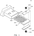
- the USB connector 10 of the present invention includes a shell 101, a body 102 and an elastic portion 103.
- the body 102 is disposed within the shell 101 and the initial position of the body 102 is located in middle of the shell 101.
- the body 102 has a first surface 1021and a second surface 1023 which are disposed on opposite side of the body 102.
- the body 102 has a first conductive terminal 1022 and a second conductive terminal 1024.
- the first conductive terminal 1022 and the second conductive terminal 1024 are provided on the first surface 1021 and the second surface 1023 of the body 102 respectively.
- first conductive terminal 1022 and the second conductive terminal 1024 are configured following the technical specifications of the USB transmission protocol, and both of them can be electrically connected to USB port alternatively and operated independently.
- the shell 101 is made of metal while the body 102 is made of an insulating material.
- the elastic portion 103 is composed of two parts located on both sides of the body 102 respectively.
- Each of the two parts of the elastic portion 103 has a fixation piece 1031 and an elastic piece 1032.
- Leading edges of both fixation pieces 1031 are rounded to be an arc profile and connected to the first surface 1021 and second surface 1023 of the body 102 respectively.
- the elastic piece 1032 is also connected with the fixation piece 1031 and enables the body 102 to move in the space inside the shell 101.
- the elastic piece 1032 could be flexible foam. It is noted that one with ordinary skill in the art can employ other materials for the elastic piece 1032 as required.
- the USB connector 10 further includes an insulating shell 105.
- the insulating shell 105 covers the shell 101 and could be formed integrally therewith for facilitating the plug-in or pull-out of the USB connector 10.
- FIGs. 4 and 5 are respectively a schematic view and a side view of the USB connector according to one embodiment of the present invention when plugged into an electronic device.
- the elastic piece 1032 and the fixation pieces 1031 located in the leading edge of the body 102 contact first with the USB port 20 through the opening as illustrated in FIG. 4 .
- the conductive pin 201 is provided extending to the level below the USB port 20 as illustrated in FIG. 5 , the elastic piece 1032 under the body 102 will be squeezed, and then the fixation pieces 1031 and the body 102 connected with the fixation pieces 1031 will move upward in the shell 101.
- FIG. 6 illustrates a side view of the USB connector according to another embodiment of the present invention when plugged into an electronic device. On the contrary, if the conductive pin 201 is provided extending to the level above the USB port 20 as illustrated in FIG.
- the elastic piece 1032 above the body 102 will be squeezed, and then the fixation pieces 1031 and the body 102 connected with the fixation pieces 1031 will move downward in the shell 101.
- the elastic pieces 1032 and the fixation pieces 1031 pass through the conductive pin 201, the elastic pieces 1032 and the fixation pieces 1031 of the body 102 will be held in position within the USB port 20 to make the first terminal 1022 on the first surface 1021 of the body 102 be electrically connected with the conductive pin 201 while the second terminal 1024 on the second surface 1023 of the body 102 will not be conductive comparatively.
- the USB connector of the present invention has an elastic portion and a body that can be moved up and down, thereby eliminating the concern about the plug-in direction of the USB port when connected to the electronic device. As a result, the users' convenience is significantly improved. Besides, the USB connector is protected from damage due to the incorrect insertion, which is helpful in prolonging the service life of the USB connector.
Landscapes
- Details Of Connecting Devices For Male And Female Coupling (AREA)
- Coupling Device And Connection With Printed Circuit (AREA)
Claims (6)
- Connecteur de bus en série universel USB (10) comprenant :une coque (101) ; etun corps (102) disposé à l'intérieur de la coque (101) et capable de se déplacer par rapport à la coque (101), le corps (102) comprenant une première surface (1021) et une seconde surface (1023), la première surface (1021) étant disposée à l'opposé de la seconde surface (1023), une première borne conductrice (1022) étant prévue sur la première surface (1021) et une seconde borne conductrice (1024) étant prévue sur la seconde surface (1023) ;dans lequel le connecteur USB (10) est caractérisé en ce qu'il comprend une portion élastique (103) qui est composée de deux parties situées sur la première surface (1021) et la seconde surface (1023) du corps respectivement, chacune des deux parties de la portion élastique comprend une pièce de fixation (1031) et une pièce élastique (1032), les pièces de fixation (1031) sont raccordées à la première surface (1021) et à la seconde surface (1032) respectivement, et chacune des pièces élastiques (1032) est raccordée à la pièce de fixation correspondante (1031) et permet au corps (102) de se déplacer à l'intérieur de la coque (101), de sorte que la portion élastique (103) retienne le corps (102) en position à l'intérieur de la coque (101) en utilisant une force de ressort ;dans lequel le connecteur USB (10) peut être inséré des deux côtés et connecté électriquement à la première borne conductrice (1022) sur la première surface (1021) ou à la seconde borne conductrice (1024) sur la seconde surface (1023), en éliminant ainsi un souci concernant la direction d'enfichage dans un port USB (20) lorsqu'il est connecté à un dispositif électronique, de sorte que le connecteur USB (10) soit protégé d'une insertion dans une mauvaise direction.
- Connecteur USB (10) selon la revendication 1, caractérisé en ce que le corps (102) est situé au milieu de la coque (101) initialement.
- Connecteur USB (10) selon la revendication 1, caractérisé en ce que le bord d'attaque de chacune des pièces de fixation (1031) est arrondi.
- Connecteur USB (10) selon la revendication 3, caractérisé en ce que le connecteur USB (10) comprend en outre une coque isolante (105) couvrant la coque (101) et formée en un seul tenant avec la coque (101).
- Connecteur USB (10) selon la revendication 2, caractérisé en ce que le connecteur USB (10) comprend en outre une coque isolante (105) couvrant la coque (101) et formée en un seul tenant avec la coque (101).
- Connecteur USB (10) selon la revendication 1, caractérisé en ce que la coque (10) est constituée de métal et le corps (102) est constitué de matériau isolant.
Applications Claiming Priority (1)
| Application Number | Priority Date | Filing Date | Title |
|---|---|---|---|
| TW100144535A TWI434468B (zh) | 2011-12-02 | 2011-12-02 | 通用串列滙流排連接器 |
Publications (2)
| Publication Number | Publication Date |
|---|---|
| EP2600472A1 EP2600472A1 (fr) | 2013-06-05 |
| EP2600472B1 true EP2600472B1 (fr) | 2017-12-20 |
Family
ID=45756936
Family Applications (1)
| Application Number | Title | Priority Date | Filing Date |
|---|---|---|---|
| EP12157641.7A Not-in-force EP2600472B1 (fr) | 2011-12-02 | 2012-03-01 | Connecteur de bus en série universel |
Country Status (5)
| Country | Link |
|---|---|
| US (1) | US8517752B2 (fr) |
| EP (1) | EP2600472B1 (fr) |
| JP (1) | JP2013118165A (fr) |
| CN (1) | CN103138097B (fr) |
| TW (1) | TWI434468B (fr) |
Families Citing this family (6)
| Publication number | Priority date | Publication date | Assignee | Title |
|---|---|---|---|---|
| US9882323B2 (en) * | 2014-04-14 | 2018-01-30 | Apple Inc. | Flexible connector receptacles |
| US9991640B2 (en) | 2014-04-14 | 2018-06-05 | Apple Inc. | Durable connector receptacles |
| CN205178104U (zh) * | 2015-11-26 | 2016-04-20 | 连展科技(深圳)有限公司 | 插座电连接器 |
| TWI617103B (zh) | 2016-02-29 | 2018-03-01 | Toshiba Memory Corp | Electronic machine |
| US10236609B2 (en) | 2016-09-23 | 2019-03-19 | Apple Inc. | Connectors having printed circuit board tongues with reinforced frames |
| FR3095723B1 (fr) * | 2019-05-03 | 2023-11-24 | Abderrahim Ouabbas | Connecteur receptacle femelle reversible pour connecteur prise male usb type a |
Family Cites Families (8)
| Publication number | Priority date | Publication date | Assignee | Title |
|---|---|---|---|---|
| ATE498219T1 (de) * | 2003-07-28 | 2011-02-15 | Sandisk Secure Content Solutions Inc | Elektrischer verbinder |
| EP1784896A4 (fr) * | 2004-08-02 | 2007-08-08 | Milsys Ltd | Dispositif et connecteur a bus serie universel (usb) reversibles |
| US6981887B1 (en) * | 2004-08-26 | 2006-01-03 | Lenovo (Singapore) Pte. Ltd. | Universal fit USB connector |
| WO2007000814A1 (fr) * | 2005-06-29 | 2007-01-04 | Fujitsu Limited | Connecteur, carte de circuit et appareil electronique |
| US7452225B2 (en) * | 2005-10-20 | 2008-11-18 | Hewlett-Packard Development Company, L.P. | Computer device with retractable connector |
| CN101636884A (zh) * | 2006-11-22 | 2010-01-27 | 晟碟以色列有限公司 | 可靠的可互连可反转usb连接器的系统 |
| US7537471B2 (en) * | 2006-11-22 | 2009-05-26 | Sandisk Il, Ltd. | Systems of reliably interconnectable reversible USB connectors |
| JP2010251319A (ja) * | 2009-04-15 | 2010-11-04 | Chou Hsien Tsai | 双方向電気的連接が可能なソケット構造 |
-
2011
- 2011-12-02 TW TW100144535A patent/TWI434468B/zh not_active IP Right Cessation
-
2012
- 2012-02-28 CN CN201210047886.6A patent/CN103138097B/zh not_active Expired - Fee Related
- 2012-03-01 US US13/409,925 patent/US8517752B2/en not_active Expired - Fee Related
- 2012-03-01 EP EP12157641.7A patent/EP2600472B1/fr not_active Not-in-force
- 2012-03-06 JP JP2012048655A patent/JP2013118165A/ja active Pending
Non-Patent Citations (1)
| Title |
|---|
| None * |
Also Published As
| Publication number | Publication date |
|---|---|
| TW201324977A (zh) | 2013-06-16 |
| TWI434468B (zh) | 2014-04-11 |
| CN103138097B (zh) | 2016-10-05 |
| CN103138097A (zh) | 2013-06-05 |
| JP2013118165A (ja) | 2013-06-13 |
| US8517752B2 (en) | 2013-08-27 |
| US20130143441A1 (en) | 2013-06-06 |
| EP2600472A1 (fr) | 2013-06-05 |
Similar Documents
| Publication | Publication Date | Title |
|---|---|---|
| US9461424B2 (en) | Electrical receptacle connector and electrical plug connector | |
| EP2600472B1 (fr) | Connecteur de bus en série universel | |
| US8574011B2 (en) | Electronic connector | |
| US8684753B2 (en) | Plug and electronic device with the plug | |
| TWI550967B (zh) | 雙面可用的usb連接器結構 | |
| WO2005013436A1 (fr) | Connecteur electrique | |
| CN103094801A (zh) | 可拆卸式转接器与手持装置 | |
| CN207199901U (zh) | 插座电连接器 | |
| US7165977B2 (en) | Electrical connector with flexible printed circuit board | |
| US7452231B2 (en) | Portable electronic device | |
| TWI470880B (zh) | 連接器裝置 | |
| TWM454000U (zh) | 電連接器及其組合 | |
| CN203607579U (zh) | 用于磁吸式电连接装置的对接连接器 | |
| US20150280369A1 (en) | Usb detection module | |
| CN207409738U (zh) | 电子设备 | |
| US9461408B1 (en) | Adaptor and storage device using the same | |
| US20090113103A1 (en) | Cascade type charge assembly | |
| CN204130832U (zh) | 电连接器及具有电连接器的电子装置 | |
| US8506334B2 (en) | Battery connector with lid for easy disconnect | |
| CN201450188U (zh) | 电连接器 | |
| CN105470678B (zh) | 双面可用的usb连接器结构 | |
| CN104253341B (zh) | 信号传输接头 | |
| CN202308417U (zh) | 连接器插座 | |
| CN204179332U (zh) | 插座电连接器 | |
| TWI452782B (zh) | 具有複數傳輸介面之電連接器 |
Legal Events
| Date | Code | Title | Description |
|---|---|---|---|
| PUAI | Public reference made under article 153(3) epc to a published international application that has entered the european phase |
Free format text: ORIGINAL CODE: 0009012 |
|
| AK | Designated contracting states |
Kind code of ref document: A1 Designated state(s): AL AT BE BG CH CY CZ DE DK EE ES FI FR GB GR HR HU IE IS IT LI LT LU LV MC MK MT NL NO PL PT RO RS SE SI SK SM TR |
|
| AX | Request for extension of the european patent |
Extension state: BA ME |
|
| 17P | Request for examination filed |
Effective date: 20130515 |
|
| RAP1 | Party data changed (applicant data changed or rights of an application transferred) |
Owner name: GIGA-BYTE TECHNOLOGY CO., LTD. |
|
| 17Q | First examination report despatched |
Effective date: 20160830 |
|
| GRAP | Despatch of communication of intention to grant a patent |
Free format text: ORIGINAL CODE: EPIDOSNIGR1 |
|
| STAA | Information on the status of an ep patent application or granted ep patent |
Free format text: STATUS: GRANT OF PATENT IS INTENDED |
|
| INTG | Intention to grant announced |
Effective date: 20170712 |
|
| RIN1 | Information on inventor provided before grant (corrected) |
Inventor name: HUANG, HAW-KAE Inventor name: SHIU, I CHEN |
|
| GRAS | Grant fee paid |
Free format text: ORIGINAL CODE: EPIDOSNIGR3 |
|
| GRAA | (expected) grant |
Free format text: ORIGINAL CODE: 0009210 |
|
| STAA | Information on the status of an ep patent application or granted ep patent |
Free format text: STATUS: THE PATENT HAS BEEN GRANTED |
|
| AK | Designated contracting states |
Kind code of ref document: B1 Designated state(s): AL AT BE BG CH CY CZ DE DK EE ES FI FR GB GR HR HU IE IS IT LI LT LU LV MC MK MT NL NO PL PT RO RS SE SI SK SM TR |
|
| REG | Reference to a national code |
Ref country code: GB Ref legal event code: FG4D |
|
| REG | Reference to a national code |
Ref country code: CH Ref legal event code: EP |
|
| REG | Reference to a national code |
Ref country code: IE Ref legal event code: FG4D |
|
| REG | Reference to a national code |
Ref country code: AT Ref legal event code: REF Ref document number: 957177 Country of ref document: AT Kind code of ref document: T Effective date: 20180115 |
|
| REG | Reference to a national code |
Ref country code: DE Ref legal event code: R096 Ref document number: 602012041030 Country of ref document: DE |
|
| REG | Reference to a national code |
Ref country code: NL Ref legal event code: MP Effective date: 20171220 |
|
| PG25 | Lapsed in a contracting state [announced via postgrant information from national office to epo] |
Ref country code: LT Free format text: LAPSE BECAUSE OF FAILURE TO SUBMIT A TRANSLATION OF THE DESCRIPTION OR TO PAY THE FEE WITHIN THE PRESCRIBED TIME-LIMIT Effective date: 20171220 Ref country code: FI Free format text: LAPSE BECAUSE OF FAILURE TO SUBMIT A TRANSLATION OF THE DESCRIPTION OR TO PAY THE FEE WITHIN THE PRESCRIBED TIME-LIMIT Effective date: 20171220 Ref country code: NO Free format text: LAPSE BECAUSE OF FAILURE TO SUBMIT A TRANSLATION OF THE DESCRIPTION OR TO PAY THE FEE WITHIN THE PRESCRIBED TIME-LIMIT Effective date: 20180320 Ref country code: SE Free format text: LAPSE BECAUSE OF FAILURE TO SUBMIT A TRANSLATION OF THE DESCRIPTION OR TO PAY THE FEE WITHIN THE PRESCRIBED TIME-LIMIT Effective date: 20171220 |
|
| REG | Reference to a national code |
Ref country code: LT Ref legal event code: MG4D |
|
| REG | Reference to a national code |
Ref country code: AT Ref legal event code: MK05 Ref document number: 957177 Country of ref document: AT Kind code of ref document: T Effective date: 20171220 |
|
| PG25 | Lapsed in a contracting state [announced via postgrant information from national office to epo] |
Ref country code: BG Free format text: LAPSE BECAUSE OF FAILURE TO SUBMIT A TRANSLATION OF THE DESCRIPTION OR TO PAY THE FEE WITHIN THE PRESCRIBED TIME-LIMIT Effective date: 20180320 Ref country code: GR Free format text: LAPSE BECAUSE OF FAILURE TO SUBMIT A TRANSLATION OF THE DESCRIPTION OR TO PAY THE FEE WITHIN THE PRESCRIBED TIME-LIMIT Effective date: 20180321 Ref country code: LV Free format text: LAPSE BECAUSE OF FAILURE TO SUBMIT A TRANSLATION OF THE DESCRIPTION OR TO PAY THE FEE WITHIN THE PRESCRIBED TIME-LIMIT Effective date: 20171220 Ref country code: HR Free format text: LAPSE BECAUSE OF FAILURE TO SUBMIT A TRANSLATION OF THE DESCRIPTION OR TO PAY THE FEE WITHIN THE PRESCRIBED TIME-LIMIT Effective date: 20171220 Ref country code: RS Free format text: LAPSE BECAUSE OF FAILURE TO SUBMIT A TRANSLATION OF THE DESCRIPTION OR TO PAY THE FEE WITHIN THE PRESCRIBED TIME-LIMIT Effective date: 20171220 |
|
| PG25 | Lapsed in a contracting state [announced via postgrant information from national office to epo] |
Ref country code: NL Free format text: LAPSE BECAUSE OF FAILURE TO SUBMIT A TRANSLATION OF THE DESCRIPTION OR TO PAY THE FEE WITHIN THE PRESCRIBED TIME-LIMIT Effective date: 20171220 |
|
| PG25 | Lapsed in a contracting state [announced via postgrant information from national office to epo] |
Ref country code: EE Free format text: LAPSE BECAUSE OF FAILURE TO SUBMIT A TRANSLATION OF THE DESCRIPTION OR TO PAY THE FEE WITHIN THE PRESCRIBED TIME-LIMIT Effective date: 20171220 Ref country code: CZ Free format text: LAPSE BECAUSE OF FAILURE TO SUBMIT A TRANSLATION OF THE DESCRIPTION OR TO PAY THE FEE WITHIN THE PRESCRIBED TIME-LIMIT Effective date: 20171220 Ref country code: CY Free format text: LAPSE BECAUSE OF FAILURE TO SUBMIT A TRANSLATION OF THE DESCRIPTION OR TO PAY THE FEE WITHIN THE PRESCRIBED TIME-LIMIT Effective date: 20171220 Ref country code: ES Free format text: LAPSE BECAUSE OF FAILURE TO SUBMIT A TRANSLATION OF THE DESCRIPTION OR TO PAY THE FEE WITHIN THE PRESCRIBED TIME-LIMIT Effective date: 20171220 Ref country code: SK Free format text: LAPSE BECAUSE OF FAILURE TO SUBMIT A TRANSLATION OF THE DESCRIPTION OR TO PAY THE FEE WITHIN THE PRESCRIBED TIME-LIMIT Effective date: 20171220 |
|
| PG25 | Lapsed in a contracting state [announced via postgrant information from national office to epo] |
Ref country code: PL Free format text: LAPSE BECAUSE OF FAILURE TO SUBMIT A TRANSLATION OF THE DESCRIPTION OR TO PAY THE FEE WITHIN THE PRESCRIBED TIME-LIMIT Effective date: 20171220 Ref country code: AT Free format text: LAPSE BECAUSE OF FAILURE TO SUBMIT A TRANSLATION OF THE DESCRIPTION OR TO PAY THE FEE WITHIN THE PRESCRIBED TIME-LIMIT Effective date: 20171220 Ref country code: SM Free format text: LAPSE BECAUSE OF FAILURE TO SUBMIT A TRANSLATION OF THE DESCRIPTION OR TO PAY THE FEE WITHIN THE PRESCRIBED TIME-LIMIT Effective date: 20171220 Ref country code: IS Free format text: LAPSE BECAUSE OF FAILURE TO SUBMIT A TRANSLATION OF THE DESCRIPTION OR TO PAY THE FEE WITHIN THE PRESCRIBED TIME-LIMIT Effective date: 20180420 Ref country code: RO Free format text: LAPSE BECAUSE OF FAILURE TO SUBMIT A TRANSLATION OF THE DESCRIPTION OR TO PAY THE FEE WITHIN THE PRESCRIBED TIME-LIMIT Effective date: 20171220 Ref country code: IT Free format text: LAPSE BECAUSE OF FAILURE TO SUBMIT A TRANSLATION OF THE DESCRIPTION OR TO PAY THE FEE WITHIN THE PRESCRIBED TIME-LIMIT Effective date: 20171220 |
|
| REG | Reference to a national code |
Ref country code: DE Ref legal event code: R097 Ref document number: 602012041030 Country of ref document: DE |
|
| PLBE | No opposition filed within time limit |
Free format text: ORIGINAL CODE: 0009261 |
|
| STAA | Information on the status of an ep patent application or granted ep patent |
Free format text: STATUS: NO OPPOSITION FILED WITHIN TIME LIMIT |
|
| REG | Reference to a national code |
Ref country code: CH Ref legal event code: PL |
|
| GBPC | Gb: european patent ceased through non-payment of renewal fee |
Effective date: 20180320 |
|
| 26N | No opposition filed |
Effective date: 20180921 |
|
| PG25 | Lapsed in a contracting state [announced via postgrant information from national office to epo] |
Ref country code: DK Free format text: LAPSE BECAUSE OF FAILURE TO SUBMIT A TRANSLATION OF THE DESCRIPTION OR TO PAY THE FEE WITHIN THE PRESCRIBED TIME-LIMIT Effective date: 20171220 Ref country code: MC Free format text: LAPSE BECAUSE OF FAILURE TO SUBMIT A TRANSLATION OF THE DESCRIPTION OR TO PAY THE FEE WITHIN THE PRESCRIBED TIME-LIMIT Effective date: 20171220 |
|
| REG | Reference to a national code |
Ref country code: BE Ref legal event code: MM Effective date: 20180331 |
|
| REG | Reference to a national code |
Ref country code: IE Ref legal event code: MM4A |
|
| PG25 | Lapsed in a contracting state [announced via postgrant information from national office to epo] |
Ref country code: LU Free format text: LAPSE BECAUSE OF NON-PAYMENT OF DUE FEES Effective date: 20180301 |
|
| PG25 | Lapsed in a contracting state [announced via postgrant information from national office to epo] |
Ref country code: IE Free format text: LAPSE BECAUSE OF NON-PAYMENT OF DUE FEES Effective date: 20180301 |
|
| PG25 | Lapsed in a contracting state [announced via postgrant information from national office to epo] |
Ref country code: SI Free format text: LAPSE BECAUSE OF FAILURE TO SUBMIT A TRANSLATION OF THE DESCRIPTION OR TO PAY THE FEE WITHIN THE PRESCRIBED TIME-LIMIT Effective date: 20171220 Ref country code: BE Free format text: LAPSE BECAUSE OF NON-PAYMENT OF DUE FEES Effective date: 20180331 Ref country code: GB Free format text: LAPSE BECAUSE OF NON-PAYMENT OF DUE FEES Effective date: 20180320 Ref country code: CH Free format text: LAPSE BECAUSE OF NON-PAYMENT OF DUE FEES Effective date: 20180331 Ref country code: LI Free format text: LAPSE BECAUSE OF NON-PAYMENT OF DUE FEES Effective date: 20180331 |
|
| PG25 | Lapsed in a contracting state [announced via postgrant information from national office to epo] |
Ref country code: FR Free format text: LAPSE BECAUSE OF NON-PAYMENT OF DUE FEES Effective date: 20180331 |
|
| PG25 | Lapsed in a contracting state [announced via postgrant information from national office to epo] |
Ref country code: MT Free format text: LAPSE BECAUSE OF NON-PAYMENT OF DUE FEES Effective date: 20180301 |
|
| PG25 | Lapsed in a contracting state [announced via postgrant information from national office to epo] |
Ref country code: TR Free format text: LAPSE BECAUSE OF FAILURE TO SUBMIT A TRANSLATION OF THE DESCRIPTION OR TO PAY THE FEE WITHIN THE PRESCRIBED TIME-LIMIT Effective date: 20171220 |
|
| PGFP | Annual fee paid to national office [announced via postgrant information from national office to epo] |
Ref country code: DE Payment date: 20200218 Year of fee payment: 9 |
|
| PG25 | Lapsed in a contracting state [announced via postgrant information from national office to epo] |
Ref country code: HU Free format text: LAPSE BECAUSE OF FAILURE TO SUBMIT A TRANSLATION OF THE DESCRIPTION OR TO PAY THE FEE WITHIN THE PRESCRIBED TIME-LIMIT; INVALID AB INITIO Effective date: 20120301 Ref country code: PT Free format text: LAPSE BECAUSE OF FAILURE TO SUBMIT A TRANSLATION OF THE DESCRIPTION OR TO PAY THE FEE WITHIN THE PRESCRIBED TIME-LIMIT Effective date: 20171220 |
|
| PG25 | Lapsed in a contracting state [announced via postgrant information from national office to epo] |
Ref country code: MK Free format text: LAPSE BECAUSE OF NON-PAYMENT OF DUE FEES Effective date: 20171220 |
|
| PG25 | Lapsed in a contracting state [announced via postgrant information from national office to epo] |
Ref country code: AL Free format text: LAPSE BECAUSE OF FAILURE TO SUBMIT A TRANSLATION OF THE DESCRIPTION OR TO PAY THE FEE WITHIN THE PRESCRIBED TIME-LIMIT Effective date: 20171220 |
|
| REG | Reference to a national code |
Ref country code: DE Ref legal event code: R119 Ref document number: 602012041030 Country of ref document: DE |
|
| PG25 | Lapsed in a contracting state [announced via postgrant information from national office to epo] |
Ref country code: DE Free format text: LAPSE BECAUSE OF NON-PAYMENT OF DUE FEES Effective date: 20211001 |