EP2600480B1 - Stromerzeugungsvorrichtung - Google Patents
Stromerzeugungsvorrichtung Download PDFInfo
- Publication number
- EP2600480B1 EP2600480B1 EP12007381.2A EP12007381A EP2600480B1 EP 2600480 B1 EP2600480 B1 EP 2600480B1 EP 12007381 A EP12007381 A EP 12007381A EP 2600480 B1 EP2600480 B1 EP 2600480B1
- Authority
- EP
- European Patent Office
- Prior art keywords
- power generation
- solar cell
- information
- voltage
- generation module
- Prior art date
- Legal status (The legal status is an assumption and is not a legal conclusion. Google has not performed a legal analysis and makes no representation as to the accuracy of the status listed.)
- Not-in-force
Links
Images



Classifications
-
- H—ELECTRICITY
- H02—GENERATION; CONVERSION OR DISTRIBUTION OF ELECTRIC POWER
- H02S—GENERATION OF ELECTRIC POWER BY CONVERSION OF INFRARED RADIATION, VISIBLE LIGHT OR ULTRAVIOLET LIGHT, e.g. USING PHOTOVOLTAIC [PV] MODULES
- H02S50/00—Monitoring or testing of PV systems, e.g. load balancing or fault identification
-
- G—PHYSICS
- G01—MEASURING; TESTING
- G01R—MEASURING ELECTRIC VARIABLES; MEASURING MAGNETIC VARIABLES
- G01R21/00—Arrangements for measuring electric power or power factor
-
- G—PHYSICS
- G01—MEASURING; TESTING
- G01R—MEASURING ELECTRIC VARIABLES; MEASURING MAGNETIC VARIABLES
- G01R31/00—Arrangements for testing electric properties; Arrangements for locating electric faults; Arrangements for electrical testing characterised by what is being tested not provided for elsewhere
- G01R31/40—Testing power supplies
-
- G—PHYSICS
- G06—COMPUTING OR CALCULATING; COUNTING
- G06F—ELECTRIC DIGITAL DATA PROCESSING
- G06F17/00—Digital computing or data processing equipment or methods, specially adapted for specific functions
-
- H—ELECTRICITY
- H02—GENERATION; CONVERSION OR DISTRIBUTION OF ELECTRIC POWER
- H02J—ELECTRIC POWER NETWORKS; CIRCUIT ARRANGEMENTS OR SYSTEMS FOR SUPPLYING OR DISTRIBUTING ELECTRIC POWER; SYSTEMS FOR STORING ELECTRIC ENERGY
- H02J13/00—Circuit arrangements for providing remote monitoring or remote control of equipment in a power distribution network
- H02J13/12—Monitoring network conditions, e.g. electrical magnitudes or operational status
-
- H—ELECTRICITY
- H02—GENERATION; CONVERSION OR DISTRIBUTION OF ELECTRIC POWER
- H02J—ELECTRIC POWER NETWORKS; CIRCUIT ARRANGEMENTS OR SYSTEMS FOR SUPPLYING OR DISTRIBUTING ELECTRIC POWER; SYSTEMS FOR STORING ELECTRIC ENERGY
- H02J13/00—Circuit arrangements for providing remote monitoring or remote control of equipment in a power distribution network
- H02J13/13—Circuit arrangements for providing remote monitoring or remote control of equipment in a power distribution network characterised by the transmission of data to equipment in the power network
- H02J13/1331—Circuit arrangements for providing remote monitoring or remote control of equipment in a power distribution network characterised by the transmission of data to equipment in the power network using wireless data transmission
-
- H—ELECTRICITY
- H02—GENERATION; CONVERSION OR DISTRIBUTION OF ELECTRIC POWER
- H02J—ELECTRIC POWER NETWORKS; CIRCUIT ARRANGEMENTS OR SYSTEMS FOR SUPPLYING OR DISTRIBUTING ELECTRIC POWER; SYSTEMS FOR STORING ELECTRIC ENERGY
- H02J7/00—Circuit arrangements for charging or discharging batteries or for supplying loads from batteries
- H02J7/34—Parallel operation in networks using both storage and other DC sources, e.g. providing buffering
- H02J7/35—Parallel operation in networks using both storage and other DC sources, e.g. providing buffering with light sensitive cells
-
- H—ELECTRICITY
- H02—GENERATION; CONVERSION OR DISTRIBUTION OF ELECTRIC POWER
- H02S—GENERATION OF ELECTRIC POWER BY CONVERSION OF INFRARED RADIATION, VISIBLE LIGHT OR ULTRAVIOLET LIGHT, e.g. USING PHOTOVOLTAIC [PV] MODULES
- H02S50/00—Monitoring or testing of PV systems, e.g. load balancing or fault identification
- H02S50/10—Testing of PV devices, e.g. of PV modules or single PV cells
-
- Y—GENERAL TAGGING OF NEW TECHNOLOGICAL DEVELOPMENTS; GENERAL TAGGING OF CROSS-SECTIONAL TECHNOLOGIES SPANNING OVER SEVERAL SECTIONS OF THE IPC; TECHNICAL SUBJECTS COVERED BY FORMER USPC CROSS-REFERENCE ART COLLECTIONS [XRACs] AND DIGESTS
- Y02—TECHNOLOGIES OR APPLICATIONS FOR MITIGATION OR ADAPTATION AGAINST CLIMATE CHANGE
- Y02B—CLIMATE CHANGE MITIGATION TECHNOLOGIES RELATED TO BUILDINGS, e.g. HOUSING, HOUSE APPLIANCES OR RELATED END-USER APPLICATIONS
- Y02B10/00—Integration of renewable energy sources in buildings
- Y02B10/10—Photovoltaic [PV]
-
- Y—GENERAL TAGGING OF NEW TECHNOLOGICAL DEVELOPMENTS; GENERAL TAGGING OF CROSS-SECTIONAL TECHNOLOGIES SPANNING OVER SEVERAL SECTIONS OF THE IPC; TECHNICAL SUBJECTS COVERED BY FORMER USPC CROSS-REFERENCE ART COLLECTIONS [XRACs] AND DIGESTS
- Y02—TECHNOLOGIES OR APPLICATIONS FOR MITIGATION OR ADAPTATION AGAINST CLIMATE CHANGE
- Y02B—CLIMATE CHANGE MITIGATION TECHNOLOGIES RELATED TO BUILDINGS, e.g. HOUSING, HOUSE APPLIANCES OR RELATED END-USER APPLICATIONS
- Y02B90/00—Enabling technologies or technologies with a potential or indirect contribution to GHG emissions mitigation
- Y02B90/20—Smart grids as enabling technology in buildings sector
-
- Y—GENERAL TAGGING OF NEW TECHNOLOGICAL DEVELOPMENTS; GENERAL TAGGING OF CROSS-SECTIONAL TECHNOLOGIES SPANNING OVER SEVERAL SECTIONS OF THE IPC; TECHNICAL SUBJECTS COVERED BY FORMER USPC CROSS-REFERENCE ART COLLECTIONS [XRACs] AND DIGESTS
- Y02—TECHNOLOGIES OR APPLICATIONS FOR MITIGATION OR ADAPTATION AGAINST CLIMATE CHANGE
- Y02E—REDUCTION OF GREENHOUSE GAS [GHG] EMISSIONS, RELATED TO ENERGY GENERATION, TRANSMISSION OR DISTRIBUTION
- Y02E10/00—Energy generation through renewable energy sources
- Y02E10/50—Photovoltaic [PV] energy
-
- Y—GENERAL TAGGING OF NEW TECHNOLOGICAL DEVELOPMENTS; GENERAL TAGGING OF CROSS-SECTIONAL TECHNOLOGIES SPANNING OVER SEVERAL SECTIONS OF THE IPC; TECHNICAL SUBJECTS COVERED BY FORMER USPC CROSS-REFERENCE ART COLLECTIONS [XRACs] AND DIGESTS
- Y02—TECHNOLOGIES OR APPLICATIONS FOR MITIGATION OR ADAPTATION AGAINST CLIMATE CHANGE
- Y02E—REDUCTION OF GREENHOUSE GAS [GHG] EMISSIONS, RELATED TO ENERGY GENERATION, TRANSMISSION OR DISTRIBUTION
- Y02E40/00—Technologies for an efficient electrical power generation, transmission or distribution
- Y02E40/70—Smart grids as climate change mitigation technology in the energy generation sector
-
- Y—GENERAL TAGGING OF NEW TECHNOLOGICAL DEVELOPMENTS; GENERAL TAGGING OF CROSS-SECTIONAL TECHNOLOGIES SPANNING OVER SEVERAL SECTIONS OF THE IPC; TECHNICAL SUBJECTS COVERED BY FORMER USPC CROSS-REFERENCE ART COLLECTIONS [XRACs] AND DIGESTS
- Y02—TECHNOLOGIES OR APPLICATIONS FOR MITIGATION OR ADAPTATION AGAINST CLIMATE CHANGE
- Y02E—REDUCTION OF GREENHOUSE GAS [GHG] EMISSIONS, RELATED TO ENERGY GENERATION, TRANSMISSION OR DISTRIBUTION
- Y02E60/00—Enabling technologies; Technologies with a potential or indirect contribution to GHG emissions mitigation
-
- Y—GENERAL TAGGING OF NEW TECHNOLOGICAL DEVELOPMENTS; GENERAL TAGGING OF CROSS-SECTIONAL TECHNOLOGIES SPANNING OVER SEVERAL SECTIONS OF THE IPC; TECHNICAL SUBJECTS COVERED BY FORMER USPC CROSS-REFERENCE ART COLLECTIONS [XRACs] AND DIGESTS
- Y04—INFORMATION OR COMMUNICATION TECHNOLOGIES HAVING AN IMPACT ON OTHER TECHNOLOGY AREAS
- Y04S—SYSTEMS INTEGRATING TECHNOLOGIES RELATED TO POWER NETWORK OPERATION, COMMUNICATION OR INFORMATION TECHNOLOGIES FOR IMPROVING THE ELECTRICAL POWER GENERATION, TRANSMISSION, DISTRIBUTION, MANAGEMENT OR USAGE, i.e. SMART GRIDS
- Y04S10/00—Systems supporting electrical power generation, transmission or distribution
- Y04S10/12—Monitoring or controlling equipment for energy generation units, e.g. distributed energy generation [DER] or load-side generation
- Y04S10/123—Monitoring or controlling equipment for energy generation units, e.g. distributed energy generation [DER] or load-side generation the energy generation units being or involving renewable energy sources
-
- Y—GENERAL TAGGING OF NEW TECHNOLOGICAL DEVELOPMENTS; GENERAL TAGGING OF CROSS-SECTIONAL TECHNOLOGIES SPANNING OVER SEVERAL SECTIONS OF THE IPC; TECHNICAL SUBJECTS COVERED BY FORMER USPC CROSS-REFERENCE ART COLLECTIONS [XRACs] AND DIGESTS
- Y04—INFORMATION OR COMMUNICATION TECHNOLOGIES HAVING AN IMPACT ON OTHER TECHNOLOGY AREAS
- Y04S—SYSTEMS INTEGRATING TECHNOLOGIES RELATED TO POWER NETWORK OPERATION, COMMUNICATION OR INFORMATION TECHNOLOGIES FOR IMPROVING THE ELECTRICAL POWER GENERATION, TRANSMISSION, DISTRIBUTION, MANAGEMENT OR USAGE, i.e. SMART GRIDS
- Y04S10/00—Systems supporting electrical power generation, transmission or distribution
- Y04S10/30—State monitoring, e.g. fault, temperature monitoring, insulator monitoring, corona discharge
-
- Y—GENERAL TAGGING OF NEW TECHNOLOGICAL DEVELOPMENTS; GENERAL TAGGING OF CROSS-SECTIONAL TECHNOLOGIES SPANNING OVER SEVERAL SECTIONS OF THE IPC; TECHNICAL SUBJECTS COVERED BY FORMER USPC CROSS-REFERENCE ART COLLECTIONS [XRACs] AND DIGESTS
- Y04—INFORMATION OR COMMUNICATION TECHNOLOGIES HAVING AN IMPACT ON OTHER TECHNOLOGY AREAS
- Y04S—SYSTEMS INTEGRATING TECHNOLOGIES RELATED TO POWER NETWORK OPERATION, COMMUNICATION OR INFORMATION TECHNOLOGIES FOR IMPROVING THE ELECTRICAL POWER GENERATION, TRANSMISSION, DISTRIBUTION, MANAGEMENT OR USAGE, i.e. SMART GRIDS
- Y04S40/00—Systems for electrical power generation, transmission, distribution or end-user application management characterised by the use of communication or information technologies, or communication or information technology specific aspects supporting them
- Y04S40/12—Systems for electrical power generation, transmission, distribution or end-user application management characterised by the use of communication or information technologies, or communication or information technology specific aspects supporting them characterised by data transport means between the monitoring, controlling or managing units and monitored, controlled or operated electrical equipment
- Y04S40/126—Systems for electrical power generation, transmission, distribution or end-user application management characterised by the use of communication or information technologies, or communication or information technology specific aspects supporting them characterised by data transport means between the monitoring, controlling or managing units and monitored, controlled or operated electrical equipment using wireless data transmission
Definitions
- the present disclosure relates to a power generation apparatus using a power generation module such as a solar cell module.
- a solar cell module used for solar power generation on the roof of a house are becoming increasing popular.
- a solar cell module includes several tens of connected solar cells. More specifically, a solar cell module is obtained by connecting solar cells via internal wiring lines, disposing the solar cells on a tempered glass sheet so that the light-receiving surfaces of the solar cells face the tempered glass, and covering the opposite surfaces of the solar cells with a resin.
- a voltage output from a single or a plurality of solar cell modules is supplied to a power conditioner, and ac power is extracted from the power conditioner and is then transmitted to a power system.
- An apparatus having the above-described structure is called a solar power generation apparatus.
- the current output power of a solar power generation apparatus in operation can be displayed to be notified to a home user. Furthermore, by monitoring the power generation state of a power generation apparatus, the abnormal state of the power generation apparatus can be detected.
- Japanese Patent Application Publication No. 2010-287608 discloses a method of detecting degradation in a solar cell module by measuring the output current and temperature of the solar cell module and comparing a power generation current value with an ideal current value based on the measured temperature.
- Japanese Patent Application Publication No. 9-102622 discloses a technique for determining that the failure of a solar cell has occurred when the energized state of a current relay, which uses a bypass diode as a power source and is connected in series to the bypass diode, has continued for a predetermined period.
- an integrated solar array health monitor which utilizes temperature-correlated current-voltage curves to monitor an operating state of a solar array.
- US 2009/0 000 659 A1 discloses a photovoltaic device characterization apparatus which is adapted to record current-voltage-curves, convert them to a reference condition on the basis of a measured temperature and to determine an operating state from the resulting data, based on a database comparison.
- a current relay is also disposed on a current path. Accordingly, the rate of component failure caused from the increase in a power loss, a current, and generated heat becomes high. Furthermore, only information about whether a solar cell module can perform power generation is obtained and is not used for power management.
- a solar cell module M and a transmitter Tx are connected. Pieces of information about the voltage and temperature of the solar cell module M are supplied to the transmitter Tx, and are then transmitted to a receiver Rx via a communication path COM.
- the receiver Rx uses the received temperature information and the received voltage information to calculate power on the basis of a model (for example an equivalent circuit) of a solar cell or a solar cell module.
- the receiver Rx includes a display unit and can display the calculated amount of power on the display unit.
- the receiver Rx further includes a determination unit for determining the state of the power generation module M on the basis of the amount of power, and can determine the deterioration and failure of the power generation module M with the determination unit.
- the communication path COM may be a wired or wireless connection.
- Examples of a communication method include a method using a communication interface such as a Universal Asynchronous Receiver-Transceiver (UART), a wireless communication method compliant with Bluetooth, ZigBee, Wi-Fi, or ANT+, and a wired communication method that uses a power transmission path for a solar cell module or another cable compliant with, for example, Ethernet (registered trademark).
- UART Universal Asynchronous Receiver-Transceiver
- a wireless communication method compliant with Bluetooth ZigBee, Wi-Fi, or ANT+
- a wired communication method that uses a power transmission path for a solar cell module or another cable compliant with, for example, Ethernet (registered trademark).
- a voltage measurement device 1 for measuring an output voltage V (power generation voltage) of the solar cell module M and a temperature measurement device 2 for measuring a temperature T of the solar cell module M are provided on a transmission side.
- the measured voltage V and the measured temperature T are transmitted from the transmitter Tx in a wireless or wired communication manner.
- the measurement of a current is not performed. Accordingly, a power loss caused by a current detection resistor is not generated.
- power generated by a solar cell module is calculated with the measured voltage V and the measured temperature T of the solar cell module.
- a model for example an equivalent circuit
- a method of calculating generated power will be described below.
- a solar cell module is modeled in advance.
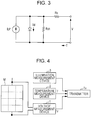
- Fig. 3 is a diagram illustrating an example in which a solar cell module is modeled in the form of an equivalent circuit.
- a current source, a diode, and a resistor are connected in parallel, and another resistor is connected in series to the parallel connection.
- the current source corresponds to an electromotive force
- Iph represents a current source component.
- the sum total of resistances of a substrate, a light-receiving layer, and an electrode portion of a solar cell module is represented by a series resistance component Rs.
- the loss resistance of the solar cell module is represented by a parallel resistance component Rsh.
- the current source component Iph, the series resistance component Rs, the parallel resistance component Rsh, and the characteristic of the diode are calculated in advance.
- the characteristic of the diode can be modeled with a Shockley diode equation (equation (1)).
- I d I o exp qV d nkT ⁇ 1
- Io represents a reverse saturation current (A)
- n represents an ideal diode factor
- q represents an elementary charge (1.60217733x10 ⁇ (-19)(C))
- k represents a Boltzmann constant (1.3806504x10 ⁇ (-23)(JK-1))
- T represents a temperature (K).
- the unknown variables Io, n, Rs, and Rsh are constant regardless of environment. Accordingly, by preparing pieces of actual measurement data of the set of I, V, and T, the number of which is equal to or larger than that of unknowns, and solving simultaneous equations, these unknown variables can be determined.
- Iph is a variable dependent on an illumination level. For example, it is assumed that the variable Iph is linearly proportional to an illumination level. Simultaneous equations can be solved by preparing pieces of actual measurement data of the set of I, V, T, and an illumination level, the number of which is equal to or larger than that of unknowns.
- an illumination measurement device 3 is disposed, and a short circuit current obtained when the terminals of a solar cell module become shorted or an open circuit voltage obtained when the terminals of the solar cell module are opened, which is a parameter substantially proportional to an illumination level, is measured.
- a device for measuring an illumination level has to be disposed.
- MPP Maximum Power Point
- a maximum operating point voltage Vpm of a solar cell is substantially linearly proportional to an open voltage Voc in an environment in which an illumination level is relatively high.
- Vpm is approximately 80% of Voc.
- Iph I o exp qV pm cnkT ⁇ 1 + V pm cR sh
- equation (6) used to derive Ipm from Vpm and T can be obtained.
- I o exp qV pm cnkT ⁇ exp q V pm + R s I pm nkT + V pm cR sh ⁇ V pm + R s I pm R sh ⁇ I pm 0
- variables other than Ipm can be calculated in advance as described previously or can be determined with data from a transmitter. Accordingly, Ipm, which is only one unknown variable in equation (6), can be calculated with, for example, a Newton method. Alternatively, Ipm can be calculated by performing a Taylor expansion on an exponent and then solving a polynomial expression.
- FIG. 5 An example of a configuration on a transmission side will be described with reference to Fig. 5 .
- Two solar cell modules M1 and M2 are connected in series.
- a voltage output from the series connection of the solar cell modules M1 and M2 is supplied to a power conditioner PW.
- the power conditioner PW is used to convert a generated dc voltage into an ac voltage and supply generated power to a commercial power supply system.
- the power conditioner PW has the MPP function (the maximum operating point control function) in which control processing is performed to obtain the maximum operating point at which power becomes the maximum in a current-voltage characteristic of a solar cell.
- Voltage and temperature measurement units 10 1 and 10 2 are connected to the solar cell module M1 and M2, respectively. Since the voltage and temperature measurement units 10 1 and 10 2 have the same configuration, only the detailed configuration of the voltage and temperature measurement unit 10 1 is illustrated in Fig. 5 .
- a voltage output from the solar cell module M1 is supplied to a regulator 11, and is divided by resistors 12 and 13.
- the regulator 11 stabilizes the output of the solar cell module M1 and outputs a dc voltage +Vcc1. In a case where the output voltage of the solar cell module M1 is higher than the rated voltage of the regulator 11, the output voltage of the solar cell module M1 is divided and is then supplied to the regulator 11.
- a voltage at a point of connection between the resistors 12 and 13 is input into an overvoltage protection circuit (OVP in Fig. 5 ) 14.
- the overvoltage protection circuit 14 performs control processing so as to prevent the voltage at the point of connection between the resistors 12 and 13 from being equal to or higher than the input rated voltage of an A/D converter (ADC in Fig. 5 ) 15 at the subsequent stage.
- Voltage data V1 is obtained from the A/D converter 15.
- the output voltage of the regulator 11 is supplied to the series connection of a resistor 16 and a thermistor 17.
- the thermistor 17 is, for example, a negative temperature coefficient thermistor, and has a resistance value corresponding to the temperature of the solar cell module M1.
- a temperature detection element is preferably disposed so that it can measure the surface temperature of a solar cell module. An element other than a thermistor may be used as a temperature detection element.
- a plurality of temperature detection elements may be disposed for the solar cell module M1 at different positions, and more accurate temperature detection may be performed with the outputs of these temperature detection elements.
- a voltage at the point of connection between the resistor 16 and the thermistor 17 is supplied to an A/D converter 18.
- Temperature data T1 is obtained from the A/D converter 18.
- the regulator 11 also functions as a power source for the A/D converters 15 and 18, and the output voltage +Vcc1 of the regulator 11 is supplied to the A/D converters 15 and 18.
- An identifier (ID) storage unit 19 is disposed, and an ID ID1 of the solar cell module M1 is output from the ID storage unit 19.
- the voltage data V1, the temperature data T1, and the ID ID1 of the solar cell module M1 are supplied to a multiplexer 20.
- the voltage and temperature measurement unit 10 2 for the solar cell module M2 outputs voltage data V2, temperature data T2, an ID ID2, and a voltage +Vcc2. These pieces of data are supplied to the multiplexer 20.
- a power supply voltage +Vcc for the multiplexer 20 and the transmitter Tx is obtained from one of the voltages +Vcc1 and +Vcc2.
- the multiplexer 20 multiplexes (for example time-division multiplexes) pieces of data pertaining to the solar cell modules M1 and M2 and supplies the multiplexed data to the transmitter Tx.
- the transmitter Tx is a radio transmitter, and includes an antenna. The measurement of a voltage and a temperature is performed at predetermined intervals.
- a multiplexer Since a multiplexer is disposed, pieces of data pertaining to a plurality of solar cell modules are transmitted from a single transmitter. However, a transmitter may be disposed for each solar cell module. In a case where there is a long distance between solar cell modules, it is better to dispose a transmitter for each solar cell module for the sake of simple wiring.
- control unit for controlling the transmission side including a power generator is disposed.
- the control unit is, for example, a microcomputer, and controls each unit on the transmission side by executing a program.
- a process illustrated in Fig. 6 is performed for the transmission side, for example, the solar cell module M1 under the control of the control unit.
- the voltage and temperature measurement unit 10 1 measures the voltage and temperature of the solar cell module M1.
- step ST2 voltage data and temperature data which are results of the measurement are supplied to the multiplexer 20 along with the ID ID1.
- these pieces of data and the ID ID1 are multiplexed with the voltage data, temperature data, and ID2 of another module (the solar cell module M2) and are transmitted from the transmitter Tx.
- the pieces of data of the measured voltage and temperature are transmitted to the receiver Rx along with an ID.
- the receiver Rx receives a signal from the transmitter Tx, performs receiving processing upon the received signal, and supplies the processed data to a demultiplexer 30.
- the demultiplexer 30 demultiplexes the multiplexed data and outputs IDs and pieces of measurement data.
- the ID ID1 output from the demultiplexer 30 is supplied to an authentication unit 32 in a power calculation and state determination section 31 1 .
- the authentication unit 32 compares the received ID with the ID ID1 registered in advance and performs authentication on the basis of a result of the comparison. At that time, a more complex authentication method such as mutual authentication may be performed.
- the voltage data V1 and the temperature data T1 are supplied from the demultiplexer 30 to a power calculation unit 33.
- the power calculation unit 33 calculates the current Iph generated by the solar cell module M1 with equations (1) to (6) acquired from the above-described equivalent circuit model of the solar cell module, and obtains power information P1 about power generated by the solar cell module M1 with the calculated current and the voltage data.
- the power information P1 obtained by the power calculation unit 33 is supplied to a state determination unit 34.
- the state determination unit 34 determines whether the solar cell module M1 is in a good state on the basis of the power information P1.
- the state determination unit 34 determines the failure and deterioration of the power generation module Ml, and outputs a determination signal St1 (for example several bits of digital data).
- the state determination unit 34 may use one of or the combination of the following methods.
- the power information P1 and the determination signal St1 output from the power calculation and state determination section 31 1 are supplied to the display unit 40.
- the display unit 40 includes a display element such as a Liquid Crystal Display (LCD) and a display control unit.
- LCD Liquid Crystal Display
- the ID ID2, the voltage data V2, and the temperature data T2 output from the demultiplexer 30 are supplied to a power calculation and state determination section 31 2 .
- the power calculation and state determination section 31 2 has a configuration similar to that of the power calculation and state determination section 31 1 , and outputs power information P2 and a determination signal St2.
- the power information P2 and the determination signal St2 are supplied to the display unit 40.
- the display unit 40 displays power generated by each solar cell module and an information determination result of each solar cell module.
- the display unit 40 may further display total power generated by all solar cell modules.
- a user can know the current power generation state of each solar cell module by seeing the display unit 40.
- the amount of power and the state do not necessarily have to be displayed, and may be used for processing other than display processing and control processing. For example, with output power information, automatic tracking control may be performed so that the panel of each solar cell module points at the sun.
- a control unit for controlling the receiving side is disposed.
- the control unit is, for example, a microcomputer, and controls each unit on the receiving side by executing a program.
- the function of each power calculation and state determination section can be performed by software processing by a Micro Processing Unit (MPU) or a Digital Signal Processor (DSP).
- MPU Micro Processing Unit
- DSP Digital Signal Processor
- a process illustrated in Fig. 8 is performed on the receiving side under the control of the control unit.
- the receiver Rx receives data and outputs the received data to the demultiplexer 30.
- the demultiplexer 30 demultiplexes the data.
- a solar cell module is identified with the ID ID1 demultiplexed from the data.
- step ST16 the display unit 40 displays power information for each solar cell module.
- step ST17 the above-described state determination is performed with power information acquired from the calculation. For example, in a case where there is little generated power, it is determined that the solar cell module has failed. In a case where generated power is equal to or smaller than a predetermined value, the generated power is converted into the degree of deterioration and the degree of deterioration is displayed. The process ends.
- a process (represented by step ST20 in Fig. 8 ) similar to the process from steps ST13 to ST18 is performed on another solar cell module (for example the solar cell module M2).
- another solar cell module for example the solar cell module M2.
- Fig. 9 is a diagram illustrating a configuration on a transmission side according to the second embodiment of the present disclosure. Referring to Fig. 9 , the same reference numerals are used to identify parts already described with reference to Fig. 5 .
- a power calculation unit is disposed for each solar cell module on the transmission side.
- a power calculation unit 25 1 is disposed for the solar cell module M1 on the transmission side, and obtains the power information P1 of the solar cell module M1 by calculation like in the first embodiment.
- the power information P1 output from the power calculation unit 25 1 and the ID ID1 are supplied to the multiplexer 20.
- a power calculation unit 25 2 is disposed for the solar cell module M2.
- the power information P2 output from the power calculation unit 25 2 and the ID ID2 are supplied to the multiplexer 20.
- the multiplexer 20 multiplexes the pieces of power information P1 and P2 and the IDs ID1 and ID2, and supplies the multiplexed data to the transmitter Tx.
- the transmitter Tx transmits the multiplexed data.
- a receiving side can receive power information itself, and therefore include no power calculation unit. Other than this point, the receiving side has the same configuration as that illustrated in Fig. 7 .
- a power calculation unit is disposed on a receiving side.
- a power calculation unit is disposed on a transmission side.
- a power calculation unit is disposed at a position outside a receiving side and a transmission side.
- Fig. 10 is a diagram illustrating a schematic configuration according to the third embodiment.
- the voltage and temperature of a solar cell module M are measured by the voltage measurement device 1 and the temperature measurement device 2, respectively.
- the transmitter Tx transmits these pieces of data.
- a transceiver TRx1 transmits received data to a transceiver TRx2 disposed at another place (for example a server or a cloud computer).
- the transceiver TRx2 supplies received voltage data and received temperature data to a power calculation unit 26.
- the power calculation unit 26 obtains power information P of the solar cell module M by calculation like in the first embodiment.
- the obtained power information P is supplied to the transceiver TRx2 and is transmitted from the transceiver TRx2.
- the transceiver TRx1 receives the power information P from the transceiver TRx2, and displays the received power information P on the display unit 40.
- the power information P is also supplied to a state determination unit 34.
- the failure and deterioration of the solar cell module M are determined, and a result of the determination is supplied to the display unit 40.
- the following effects are obtained. Since power management can be performed for each solar cell module, the occurrence of a failure and a shadow and the amount of generated power in each of the cardinal points can be easily determined. Since the characteristic of each solar cell module, which causes a failure, can be determined, a solar power generation system can be easily subjected to maintenance. A small and low-cost apparatus including a small number of components can be attached to each solar cell module. Since no component is disposed on a power transmission path of each solar cell module, an apparatus seldom produces trouble.
Landscapes
- Engineering & Computer Science (AREA)
- Power Engineering (AREA)
- Physics & Mathematics (AREA)
- General Physics & Mathematics (AREA)
- Theoretical Computer Science (AREA)
- Databases & Information Systems (AREA)
- Mathematical Physics (AREA)
- Software Systems (AREA)
- General Engineering & Computer Science (AREA)
- Data Mining & Analysis (AREA)
- Photovoltaic Devices (AREA)
- Testing Of Individual Semiconductor Devices (AREA)
- Charge And Discharge Circuits For Batteries Or The Like (AREA)
- Control Of Eletrric Generators (AREA)
Claims (15)
- Energieerzeugungsvorrichtung, Folgendes umfassend:
eine Energieberechnungseinheit (33), die für Folgendes konfiguriert ist:Empfangen von Messwerten physikalischer Größen eines Energieerzeugungsmoduls (M), die Spannungsinformationen und Temperaturinformationen enthalten, von dem Energieerzeugungsmodul (M) undBerechnen von Energieerzeugungsinformationen, die einen Wert für die erzeugte Elektroenergie des Energieerzeugungsmoduls (M) beinhalten, auf der Basis der empfangenen Spannungs- und Temperaturinformationen, und dadurch gekennzeichnet, dassdas Energieerzeugungsmodul ein Solarzellen-Energieerzeugungsmodul (M) ist und die Energieerzeugungsinformationen durch Verwenden eines festgelegten Modells auf der Basis einer Shockley-Gleichung für eine Diode in einer Ersatzschaltung des Solarzellen-Energieerzeugungsmoduls (M) berechnet werden. - Energieerzeugungsvorrichtung nach Anspruch 1, ferner eine Zustandsbestimmungseinheit (34) umfassend, die dafür konfiguriert ist, auf der Basis der Energieerzeugungsinformationen einen Betriebszustand des Solarzellen-Energieerzeugungsmoduls (M) zu bestimmen.
- Energieerzeugungsvorrichtung nach Anspruch 2, wobei die Zustandsbestimmungseinheit (34) dafür konfiguriert ist, einen verschlechterten Zustand oder einen Ausfallzustand des Solarzellen-Energieerzeugungsmoduls (M) zu erkennen.
- Energieerzeugungsvorrichtung nach einem der Ansprüche 1 bis 3, ferner eine Ausgabeeinheit (40) umfassend, die dafür konfiguriert ist, die Energieerzeugungsinformationen auszugeben.
- Energieerzeugungsvorrichtung nach Anspruch 4, wobei die Ausgabeeinheit (40) eine Anzeigeeinheit ist, die dafür konfiguriert ist, die Energieerzeugungsinformationen anzuzeigen.
- Energieerzeugungsvorrichtung nach einem der Ansprüche 1 bis 5, ferner einen Sender (Tx) umfassend, der dafür konfiguriert ist, die Spannungsinformationen und die Temperaturinformationen zu senden, und einen Empfänger (Rx), der kommunikationsfähig mit dem Sender (Tx) gekoppelt und dafür konfiguriert ist, die vom Sender (Tx) gesendeten Spannungsinformationen und Temperaturinformationen zu empfangen.
- Energieerzeugungsvorrichtung nach Anspruch 6, wobei ein Kommunikationsweg zwischen dem Empfänger (Rx) und dem Sender (Tx) eine drahtlose Verbindung ist.
- Energieerzeugungsvorrichtung nach einem der Ansprüche 6 oder 7, ferner eine Spannungs- und Temperaturmesseinheit (101, 102) umfassend, die dafür konfiguriert ist, die Spannungsinformationen und die Temperaturinformationen von dem Solarzellen-Energieerzeugungsmodul (M) zu messen, und dafür konfiguriert ist, die Spannungsinformationen und die Temperaturinformationen an den Sender (Tx) zu übertragen.
- Energieerzeugungsvorrichtung nach Anspruch 8, wobei die Spannungs- und Temperaturmesseinheit (101, 102) Folgendes umfasst:einen Regler (11), der dafür konfiguriert ist, einen Spannungsausgang aus dem Solarzellen-Energieerzeugungsmodul (M) zu stabilisieren, undeinen ersten und einen zweiten Widerstand (12, 13), die mit dem Regler (11) verbunden und dafür konfiguriert sind, den Spannungsausgang aus dem Solarzellen-Energieerzeugungsmodul (M) zu teilen, wenn der Spannungsausgang aus dem Solarzellen-Energieerzeugungsmodul (M) höher als eine Nennspannung des Reglers (11) ist.
- Energieerzeugungsvorrichtung nach Anspruch 1, ferner Folgendes umfassend:einen Sender (Tx),einen Empfänger (Rx), der kommunikationsfähig mit dem Sender (Tx) verbunden ist, undeine Zustandsbestimmungseinheit (34), die dafür konfiguriert ist, auf der Basis der vom Empfänger (Rx) empfangenen Energieerzeugungsinformationen einen Betriebszustand des Solarzellen-Energieerzeugungsmoduls (M) zu bestimmen.
- Energieerzeugungsvorrichtung nach Anspruch 10, wobei die Energieberechnungseinheit (33) an einer Sendeseite der Energieerzeugungsvorrichtung positioniert ist und die Zustandsbestimmungseinheit (34) an einer Empfangsseite der Energieerzeugungsvorrichtung positioniert ist.
- Verfahren zum Bestimmen eines Betriebszustandes einer Energieerzeugungsvorrichtung, wobei das Verfahren Folgendes umfasst:Empfangen von Messwerten physikalischer Größen eines Energieerzeugungsmoduls (M), die Spannungsinformationen und Temperaturinformationen enthalten, von dem Energieerzeugungsmodul (M) und Berechnen von Energieerzeugungsinformationen, die einen Wert für die erzeugte Elektroenergie des Energieerzeugungsmoduls (M) beinhalten, undBestimmen des Betriebszustandes des Energieerzeugungsmoduls (M) auf der Basis der Energieerzeugungsinformationen, und dadurch gekennzeichnet, dassdas Energieerzeugungsmodul ein Solarzellen-Energieerzeugungsmodul (M) ist und die Energieerzeugungsinformationen durch Verwenden eines festgelegten Modells auf der Basis einer Shockley-Gleichung für eine Diode in einer Ersatzschaltung des Solarzellen-Energieerzeugungsmoduls (M) berechnet werden.
- Verfahren nach Anspruch 12, ferner das Bestimmen eines Betriebszustandes des Solarzellen-Energieerzeugungsmodul (M) auf der Basis der Energieerzeugungsinformationen umfassend.
- Verfahren nach Anspruch 13, ferner das Bestimmen umfassend, ob der Betriebszustand des Solarzellen-Energieerzeugungsmoduls (M) ein verschlechterter Zustand oder ein Ausfallzustand ist.
- Verfahren nach einem der Ansprüche 12 bis 14, ferner das Ausgeben der Energieerzeugungsinformationen umfassend.
Applications Claiming Priority (1)
| Application Number | Priority Date | Filing Date | Title |
|---|---|---|---|
| JP2011260771A JP6003048B2 (ja) | 2011-11-29 | 2011-11-29 | 発電装置 |
Publications (3)
| Publication Number | Publication Date |
|---|---|
| EP2600480A2 EP2600480A2 (de) | 2013-06-05 |
| EP2600480A3 EP2600480A3 (de) | 2016-03-23 |
| EP2600480B1 true EP2600480B1 (de) | 2019-09-18 |
Family
ID=47598543
Family Applications (1)
| Application Number | Title | Priority Date | Filing Date |
|---|---|---|---|
| EP12007381.2A Not-in-force EP2600480B1 (de) | 2011-11-29 | 2012-10-26 | Stromerzeugungsvorrichtung |
Country Status (5)
| Country | Link |
|---|---|
| US (1) | US9599646B2 (de) |
| EP (1) | EP2600480B1 (de) |
| JP (1) | JP6003048B2 (de) |
| KR (2) | KR20130060126A (de) |
| CN (1) | CN103135045B (de) |
Families Citing this family (14)
| Publication number | Priority date | Publication date | Assignee | Title |
|---|---|---|---|---|
| US20130009483A1 (en) * | 2011-05-31 | 2013-01-10 | Kawate Keith W | Power generator module connectivity control |
| JP5814775B2 (ja) * | 2011-12-22 | 2015-11-17 | 株式会社日立製作所 | 太陽電池の特性演算方法 |
| JP5671488B2 (ja) | 2012-03-14 | 2015-02-18 | 東京エレクトロン株式会社 | 太陽電池モジュールの効能監視システム及びその監視方法 |
| WO2014069363A1 (ja) * | 2012-11-02 | 2014-05-08 | ローム株式会社 | チップコンデンサ、回路アセンブリ、および電子機器 |
| US20150212561A1 (en) * | 2013-07-30 | 2015-07-30 | New Concepts Development Corp. | Apparatus and Method for Powering Electronic Devices by a Plurality of Power Sources |
| US9520722B2 (en) | 2013-11-15 | 2016-12-13 | Epsel Co., Ltd. | Solar power generation management apparatus |
| JP6354946B2 (ja) * | 2014-07-18 | 2018-07-11 | Jfeエンジニアリング株式会社 | 太陽光発電システムの異常診断方法 |
| DE102016004362A1 (de) * | 2016-04-09 | 2017-10-12 | Audi Ag | Kraftfahrzeug und Solarwandlereinrichtung |
| US11874449B2 (en) | 2016-04-12 | 2024-01-16 | Jonathan Jacques | Pyramidal wall sections |
| CN108064361B (zh) * | 2016-08-18 | 2021-06-01 | 苏州聚晟太阳能科技股份有限公司 | 智能化跟踪系统及方法 |
| CN109783852A (zh) * | 2018-12-10 | 2019-05-21 | 北京汉能光伏投资有限公司 | 仿真装置及其仿真方法、计算机可读存储介质 |
| JP7299749B2 (ja) * | 2019-05-10 | 2023-06-28 | 東北電力株式会社 | 太陽光発電出力予測装置、太陽光発電出力予測方法、及びプログラム |
| WO2022010865A1 (en) * | 2020-07-06 | 2022-01-13 | Jonathan Jacques | Pyramidal wall sections |
| CA3221623A1 (en) * | 2021-06-14 | 2022-12-22 | Martin Guthrie | Circuit topologies for wide dynamic range current measurement |
Family Cites Families (36)
| Publication number | Priority date | Publication date | Assignee | Title |
|---|---|---|---|---|
| JP3392506B2 (ja) * | 1994-02-24 | 2003-03-31 | 株式会社東芝 | 太陽光発電模擬装置 |
| JPH07235685A (ja) * | 1994-02-25 | 1995-09-05 | Nissin Electric Co Ltd | 太陽光発電パネルの耐圧試験方法 |
| JP3403854B2 (ja) * | 1995-04-07 | 2003-05-06 | 淳 伊賀 | 太陽電池テスター |
| JPH09102622A (ja) | 1995-10-03 | 1997-04-15 | Nissin Electric Co Ltd | 太陽光発電システムの太陽電池モジュールの故障検出装置 |
| CN1161678C (zh) * | 1998-03-30 | 2004-08-11 | 三洋电机株式会社 | 太阳能发电装置 |
| US6111767A (en) * | 1998-06-22 | 2000-08-29 | Heliotronics, Inc. | Inverter integrated instrumentation having a current-voltage curve tracer |
| EP1611448A1 (de) * | 2003-04-04 | 2006-01-04 | BP Corporation North America Inc. | Leistungsfähigkeitsüberwachungsvorrichtung für eine photovoltaische versorgung |
| US7510640B2 (en) * | 2004-02-18 | 2009-03-31 | General Motors Corporation | Method and apparatus for hydrogen generation |
| WO2007125867A1 (ja) * | 2006-04-24 | 2007-11-08 | Sharp Kabushiki Kaisha | 太陽光発電システムおよび太陽光発電システム制御方法 |
| JP5162737B2 (ja) * | 2006-05-17 | 2013-03-13 | 英弘精機株式会社 | 太陽電池の特性評価装置 |
| JP2008046751A (ja) * | 2006-08-11 | 2008-02-28 | Toyota Motor Corp | 太陽光発電システム、車両、太陽光発電システムの制御方法、およびその制御方法をコンピュータに実行させるためのプログラムを記録したコンピュータ読取可能な記録媒体 |
| JP2008141918A (ja) * | 2006-12-05 | 2008-06-19 | Nippon Telegr & Teleph Corp <Ntt> | 太陽光発電システム評価装置、方法、およびプログラム |
| US8473250B2 (en) * | 2006-12-06 | 2013-06-25 | Solaredge, Ltd. | Monitoring of distributed power harvesting systems using DC power sources |
| US7772716B2 (en) * | 2007-03-27 | 2010-08-10 | Newdoll Enterprises Llc | Distributed maximum power point tracking system, structure and process |
| US20080257397A1 (en) * | 2007-04-17 | 2008-10-23 | John Stanley Glaser | System, method, and apparatus for extracting power from a photovoltaic source of electrical energy |
| US20080306700A1 (en) * | 2007-06-07 | 2008-12-11 | Ekla-Tek L.L.C | Photvoltaic solar array health monitor |
| KR100933894B1 (ko) * | 2007-11-13 | 2009-12-28 | 한국전기연구원 | 태양전지 특성곡선 모의 시스템 및 그 방법 |
| KR20110014200A (ko) * | 2008-05-14 | 2011-02-10 | 내셔널 세미콘덕터 코포레이션 | 지능형 인터버들의 어레이를 위한 시스템 및 방법 |
| US8446046B2 (en) * | 2008-10-03 | 2013-05-21 | Access Business Group International Llc | Power system |
| JP2010123880A (ja) * | 2008-11-21 | 2010-06-03 | Ntt Facilities Inc | 故障判定システム、故障判定方法、コンピュータプログラム |
| JP2010186795A (ja) * | 2009-02-10 | 2010-08-26 | Sony Corp | 光電池装置、および故障判定方法 |
| CN201383693Y (zh) * | 2009-04-08 | 2010-01-13 | 北京远方动力可再生能源科技发展有限公司 | 太阳能充放电控制器 |
| JP5597937B2 (ja) * | 2009-05-26 | 2014-10-01 | 株式会社日立製作所 | 太陽光発電システム |
| JP2010287608A (ja) | 2009-06-09 | 2010-12-24 | Kowa Denki Sangyo Kk | 太陽光発電装置の劣化検出装置、太陽光発電装置の劣化検出システム、太陽光発電装置の劣化検出方法 |
| US20100321148A1 (en) * | 2009-06-18 | 2010-12-23 | Peter Gevorkian | Wireless intelligent solar power reader (wispr) structure and process |
| CA2768459A1 (en) * | 2009-07-14 | 2011-01-20 | Enphase Energy, Inc. | Method and apparatus for identifying redeployed distributed generator components |
| JP5581965B2 (ja) * | 2010-01-19 | 2014-09-03 | オムロン株式会社 | Mppt制御器、太陽電池制御装置、太陽光発電システム、mppt制御プログラム、およびmppt制御器の制御方法 |
| JP5569044B2 (ja) * | 2010-03-03 | 2014-08-13 | ソニー株式会社 | 電力制御装置、電力制御方法、および給電システム |
| US20110222327A1 (en) * | 2010-03-11 | 2011-09-15 | Christopher Thompson | Photovoltaic Inverter Power System |
| US20110224839A1 (en) * | 2010-03-11 | 2011-09-15 | Christopher Thompson | Power Point Tracking |
| US20120053867A1 (en) * | 2010-08-24 | 2012-03-01 | Atonometrics, Inc. | System and methods for high-precision string-level measurement of photovoltaic array performance |
| KR101026139B1 (ko) * | 2010-09-01 | 2011-04-05 | (주)케이디티 | 태양광 발전 시스템에 있어서 pv 모듈의 개별적인 진단이 가능한 pv 진단 장치 |
| CN201974514U (zh) * | 2010-11-02 | 2011-09-14 | 中山大学 | 基于tms320f2812的光伏阵列测试装置 |
| US8531164B2 (en) * | 2011-04-04 | 2013-09-10 | Advanced Analogic Technologies Incorporated | Operational transconductance amplifier feedback mechanism for fixed feedback voltage regulators |
| US20120310427A1 (en) * | 2011-05-31 | 2012-12-06 | Williams B Jeffery | Automatic Monitoring and Adjustment of a Solar Panel Array |
| KR101083818B1 (ko) * | 2011-08-10 | 2011-11-18 | (주) 경원 | 태양 전지 모듈 모니터링 시스템 |
-
2011
- 2011-11-29 JP JP2011260771A patent/JP6003048B2/ja not_active Expired - Fee Related
-
2012
- 2012-10-26 EP EP12007381.2A patent/EP2600480B1/de not_active Not-in-force
- 2012-11-21 KR KR1020120132405A patent/KR20130060126A/ko not_active Ceased
- 2012-11-21 US US13/683,478 patent/US9599646B2/en not_active Expired - Fee Related
- 2012-11-22 CN CN201210479420.3A patent/CN103135045B/zh not_active Expired - Fee Related
-
2020
- 2020-01-08 KR KR1020200002631A patent/KR102175692B1/ko not_active Expired - Fee Related
Non-Patent Citations (1)
| Title |
|---|
| None * |
Also Published As
| Publication number | Publication date |
|---|---|
| KR102175692B1 (ko) | 2020-11-06 |
| EP2600480A3 (de) | 2016-03-23 |
| CN103135045B (zh) | 2017-05-24 |
| KR20130060126A (ko) | 2013-06-07 |
| CN103135045A (zh) | 2013-06-05 |
| US9599646B2 (en) | 2017-03-21 |
| KR20200011036A (ko) | 2020-01-31 |
| JP2013113739A (ja) | 2013-06-10 |
| US20130138259A1 (en) | 2013-05-30 |
| EP2600480A2 (de) | 2013-06-05 |
| JP6003048B2 (ja) | 2016-10-05 |
Similar Documents
| Publication | Publication Date | Title |
|---|---|---|
| US9599646B2 (en) | Power generation apparatus | |
| US10312858B2 (en) | Solar power generation system and failure diagnosis method therefor | |
| US20210313928A1 (en) | Method and apparatus for determining key performance photovoltaic characteristics using sensors from module-level power electronics | |
| US6111767A (en) | Inverter integrated instrumentation having a current-voltage curve tracer | |
| JP6209412B2 (ja) | 太陽光発電システムの故障診断システム及び故障診断方法 | |
| JP5617695B2 (ja) | 太陽光発電ユニットの診断装置 | |
| KR100909978B1 (ko) | 태양광발전시스템의 출력 보정 및 성능 검증 장치 및 그 방법 | |
| JP6758273B2 (ja) | 太陽電池診断装置および太陽電池診断方法 | |
| KR101669340B1 (ko) | 복수 태양광 모듈을 평가하기 위한 다채널 모니터링 시스템 | |
| CN107276529A (zh) | 太阳能板发电异常测试方法及其系统 | |
| JP6806325B2 (ja) | 太陽光発電システム評価装置、評価方法、及び、評価装置用プログラム | |
| KR20180069236A (ko) | 태양광 발전기 고장 진단용 통합 모니터링 시스템 | |
| JP2014022686A (ja) | 異常検出装置、異常検出方法および発電システム | |
| Andò et al. | SENTINELLA: A WSN for a smart monitoring of PV systems at module level | |
| JP2014232770A (ja) | 太陽光発電システム装置 | |
| JP2020028192A (ja) | 太陽光発電装置、診断装置および太陽電池ストリングの診断方法 | |
| JP5800069B2 (ja) | 太陽光発電ユニットの診断装置、診断方法、及び太陽光発電システム | |
| CN215492129U (zh) | 一种温度检测电路及测试工装 | |
| JP6759081B2 (ja) | 太陽電池特性の把握方法および太陽光発電制御システム | |
| KR20130049064A (ko) | 태양광 시스템의 설계손실 측정장치 및 방법 | |
| JP6408280B2 (ja) | 太陽電池の異常検出方法、及び電力管理装置 | |
| JP5881759B2 (ja) | 太陽光発電システムにおける性能検査装置及びプログラム | |
| WO2016170558A1 (ja) | 診断装置、診断システムおよび診断方法 | |
| JP6300148B2 (ja) | 太陽光発電装置の管理装置 | |
| US20170149380A1 (en) | Embedded photovoltaic monitoring device, system and method |
Legal Events
| Date | Code | Title | Description |
|---|---|---|---|
| PUAI | Public reference made under article 153(3) epc to a published international application that has entered the european phase |
Free format text: ORIGINAL CODE: 0009012 |
|
| 17P | Request for examination filed |
Effective date: 20121026 |
|
| AK | Designated contracting states |
Kind code of ref document: A2 Designated state(s): AL AT BE BG CH CY CZ DE DK EE ES FI FR GB GR HR HU IE IS IT LI LT LU LV MC MK MT NL NO PL PT RO RS SE SI SK SM TR |
|
| AX | Request for extension of the european patent |
Extension state: BA ME |
|
| PUAL | Search report despatched |
Free format text: ORIGINAL CODE: 0009013 |
|
| AK | Designated contracting states |
Kind code of ref document: A3 Designated state(s): AL AT BE BG CH CY CZ DE DK EE ES FI FR GB GR HR HU IE IS IT LI LT LU LV MC MK MT NL NO PL PT RO RS SE SI SK SM TR |
|
| AX | Request for extension of the european patent |
Extension state: BA ME |
|
| RIC1 | Information provided on ipc code assigned before grant |
Ipc: H02J 3/38 20060101AFI20160216BHEP Ipc: H01L 31/02 20060101ALI20160216BHEP Ipc: H02M 7/00 20060101ALI20160216BHEP Ipc: H01L 31/042 20060101ALI20160216BHEP |
|
| STAA | Information on the status of an ep patent application or granted ep patent |
Free format text: STATUS: EXAMINATION IS IN PROGRESS |
|
| 17Q | First examination report despatched |
Effective date: 20170324 |
|
| GRAP | Despatch of communication of intention to grant a patent |
Free format text: ORIGINAL CODE: EPIDOSNIGR1 |
|
| STAA | Information on the status of an ep patent application or granted ep patent |
Free format text: STATUS: GRANT OF PATENT IS INTENDED |
|
| INTG | Intention to grant announced |
Effective date: 20190424 |
|
| GRAS | Grant fee paid |
Free format text: ORIGINAL CODE: EPIDOSNIGR3 |
|
| GRAA | (expected) grant |
Free format text: ORIGINAL CODE: 0009210 |
|
| STAA | Information on the status of an ep patent application or granted ep patent |
Free format text: STATUS: THE PATENT HAS BEEN GRANTED |
|
| AK | Designated contracting states |
Kind code of ref document: B1 Designated state(s): AL AT BE BG CH CY CZ DE DK EE ES FI FR GB GR HR HU IE IS IT LI LT LU LV MC MK MT NL NO PL PT RO RS SE SI SK SM TR |
|
| REG | Reference to a national code |
Ref country code: GB Ref legal event code: FG4D |
|
| REG | Reference to a national code |
Ref country code: CH Ref legal event code: EP |
|
| REG | Reference to a national code |
Ref country code: AT Ref legal event code: REF Ref document number: 1182443 Country of ref document: AT Kind code of ref document: T Effective date: 20191015 |
|
| REG | Reference to a national code |
Ref country code: IE Ref legal event code: FG4D |
|
| REG | Reference to a national code |
Ref country code: DE Ref legal event code: R096 Ref document number: 602012064036 Country of ref document: DE |
|
| REG | Reference to a national code |
Ref country code: NL Ref legal event code: MP Effective date: 20190918 |
|
| PG25 | Lapsed in a contracting state [announced via postgrant information from national office to epo] |
Ref country code: FI Free format text: LAPSE BECAUSE OF FAILURE TO SUBMIT A TRANSLATION OF THE DESCRIPTION OR TO PAY THE FEE WITHIN THE PRESCRIBED TIME-LIMIT Effective date: 20190918 Ref country code: LT Free format text: LAPSE BECAUSE OF FAILURE TO SUBMIT A TRANSLATION OF THE DESCRIPTION OR TO PAY THE FEE WITHIN THE PRESCRIBED TIME-LIMIT Effective date: 20190918 Ref country code: HR Free format text: LAPSE BECAUSE OF FAILURE TO SUBMIT A TRANSLATION OF THE DESCRIPTION OR TO PAY THE FEE WITHIN THE PRESCRIBED TIME-LIMIT Effective date: 20190918 Ref country code: BG Free format text: LAPSE BECAUSE OF FAILURE TO SUBMIT A TRANSLATION OF THE DESCRIPTION OR TO PAY THE FEE WITHIN THE PRESCRIBED TIME-LIMIT Effective date: 20191218 Ref country code: SE Free format text: LAPSE BECAUSE OF FAILURE TO SUBMIT A TRANSLATION OF THE DESCRIPTION OR TO PAY THE FEE WITHIN THE PRESCRIBED TIME-LIMIT Effective date: 20190918 Ref country code: NO Free format text: LAPSE BECAUSE OF FAILURE TO SUBMIT A TRANSLATION OF THE DESCRIPTION OR TO PAY THE FEE WITHIN THE PRESCRIBED TIME-LIMIT Effective date: 20191218 |
|
| REG | Reference to a national code |
Ref country code: LT Ref legal event code: MG4D |
|
| PG25 | Lapsed in a contracting state [announced via postgrant information from national office to epo] |
Ref country code: GR Free format text: LAPSE BECAUSE OF FAILURE TO SUBMIT A TRANSLATION OF THE DESCRIPTION OR TO PAY THE FEE WITHIN THE PRESCRIBED TIME-LIMIT Effective date: 20191219 Ref country code: LV Free format text: LAPSE BECAUSE OF FAILURE TO SUBMIT A TRANSLATION OF THE DESCRIPTION OR TO PAY THE FEE WITHIN THE PRESCRIBED TIME-LIMIT Effective date: 20190918 Ref country code: RS Free format text: LAPSE BECAUSE OF FAILURE TO SUBMIT A TRANSLATION OF THE DESCRIPTION OR TO PAY THE FEE WITHIN THE PRESCRIBED TIME-LIMIT Effective date: 20190918 Ref country code: AL Free format text: LAPSE BECAUSE OF FAILURE TO SUBMIT A TRANSLATION OF THE DESCRIPTION OR TO PAY THE FEE WITHIN THE PRESCRIBED TIME-LIMIT Effective date: 20190918 |
|
| REG | Reference to a national code |
Ref country code: AT Ref legal event code: MK05 Ref document number: 1182443 Country of ref document: AT Kind code of ref document: T Effective date: 20190918 |
|
| PG25 | Lapsed in a contracting state [announced via postgrant information from national office to epo] |
Ref country code: PT Free format text: LAPSE BECAUSE OF FAILURE TO SUBMIT A TRANSLATION OF THE DESCRIPTION OR TO PAY THE FEE WITHIN THE PRESCRIBED TIME-LIMIT Effective date: 20200120 Ref country code: AT Free format text: LAPSE BECAUSE OF FAILURE TO SUBMIT A TRANSLATION OF THE DESCRIPTION OR TO PAY THE FEE WITHIN THE PRESCRIBED TIME-LIMIT Effective date: 20190918 Ref country code: IT Free format text: LAPSE BECAUSE OF FAILURE TO SUBMIT A TRANSLATION OF THE DESCRIPTION OR TO PAY THE FEE WITHIN THE PRESCRIBED TIME-LIMIT Effective date: 20190918 Ref country code: RO Free format text: LAPSE BECAUSE OF FAILURE TO SUBMIT A TRANSLATION OF THE DESCRIPTION OR TO PAY THE FEE WITHIN THE PRESCRIBED TIME-LIMIT Effective date: 20190918 Ref country code: NL Free format text: LAPSE BECAUSE OF FAILURE TO SUBMIT A TRANSLATION OF THE DESCRIPTION OR TO PAY THE FEE WITHIN THE PRESCRIBED TIME-LIMIT Effective date: 20190918 Ref country code: EE Free format text: LAPSE BECAUSE OF FAILURE TO SUBMIT A TRANSLATION OF THE DESCRIPTION OR TO PAY THE FEE WITHIN THE PRESCRIBED TIME-LIMIT Effective date: 20190918 Ref country code: ES Free format text: LAPSE BECAUSE OF FAILURE TO SUBMIT A TRANSLATION OF THE DESCRIPTION OR TO PAY THE FEE WITHIN THE PRESCRIBED TIME-LIMIT Effective date: 20190918 Ref country code: PL Free format text: LAPSE BECAUSE OF FAILURE TO SUBMIT A TRANSLATION OF THE DESCRIPTION OR TO PAY THE FEE WITHIN THE PRESCRIBED TIME-LIMIT Effective date: 20190918 |
|
| PG25 | Lapsed in a contracting state [announced via postgrant information from national office to epo] |
Ref country code: SK Free format text: LAPSE BECAUSE OF FAILURE TO SUBMIT A TRANSLATION OF THE DESCRIPTION OR TO PAY THE FEE WITHIN THE PRESCRIBED TIME-LIMIT Effective date: 20190918 Ref country code: SM Free format text: LAPSE BECAUSE OF FAILURE TO SUBMIT A TRANSLATION OF THE DESCRIPTION OR TO PAY THE FEE WITHIN THE PRESCRIBED TIME-LIMIT Effective date: 20190918 Ref country code: IS Free format text: LAPSE BECAUSE OF FAILURE TO SUBMIT A TRANSLATION OF THE DESCRIPTION OR TO PAY THE FEE WITHIN THE PRESCRIBED TIME-LIMIT Effective date: 20200224 Ref country code: CZ Free format text: LAPSE BECAUSE OF FAILURE TO SUBMIT A TRANSLATION OF THE DESCRIPTION OR TO PAY THE FEE WITHIN THE PRESCRIBED TIME-LIMIT Effective date: 20190918 |
|
| REG | Reference to a national code |
Ref country code: CH Ref legal event code: PL |
|
| REG | Reference to a national code |
Ref country code: DE Ref legal event code: R097 Ref document number: 602012064036 Country of ref document: DE |
|
| PLBE | No opposition filed within time limit |
Free format text: ORIGINAL CODE: 0009261 |
|
| STAA | Information on the status of an ep patent application or granted ep patent |
Free format text: STATUS: NO OPPOSITION FILED WITHIN TIME LIMIT |
|
| PG2D | Information on lapse in contracting state deleted |
Ref country code: IS |
|
| PG25 | Lapsed in a contracting state [announced via postgrant information from national office to epo] |
Ref country code: LU Free format text: LAPSE BECAUSE OF NON-PAYMENT OF DUE FEES Effective date: 20191026 Ref country code: CH Free format text: LAPSE BECAUSE OF NON-PAYMENT OF DUE FEES Effective date: 20191031 Ref country code: LI Free format text: LAPSE BECAUSE OF NON-PAYMENT OF DUE FEES Effective date: 20191031 Ref country code: DK Free format text: LAPSE BECAUSE OF FAILURE TO SUBMIT A TRANSLATION OF THE DESCRIPTION OR TO PAY THE FEE WITHIN THE PRESCRIBED TIME-LIMIT Effective date: 20190918 Ref country code: IS Free format text: LAPSE BECAUSE OF FAILURE TO SUBMIT A TRANSLATION OF THE DESCRIPTION OR TO PAY THE FEE WITHIN THE PRESCRIBED TIME-LIMIT Effective date: 20200119 |
|
| REG | Reference to a national code |
Ref country code: BE Ref legal event code: MM Effective date: 20191031 |
|
| 26N | No opposition filed |
Effective date: 20200619 |
|
| PG25 | Lapsed in a contracting state [announced via postgrant information from national office to epo] |
Ref country code: MC Free format text: LAPSE BECAUSE OF FAILURE TO SUBMIT A TRANSLATION OF THE DESCRIPTION OR TO PAY THE FEE WITHIN THE PRESCRIBED TIME-LIMIT Effective date: 20190918 Ref country code: SI Free format text: LAPSE BECAUSE OF FAILURE TO SUBMIT A TRANSLATION OF THE DESCRIPTION OR TO PAY THE FEE WITHIN THE PRESCRIBED TIME-LIMIT Effective date: 20190918 Ref country code: BE Free format text: LAPSE BECAUSE OF NON-PAYMENT OF DUE FEES Effective date: 20191031 |
|
| GBPC | Gb: european patent ceased through non-payment of renewal fee |
Effective date: 20191218 |
|
| PG25 | Lapsed in a contracting state [announced via postgrant information from national office to epo] |
Ref country code: FR Free format text: LAPSE BECAUSE OF NON-PAYMENT OF DUE FEES Effective date: 20191118 Ref country code: IE Free format text: LAPSE BECAUSE OF NON-PAYMENT OF DUE FEES Effective date: 20191026 Ref country code: GB Free format text: LAPSE BECAUSE OF NON-PAYMENT OF DUE FEES Effective date: 20191218 |
|
| PG25 | Lapsed in a contracting state [announced via postgrant information from national office to epo] |
Ref country code: CY Free format text: LAPSE BECAUSE OF FAILURE TO SUBMIT A TRANSLATION OF THE DESCRIPTION OR TO PAY THE FEE WITHIN THE PRESCRIBED TIME-LIMIT Effective date: 20190918 |
|
| PG25 | Lapsed in a contracting state [announced via postgrant information from national office to epo] |
Ref country code: MT Free format text: LAPSE BECAUSE OF FAILURE TO SUBMIT A TRANSLATION OF THE DESCRIPTION OR TO PAY THE FEE WITHIN THE PRESCRIBED TIME-LIMIT Effective date: 20190918 Ref country code: HU Free format text: LAPSE BECAUSE OF FAILURE TO SUBMIT A TRANSLATION OF THE DESCRIPTION OR TO PAY THE FEE WITHIN THE PRESCRIBED TIME-LIMIT; INVALID AB INITIO Effective date: 20121026 |
|
| PG25 | Lapsed in a contracting state [announced via postgrant information from national office to epo] |
Ref country code: TR Free format text: LAPSE BECAUSE OF FAILURE TO SUBMIT A TRANSLATION OF THE DESCRIPTION OR TO PAY THE FEE WITHIN THE PRESCRIBED TIME-LIMIT Effective date: 20190918 |
|
| PG25 | Lapsed in a contracting state [announced via postgrant information from national office to epo] |
Ref country code: MK Free format text: LAPSE BECAUSE OF FAILURE TO SUBMIT A TRANSLATION OF THE DESCRIPTION OR TO PAY THE FEE WITHIN THE PRESCRIBED TIME-LIMIT Effective date: 20190918 |
|
| PGFP | Annual fee paid to national office [announced via postgrant information from national office to epo] |
Ref country code: DE Payment date: 20220616 Year of fee payment: 11 |
|
| P01 | Opt-out of the competence of the unified patent court (upc) registered |
Effective date: 20230527 |
|
| REG | Reference to a national code |
Ref country code: DE Ref legal event code: R119 Ref document number: 602012064036 Country of ref document: DE |
|
| PG25 | Lapsed in a contracting state [announced via postgrant information from national office to epo] |
Ref country code: DE Free format text: LAPSE BECAUSE OF NON-PAYMENT OF DUE FEES Effective date: 20240501 |