EP2600564A2 - System und Verfahren für weitreichende Leistung über Ethernet unter Verwendung von integrierten Boost-Repeatern - Google Patents
System und Verfahren für weitreichende Leistung über Ethernet unter Verwendung von integrierten Boost-Repeatern Download PDFInfo
- Publication number
- EP2600564A2 EP2600564A2 EP12005846.6A EP12005846A EP2600564A2 EP 2600564 A2 EP2600564 A2 EP 2600564A2 EP 12005846 A EP12005846 A EP 12005846A EP 2600564 A2 EP2600564 A2 EP 2600564A2
- Authority
- EP
- European Patent Office
- Prior art keywords
- power
- voltage level
- cable
- over ethernet
- powered device
- Prior art date
- Legal status (The legal status is an assumption and is not a legal conclusion. Google has not performed a legal analysis and makes no representation as to the accuracy of the status listed.)
- Withdrawn
Links
- 238000000034 method Methods 0.000 title claims abstract description 13
- 238000011144 upstream manufacturing Methods 0.000 claims description 6
- 238000012358 sourcing Methods 0.000 claims description 5
- 230000005540 biological transmission Effects 0.000 description 3
- 230000001419 dependent effect Effects 0.000 description 3
- 239000004606 Fillers/Extenders Substances 0.000 description 2
- 230000007423 decrease Effects 0.000 description 1
- 238000010586 diagram Methods 0.000 description 1
- 239000000284 extract Substances 0.000 description 1
- 238000012986 modification Methods 0.000 description 1
- 230000004048 modification Effects 0.000 description 1
Images


Classifications
-
- H—ELECTRICITY
- H04—ELECTRIC COMMUNICATION TECHNIQUE
- H04L—TRANSMISSION OF DIGITAL INFORMATION, e.g. TELEGRAPHIC COMMUNICATION
- H04L25/00—Baseband systems
- H04L25/38—Synchronous or start-stop systems, e.g. for Baudot code
-
- H—ELECTRICITY
- H04—ELECTRIC COMMUNICATION TECHNIQUE
- H04L—TRANSMISSION OF DIGITAL INFORMATION, e.g. TELEGRAPHIC COMMUNICATION
- H04L12/00—Data switching networks
- H04L12/02—Details
- H04L12/10—Current supply arrangements
-
- H—ELECTRICITY
- H04—ELECTRIC COMMUNICATION TECHNIQUE
- H04L—TRANSMISSION OF DIGITAL INFORMATION, e.g. TELEGRAPHIC COMMUNICATION
- H04L12/00—Data switching networks
- H04L12/28—Data switching networks characterised by path configuration, e.g. LAN [Local Area Networks] or WAN [Wide Area Networks]
- H04L12/46—Interconnection of networks
- H04L12/4604—LAN interconnection over a backbone network, e.g. Internet, Frame Relay
- H04L12/462—LAN interconnection over a bridge based backbone
- H04L12/4625—Single bridge functionality, e.g. connection of two networks over a single bridge
Definitions
- the present invention relates generally to network powering systems and methods and, more particularly, to a system and method for long range power over Ethernet (PoE) using integrated boost repeaters.
- PoE power over Ethernet
- PoE provides a framework for delivery of power from power sourcing equipment (PSE) to a powered device (PD) over Ethernet cabling.
- PSE power sourcing equipment
- PD powered device
- VoIP voice over IP
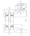
- FIG. 1 illustrates an example of a conventional power over Ethernet (PoE) system.
- the PoE system includes PSE 120 that transmits power to powered device (PD) 140 over two wire pairs.
- Power delivered by PSE 120 to PD 140 is provided through the application of a voltage across the center taps of a first transformer that is coupled to a transmit (TX) wire pair and a second transformer that is coupled to a receive (RX) wire pair carried within an Ethernet cable.
- TX transmit
- RX receive
- PoE module 142 includes the electronics that would enable PD 140 to communicate with PSE 120 in accordance with a PoE specification such as IEEE 802.3af (PoE), 802.3at (PoE Plus), legacy PoE transmission, or any other type of PoE transmission.
- PD 140 also includes controller 144 (e.g., pulse width modulation DC:DC controller) that controls power FET 146, which in turn provides constant power to load 150.
- controller 144 e.g., pulse width modulation DC:DC controller
- PoE was defined for Ethernet applications that had cable lengths of a 100 meters or less.
- Long range Ethernet i.e., cable lengths greater than 100 meters
- a system and/or method for long range power over Ethernet using integrated boost repeaters substantially as shown in and/or described in connection with at least one of the figures, as set forth more completely in the claims.
- a power over Ethernet repeater inserted between two cable segments used in a network connection between an originating power source equipment and a terminating powered device, comprising:
- said boost converter module boosts said first voltage level to a level that is higher than a voltage level output by said originating power source equipment.
- said originating power source equipment delivers power to said terminating powered device via one cable pair.
- said originating power source equipment delivers power to said terminating powered device via two cable pairs.
- said originating power source equipment delivers power to said terminating powered device via four cable pairs.
- said first and second cable segments are less than 100 meters.
- a method is provided in a power over Ethernet repeater that is inserted between two cable segments used in a network connection between an originating power source equipment and a terminating powered device, comprising:
- said boosting comprises boosting said first voltage level to a level that is higher than a voltage level output by said originating power source equipment.
- said originating power source equipment delivers power to said terminating powered device via one cable pair.
- said originating power source equipment delivers power to said terminating powered device via two cable pairs.
- said originating power source equipment delivers power to said terminating powered device via four cable pairs.
- said first and second cable segments are less than 100 meters.
- a power over Ethernet repeater inserted between two cable segments used in a network connection between an originating power source equipment and a terminating powered device, comprising:
- said boost converter module boosts said first voltage level to a level that is higher than a voltage level output by said originating power source equipment.
- said originating power source equipment delivers power to said terminating powered device via one cable pair.
- said originating power source equipment delivers power to said terminating powered device via two cable pairs.
- said originating power source equipment delivers power to said terminating powered device via four cable pairs.
- said first and second cable segments are less than 100 meters.
- FIG. 1 illustrates an embodiment of a power over Ethernet system.
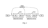
- FIG. 2 illustrates an example configuration of a long-range Ethernet connection.
- FIGS. 3A and 3B illustrate a circuit diagram that models the power over Ethernet system.
- FIGS. 4A and 4B illustrate real solutions that are available for the delivery of power to a powered device.
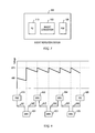
- FIG. 5 illustrates an embodiment of a boost repeater station according to the present invention.
- FIG. 6 illustrates an application of boost repeater stations to a long range Ethernet application.
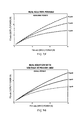
- FIGS. 7A and 7B illustrate real solutions that are available for the delivery of power to a powered device using integrated boost repeaters.
- repeater stations can be used to enhance the reach of data transmissions beyond the conventional 100 meter range.
- the repeater stations can also be self powered.
- the repeater station can include a PD that extracts power, provides some of that power for the extender circuitry, and sends the rest of the available power down the network cable to another repeater station or PD using a PSE.
- the long-range Ethernet connection can be broken up into multiple 100 meter cable segments that are coupled using a repeater station.
- FIG. 2 illustrates an example of such a long-range configuration.
- the repeater stations 210-1, 210-2 divide the long-range Ethernet connection into multiple cable segments.
- Each repeater station includes a PD that receives power from an upstream PSE, and a PSE that transmits the remainder of the received power to the downstream PD.
- the multiple cable segments are each 100 meters or less. As would be appreciated, the number of cable segments and the length of the individual segments can vary for a given long-range configuration.
- a power source provides a voltage V PSE to a circuit that includes a first parallel pair of resistors (R 1 , R 2 ), a load resistance R LOAD , and a second parallel pair of resistors (R 3 , R 4 ).
- the first parallel pair of resistors R 1 , R 2 represents the resistances of the TX pair of wires
- the second parallel pair of resistors R 3 , R 4 represents the resistances of the RX pair of wires.
- resistors R 1 , R 2 , R 3 , and R 4 depend on the type and length of network cable.
- the resistors R 1 , R 2 , R 3 , and R 4 can have a certain resistance/length that is dependent on a type of Ethernet cable (e.g., Category 3, 5, 6, etc.).
- a simplified PoE circuit model that includes the single cable resistance value R cable is illustrated in FIG. 3B .
- UVLO undervoltage lockout
- FIG. 4A illustrates the range of real solutions that are available for various 1-pair, 2-pair, and 4-pair powering scenarios assuming 1000 meters of A WG24 cable.
- the calculations illustrated in the possible real solutions of FIG. 4A did not consider the constraints represented by a UVLO of 30V.
- the current that is calculated for power slightly less than the above 6.033W is 0.234A
- the UVLO of 30V would require that the power be derated to about 5W so that the voltage at the PD-side would remain above the UVLO of 30V.
- FIG. 4B graphs the possible real solutions of power usable at the PD when constrained by the UVLO of 30V.
- the real solutions of the usable power illustrated in FIG. 4B represents a subset of the real solutions of the available power illustrated in FIG. 4A .
- the present invention seeks to remove the constraints that are evident in conventional long-range PoE applications by modifying the repeater stations that separate the long-range cable.
- boost repeater station 500 includes PD 510, PSE 520 and DC-DC boost converter 530.
- boost converter 530 can be designed to boost the voltage, which can thereby lower the current and the cable losses.
- boost converter 530 can be designed to boost the voltage received by PD 510 from an upstream PSE to 57V for output at PSE 520 to a downstream PD.
- boost converter 530 in a long-range PoE application is illustrated in FIG. 6 .
- the long-range cable that couples PSE 610 to PD 620 is broken into a plurality of cable segments 641-646. Adjacent cable segments are connected together via a boost repeater station (BRS).
- BRS boost repeater station
- PSE 610 outputs an initial output voltage of 48V onto the first cable segment 641.
- the initial 48V output gradually diminishes along the length of the first cable segment 641 until it reaches the first BRS 631.
- the boost converter module would then boost the voltage to 57V, which is then applied as an output voltage onto cable segment 642 by the PSE contained within BRS 631.
- This 57V output in turn would gradually diminish along the length of the second cable segment 642 until it reaches the second BRS 632.
- BRS 632 would boost the voltage back to 57V, which is then applied as an output voltage onto cable segment 643 by the PSE contained within BRS 632.
- this boosting process would continue at BRS 633, 634 and 635 in applying a boosted voltage to cable segments 644, 645, and 646, respectively.
- the end result of the voltage boosting at BRS 631-635 is a voltage received at PD 620 that is significantly higher than the UVLO of 30V.
- the benefits of boosting the voltage at the boost repeater station are significant.
- the simple benefits of boosting the voltage are that current decreases, and since losses in the cable are dependent on i 2 * R cable , then cable losses are reduced.
- FIGS. 7A and 7B illustrate the impact of boost-stage repeaters on the real solutions of usable and available power, respectively, even assuming that the boost converter efficiency is taken at 95%.
- boosting the voltage enables the system to almost double the available power at the end of the long-range cable.
- the usable power level at the end of the 1000 meter cable has gone up from a little over 5W (with no boost repeaters) to about 11W (with boost repeaters).
- no constraint on the available power that is actually usable at PD 620 would exist. This can be achieved because the use of a boost converter effectively removes the limitation that P PD ⁇ V 2 /(4 * R cable ).
Landscapes
- Engineering & Computer Science (AREA)
- Computer Networks & Wireless Communication (AREA)
- Signal Processing (AREA)
- Small-Scale Networks (AREA)
Applications Claiming Priority (1)
| Application Number | Priority Date | Filing Date | Title |
|---|---|---|---|
| US13/310,679 US20130145181A1 (en) | 2011-12-02 | 2011-12-02 | System and Method for Long Range Power Over Ethernet Using Integrated Boost Repeaters |
Publications (1)
| Publication Number | Publication Date |
|---|---|
| EP2600564A2 true EP2600564A2 (de) | 2013-06-05 |
Family
ID=46799954
Family Applications (1)
| Application Number | Title | Priority Date | Filing Date |
|---|---|---|---|
| EP12005846.6A Withdrawn EP2600564A2 (de) | 2011-12-02 | 2012-08-13 | System und Verfahren für weitreichende Leistung über Ethernet unter Verwendung von integrierten Boost-Repeatern |
Country Status (5)
| Country | Link |
|---|---|
| US (1) | US20130145181A1 (de) |
| EP (1) | EP2600564A2 (de) |
| KR (1) | KR20130062224A (de) |
| CN (1) | CN103138947A (de) |
| TW (1) | TW201325135A (de) |
Cited By (1)
| Publication number | Priority date | Publication date | Assignee | Title |
|---|---|---|---|---|
| EP4290809A1 (de) * | 2022-06-08 | 2023-12-13 | TE Connectivity Nederland B.V. | Aufteilungseinheit für eine einzige ethernet-hybridleitung und hybrides ethernet-leistungssystem |
Families Citing this family (7)
| Publication number | Priority date | Publication date | Assignee | Title |
|---|---|---|---|---|
| WO2015144457A1 (en) | 2014-03-24 | 2015-10-01 | Koninklijke Philips N.V. | Power-over-ethernet power distribution system |
| TWI621341B (zh) * | 2015-11-24 | 2018-04-11 | 知洋科技有限公司 | 用於網路供電之電子裝置與方法 |
| CN108768668A (zh) * | 2018-05-25 | 2018-11-06 | 英业达科技有限公司 | 电讯传输装置及方法 |
| CN110519068B (zh) * | 2019-08-15 | 2022-05-03 | 普联技术有限公司 | 一种poe供电控制装置和poe供电系统 |
| US11063630B2 (en) | 2019-11-01 | 2021-07-13 | Cisco Technology, Inc. | Initialization and synchronization for pulse power in a network system |
| CN112017420A (zh) * | 2020-08-27 | 2020-12-01 | 武汉中地恒达科技有限公司 | 一种工程监测传感器的信号增强及升压模块 |
| US12212379B2 (en) * | 2021-12-22 | 2025-01-28 | Legrand DPC, LLC | System for reducing power losses in communications cabling |
Family Cites Families (4)
| Publication number | Priority date | Publication date | Assignee | Title |
|---|---|---|---|---|
| US7873057B2 (en) * | 2005-04-26 | 2011-01-18 | Accedian Networks Inc. | Power over ethernet management devices and connection between ethernet devices |
| US20080290729A1 (en) * | 2007-05-24 | 2008-11-27 | Steve Alan Schoenberg | Ethernet interconnection apparatus and method |
| TWM346992U (en) * | 2008-07-09 | 2008-12-11 | Chung-Peng Lo | Power management system |
| US8261001B2 (en) * | 2009-04-27 | 2012-09-04 | Cisco Technology, Inc. | Network range extender device |
-
2011
- 2011-12-02 US US13/310,679 patent/US20130145181A1/en not_active Abandoned
-
2012
- 2012-08-13 EP EP12005846.6A patent/EP2600564A2/de not_active Withdrawn
- 2012-08-28 KR KR1020120094030A patent/KR20130062224A/ko not_active Abandoned
- 2012-09-12 TW TW101133333A patent/TW201325135A/zh unknown
- 2012-09-27 CN CN2012103662438A patent/CN103138947A/zh active Pending
Non-Patent Citations (1)
| Title |
|---|
| None |
Cited By (2)
| Publication number | Priority date | Publication date | Assignee | Title |
|---|---|---|---|---|
| EP4290809A1 (de) * | 2022-06-08 | 2023-12-13 | TE Connectivity Nederland B.V. | Aufteilungseinheit für eine einzige ethernet-hybridleitung und hybrides ethernet-leistungssystem |
| US12470417B2 (en) | 2022-06-08 | 2025-11-11 | Te Connectivity Germany Gmbh | Splitting unit for a single pair ethernet hybrid line and hybrid ethernet power system |
Also Published As
| Publication number | Publication date |
|---|---|
| TW201325135A (zh) | 2013-06-16 |
| US20130145181A1 (en) | 2013-06-06 |
| CN103138947A (zh) | 2013-06-05 |
| KR20130062224A (ko) | 2013-06-12 |
Similar Documents
| Publication | Publication Date | Title |
|---|---|---|
| EP2600564A2 (de) | System und Verfahren für weitreichende Leistung über Ethernet unter Verwendung von integrierten Boost-Repeatern | |
| CN103378975B (zh) | 单对以太网供电系统及装置 | |
| EP2693688B1 (de) | Kabelungleichsgewichtsdiagnostik zwischen Kanälen mit Doppelleitungspaaren für Leistung über Ethernetübertragung | |
| US8044747B2 (en) | Capacitor coupled Ethernet | |
| EP1928121B1 (de) | System und Verfahren zur Steuerung der Stromabgabe an eine stromgetriebene Vorrichtung auf Grundlage von Kanalhindernissen | |
| US7956616B2 (en) | System and method for measuring a cable resistance in a power over Ethernet application | |
| CN103812667B (zh) | 用于组合的以太网供电系统的极性校正桥控制器 | |
| US11005670B2 (en) | Low standby power circuit architecture for power saving within power source equipment | |
| US20050201306A1 (en) | Method and system for supplying power to multiple devices using power-transmitting network connections | |
| US20190106066A1 (en) | System, method and apparatus for one-pair power over ethernet in an automotive application | |
| US11533196B2 (en) | Regenerative power-over-ethernet (PoE) mid-span injector | |
| CN106256104A (zh) | 负载平衡的反向电源 | |
| EP2498444A1 (de) | System und Verfahren zum Austausch von Kanalinformationen und Informationen und Fähigkeiten bezüglich der physikalischen- und Datenschicht | |
| TWI667898B (zh) | 乙太網路供電遞送方法及系統 | |
| US20090222678A1 (en) | Active powered device for the application of power over ethernet | |
| US8050399B2 (en) | Power transformation device of a powered device in a power over ethernet system | |
| US20160134332A1 (en) | Using a power over ethernet device to supply multiple dc power to connected devices and application thereof | |
| US9998289B2 (en) | Apparatus and method for supplying power | |
| US12470418B2 (en) | Power status telemetry for powered devices in a system with power over ethernet | |
| CN101163018B (zh) | 用于一以太网供电系统的一受电端设备的电源转换装置 | |
| HK1182852A (en) | System and method for long range power over ethernet using integrated boost repeaters | |
| WO2007139576A9 (en) | Balancing current drawn from multiple power supply inputs using multiple-input inductors | |
| CN118054978A (zh) | 一种供电电路及网络设备 | |
| HK1191770A (en) | Cable imbalance diagnostics between channels that include wire pairs for power over ethernet transmission | |
| US20070157053A1 (en) | Power-switching circuit with overload protection from a serial bus interface and method of driving the same |
Legal Events
| Date | Code | Title | Description |
|---|---|---|---|
| PUAI | Public reference made under article 153(3) epc to a published international application that has entered the european phase |
Free format text: ORIGINAL CODE: 0009012 |
|
| 17P | Request for examination filed |
Effective date: 20120813 |
|
| AK | Designated contracting states |
Kind code of ref document: A2 Designated state(s): AL AT BE BG CH CY CZ DE DK EE ES FI FR GB GR HR HU IE IS IT LI LT LU LV MC MK MT NL NO PL PT RO RS SE SI SK SM TR |
|
| AX | Request for extension of the european patent |
Extension state: BA ME |
|
| STAA | Information on the status of an ep patent application or granted ep patent |
Free format text: STATUS: THE APPLICATION IS DEEMED TO BE WITHDRAWN |
|
| 18D | Application deemed to be withdrawn |
Effective date: 20150303 |