EP2600948B1 - Appareil d'exercice, utilisation d'un appareil d'exercice et procédé de contrôle de l'orientation de l'axe longitudinal du corps d'une personne - Google Patents
Appareil d'exercice, utilisation d'un appareil d'exercice et procédé de contrôle de l'orientation de l'axe longitudinal du corps d'une personne Download PDFInfo
- Publication number
- EP2600948B1 EP2600948B1 EP11746167.3A EP11746167A EP2600948B1 EP 2600948 B1 EP2600948 B1 EP 2600948B1 EP 11746167 A EP11746167 A EP 11746167A EP 2600948 B1 EP2600948 B1 EP 2600948B1
- Authority
- EP
- European Patent Office
- Prior art keywords
- person
- lateral faces
- distance
- practice device
- faces
- Prior art date
- Legal status (The legal status is an assumption and is not a legal conclusion. Google has not performed a legal analysis and makes no representation as to the accuracy of the status listed.)
- Not-in-force
Links
- 238000000034 method Methods 0.000 title claims description 11
- 210000000887 face Anatomy 0.000 claims 31
- 210000003128 head Anatomy 0.000 description 18
- 239000000758 substrate Substances 0.000 description 10
- 238000007373 indentation Methods 0.000 description 7
- 238000006073 displacement reaction Methods 0.000 description 3
- 239000003550 marker Substances 0.000 description 3
- JXYWFNAQESKDNC-BTJKTKAUSA-N (z)-4-hydroxy-4-oxobut-2-enoate;2-[(4-methoxyphenyl)methyl-pyridin-2-ylamino]ethyl-dimethylazanium Chemical compound OC(=O)\C=C/C(O)=O.C1=CC(OC)=CC=C1CN(CCN(C)C)C1=CC=CC=N1 JXYWFNAQESKDNC-BTJKTKAUSA-N 0.000 description 2
- 244000025254 Cannabis sativa Species 0.000 description 2
- 241000282412 Homo Species 0.000 description 2
- 239000003086 colorant Substances 0.000 description 2
- 230000008878 coupling Effects 0.000 description 2
- 238000010168 coupling process Methods 0.000 description 2
- 238000005859 coupling reaction Methods 0.000 description 2
- 239000000463 material Substances 0.000 description 2
- 230000000007 visual effect Effects 0.000 description 2
- 244000290594 Ficus sycomorus Species 0.000 description 1
- 244000269722 Thea sinensis Species 0.000 description 1
- 230000006978 adaptation Effects 0.000 description 1
- 230000002411 adverse Effects 0.000 description 1
- 230000000295 complement effect Effects 0.000 description 1
- 238000010276 construction Methods 0.000 description 1
- 230000006870 function Effects 0.000 description 1
- 210000004907 gland Anatomy 0.000 description 1
- 238000012423 maintenance Methods 0.000 description 1
- 239000002184 metal Substances 0.000 description 1
- 230000008447 perception Effects 0.000 description 1
- 239000004033 plastic Substances 0.000 description 1
- 229920003023 plastic Polymers 0.000 description 1
- 230000000284 resting effect Effects 0.000 description 1
- 239000004576 sand Substances 0.000 description 1
- 239000002023 wood Substances 0.000 description 1
Images



Classifications
-
- A—HUMAN NECESSITIES
- A63—SPORTS; GAMES; AMUSEMENTS
- A63B—APPARATUS FOR PHYSICAL TRAINING, GYMNASTICS, SWIMMING, CLIMBING, OR FENCING; BALL GAMES; TRAINING EQUIPMENT
- A63B69/00—Training appliances or apparatus for special sports
- A63B69/36—Training appliances or apparatus for special sports for golf
- A63B69/3623—Training appliances or apparatus for special sports for golf for driving
-
- A—HUMAN NECESSITIES
- A63—SPORTS; GAMES; AMUSEMENTS
- A63B—APPARATUS FOR PHYSICAL TRAINING, GYMNASTICS, SWIMMING, CLIMBING, OR FENCING; BALL GAMES; TRAINING EQUIPMENT
- A63B69/00—Training appliances or apparatus for special sports
- A63B69/36—Training appliances or apparatus for special sports for golf
- A63B69/3667—Golf stance aids, e.g. means for positioning a golfer's feet
-
- A—HUMAN NECESSITIES
- A63—SPORTS; GAMES; AMUSEMENTS
- A63B—APPARATUS FOR PHYSICAL TRAINING, GYMNASTICS, SWIMMING, CLIMBING, OR FENCING; BALL GAMES; TRAINING EQUIPMENT
- A63B69/00—Training appliances or apparatus for special sports
- A63B69/36—Training appliances or apparatus for special sports for golf
- A63B69/3623—Training appliances or apparatus for special sports for golf for driving
- A63B69/3629—Visual means not attached to the body for aligning, positioning the trainee's head or for detecting head movement, e.g. by parallax
-
- A—HUMAN NECESSITIES
- A63—SPORTS; GAMES; AMUSEMENTS
- A63B—APPARATUS FOR PHYSICAL TRAINING, GYMNASTICS, SWIMMING, CLIMBING, OR FENCING; BALL GAMES; TRAINING EQUIPMENT
- A63B2225/00—Miscellaneous features of sport apparatus, devices or equipment
- A63B2225/09—Adjustable dimensions
Definitions
- the invention relates to an exercise device for controlling the alignment of a particular body part or a body longitudinal axis of a person. Furthermore, the invention relates to the use of an exercise device. Finally, the invention relates to a method for aligning in particular the body longitudinal axis and / or a body part of a person relative to a substrate.
- a golf ball is hit by a person, especially a golfer, with the help of a golf club.
- Decisive for a purposeful and successful execution of a stroke is the so-called golf swing, with which the golf club is moved by the physical use of the person to the golf ball.
- a good golf swing is characterized by the fact that the bat is rotated with the help of the arms, the shoulder and the upper body around an imaginary axis, the so-called body longitudinal axis through the head and back wheel. In this case, a displacement of this axis during golf swing, for example, laterally or forward or backward by moving the upper body is largely undesirable.
- the maintenance of the axle in the golf swing is monitored by an observation of the golfer by another person, such as a golf instructor. This is necessary because the golfer himself has virtually no opportunity to observe the orientation of his own body axis during his movement. Thus, it is generally necessary to consult a second person for practicing. Thus, it is not possible, in particular, to independently improve his golf swing without the help of third parties.
- Object of the present invention is to provide a golfer an easy to handle exercise device, with the independent practice of golf swing is made possible.
- an exercise device which serves to control the orientation of a person, in particular a golfer, by the person himself.
- the alignment is made relative to the exercise device or to a substrate.
- the exercise device has a multi-surface main body with at least two side surfaces.
- means for setting up the exercise device are provided on a substrate. At least two of the side surfaces are aligned at least substantially perpendicular to an imaginary plane passing through the means for erecting. When placed on a surface this level then runs at least substantially parallel to the ground.
- the at least two side surfaces are arranged at a distance that corresponds at least substantially to an (average) human eye distance.
- the at least two sides are arranged to run perpendicular to an imaginary plane. This corresponds to a horizontal plane for placement on a surface. This causes the two side surfaces are perpendicular to the ground.
- the two side surfaces having a distance which corresponds approximately to a human eye distance, a person may preferably each with one of its two eyes along each of the side faces, ie with the left eye along a left side surface and the right eye along a right side surface. In this position of the head or the eyes, each of the two eyes is in the plane of one of the two side surfaces.
- an increasing surface portion of the side surface is visible instead of the upper edge of the side surfaces.
- the distance of the two side surfaces at least substantially corresponds to the eye relief of the person using.
- the distance is between 5 cm and 8 cm.
- the distance is approximately 6.5 cm.
- a distance of 6.5 cm corresponds to the average eye distance in humans. This is sufficient for most applications.
- the distance between the two side surfaces is designed variable. This can be done for example by a parallel displacement, in particular by means of a parallel feed, a ffergestlindes or the like.
- the distance can be set accordingly. Also exercise equipment with different distances for selection by a user or even custom-made exercise equipment are conceivable.
- the exercise device or the base body on several, in particular six, preferably eight outer surfaces. More preferably, the exercise device or the main body of the exercise device is polyhedron-shaped, truncated pyramidal, cuboid, cube-shaped or similar or has at least one corresponding basic shape. More preferably, at least one, preferably four, more preferably six, more preferably eight outer surfaces are present. At least two, preferably four of the outer surfaces are preferably formed as side surfaces. Preferably, an upper side and / or a lower side are present as outer surfaces. This corresponds to the particular six outer surfaces, which are present for example in a cuboid or cube.
- At least one of the outer surfaces are preferably at least as partially flat surfaces formed. More preferably, the outer surfaces are in particular arranged in pairs opposite and / or parallel to each other. Thus, the outer surfaces preferably form the outer walls or the outer boundary of the main body.
- the bottom is preferably used as a means of placing on the ground.
- the side surfaces are arranged at least in sections perpendicular to the means for setting up, in particular to the underside or to the ground. More preferably, the underside and / or the top are arranged at least substantially parallel to the ground.
- the side surfaces are formed as flat surfaces.
- the side surfaces are in particular formed as rectangular and / or square surfaces.
- the side surfaces are colored, preferably monochromatic, in particular homogeneous. This can be used, for example, signal colors, in particular the colors red, yellow, blue or the like.
- a color is chosen that stands out clearly from a commonly used surface.
- the underground is generally the game of green grass or yellowish sand of a golf course. Accordingly, the complementary color red can be well perceived.
- color blind for example, red-green blind persons, but also a different color, in particular yellow or blue can be provided, which ensures the strongest possible contrast to the ground and to the other surfaces of the exercise device.
- a mark is arranged on the upper side of the base body, preferably centrally.
- a marker for example, a bar, a dash, a recess or the like are used.
- the marking is preferably formed black.
- the dash is used to display the center of the body or the viewing direction of a user.
- the upper side of the main body is further preferably formed in a color which is as far as possible adaptable to the substrate and / or preferably in green.
- the training device or the base body is associated with an alignment indicator.
- the alignment indicator is preferably detachably connectable to the main body or exercise device. To connect to the main body is provided in particular in the same recess, opening or recording. The connection between the alignment indicator and the exercise device is preferably done by screwing, plugging or the like.
- the alignment indicator is preferably T-shaped. More preferably, the alignment indicator on several, in particular three with preferably rod and / or rod-shaped elements or rods. The elements are in particular releasably connectable, in particular in the region of a connecting part, such as a connecting sleeve.
- a rod serves to connect the base body with the connecting sleeve.
- the other two rods are collinear with each other and perpendicular to the base body opposite end portion of the rod connected to the same.
- the two collinear rods are arranged perpendicular to this rod.
- the outer surfaces, in particular the front side and / or the rear side preferably each have a recess or notch.
- This notch is particularly identical formed at the front and back.
- the notch is wedge-shaped and / or V-shaped.
- the cross-sectional area of the recess is preferably triangular, in particular in the form of an equilateral triangle.
- the recess is arranged centrally on the corresponding surface. More preferably, the recess extends over the entire side surface, preferably at least substantially in the vertical direction.
- the notch extends from the top to the bottom of the body.
- the recesses or indentations of two opposite side surfaces are aligned parallel to each other.
- the pointed together running side surfaces of the notch, so the two surface portions thereof, thus point towards the center of the body.
- they are opposite or opposite to each other.
- They preferably each point into the main body.
- the cross section in the horizontal direction of the notch may be, but need not be constant.
- the area size can vary with the same conditions.
- the notches or recesses provide that a deviation of the positioning in forward and backward direction by a person can be detected. The lateral deviations become visually recognizable or measurable by a more or less strong visibility of the side surfaces for the person.
- the surface portions of the notch are visible to varying degrees depending on the relative position of the observer. If the observer or the person is further in the direction of the rear side of the main body, the surface sections of the indentation there are visible as larger areas than those of the indentation of the front side. Accordingly, it can be counteracted by a shift in the direction of the center of the body, ie in the direction of the front. Positioning further towards the front leads correspondingly to a larger-area visibility of the local notch and a corresponding remedy in the opposite direction.
- each of the notches or recesses preferably has two preferably flat surfaces or surface sections.
- the surface sections preferably adjoin one another, in particular in the region of a common side edge. More preferably, the two adjacent surface portions are arranged at an angle to each other.
- the included angle between the two side surfaces is preferably between 0 ° and 180 °, preferably between 80 ° and 140 °. In particular, the angle for optimum function between 100 ° and 120 °, more preferably in about 110 °.
- the included between the surface portion and the associated outer surface angle is preferably between 0 ° and 90 °. In this case, preferably for optimum visibility between 30 ° and 40 °, in particular proposed in about 35 °.
- Preferably, in particular for better recognizability of the x-shaped design of the base body on the upper side of an x-shaped mark is attached. This preferably extends diagonally between opposite corners of the top.
- the exercise device and / or the main body is formed completely or partially in one piece.
- a one-piece design a very robust construction is ensured.
- this makes the decomposability reduced.
- a material come wood, plastics, metal and the like into consideration. Also combinations of different materials are conceivable.
- an exercise device is used to control the alignment, in particular of the body longitudinal axis and / or a body part of a person by the person himself. Accordingly, the person can be positioned relative to the exercise device or to position themselves and determine if necessary independently deviations from the ideal position or ideal position.
- the ideal position considered is a position that can be determined when the training device is set up on a substrate with side surfaces running at least substantially perpendicular to the ground. In the ideal position of the person, the person with both legs of the exercise device stands equally spaced on different sides. The upper body is angled slightly forward.
- the eyes are simultaneously positioned vertically above one of the side surfaces of the base body.
- the left eye is in the plane of the left side surface
- the right eye is in the plane of the right side surface. This can be verified by the fact that neither of the two side surfaces or the smallest possible proportion of them is visible.
- a laterally deviating positioning leads to a (stronger) visibility of the side surface in which the displacement has taken place. If the one eye of the person is on the left side of the left side surface, it is at least partially visible, while the right side surface is not or significantly less visible. If the eye distance coincides with the distance of the side surfaces of the exercise device, the person does not see the two side surfaces at all, or only their side edges, if they are ideally positioned above the side surfaces with the respective eyes.
- the page whose side surface is visible at all or at least to a greater extent than the other must be moved to the other side to improve the alignment. If both side surfaces are visible at the same time, even at an ideal or central position, this is the case the eye distance of the person is greater than the distance of the side surfaces. Then it must be ensured that for ideal alignment, the visible surface of both side surfaces is minimized. If the eye distance is smaller than the distance of the side surfaces, the result is an inaccuracy in the extent that the person's head can move between the two planes of the side surfaces, without one of the eyes can look laterally on the surface. In this area, therefore, no visual alignment with the side surfaces is possible.
- an adjustability of the side surface spacing or alternatively an optionally personalized embodiment of the exercise device is conceivable, in which the distance of the side surfaces is adapted to the distance of the eyes of the user or the person. Also, a suitable one can be selected from a number of prefabricated exercise devices with different distances of the side surfaces.
- a method for aligning a person relative to a ground having the features of claim 7 solves the above object.
- the person in particular a golfer, can be aligned with the aid of an exercise device according to the above statements or can orient himself.
- the exercise device has at least one, preferably two side surfaces, which are aligned at least substantially perpendicular to the ground.
- the side surfaces for the person become visible to varying degrees. This means that, depending on the positioning of the eyes, the side surfaces do not become recognizable as a more or less visible surface depending on the lateral deviation from the ideal position.
- the person can be moved in the opposite direction.
- the person or according to their head or upper body must be moved in the corresponding other direction away from the visible side surface.
- the side surfaces are considered simultaneously with one of the two eyes of the person.
- One of the two eyes is located in the plane of one side surface, while the other eye is arranged in the plane of the other side surface.
- the person is oriented so that he looks with one eye along a first side surface and with the second eye along the second side surface.
- the base body can be set up in such a way or positioned relative to a base that one eye of the person is located in each case one of the planes of the side surface, preferably above the base body, wherein preferably a vertical arrangement of the planes to the ground. This ensures that the alignment can be done by the person.
- the feet of the person are placed with the same distance on both sides of the exercise device that the axis through the head and upper body, the body longitudinal axis, in a vertical plane to the ground.
- the axis is inclined but due to the spaced from the base foot position forward.
- the visibility of the two side surfaces is simultaneously minimized by a body longitudinal axis of the person is displaced appropriately.
- it is preferably a simultaneous aiming, each with an eye along each one of the side surfaces. This corresponds to the arrangement of the eyes in one of the planes of the side surface.
- the exercise device or the base body preferably with a bottom, positioned on the ground, parked or stored.
- the underside is designed as a means for setting up and preferably at least almost or sections formed flat.
- the bottom or its contact points with the ground are thus arranged at least almost parallel to the ground.
- at least two side surfaces of the exercise device are arranged at least substantially perpendicular to the ground.
- the two side surfaces are aligned at least almost parallel to each other.
- this average distance to the alignment is sufficient.
- an adjustability can be provided for the exact adaptation to a user or, alternatively, a customized production of the exercise device can be made.
- the distance can also be set variably, depending on the eye relief of the user or the person.
- the exercise device is parked on a substrate such that the preferably parallel side surfaces are arranged at a preferably right angle to the ground. More preferably, the feet of the person with the same distance are each positioned laterally in the plane of the respective side surface. In particular, the middle between the eyes of the person is arranged vertically above the exercise device or is arranged there, so that the side surfaces are preferably not visible to the person or to the same extent.
- the Fig. 1 to 4 show an exercise device 10 as a first embodiment of the invention.
- the exercise device 10 consists practically only of a base body 12th
- This base body 12 is cube-shaped. Accordingly, the main body 12 has six outer surfaces 14.
- the outer surfaces 14 are formed identically in area and shape. These are each quadratic surfaces. In addition, the outer surfaces 14 are flat.
- each case two of the outer surfaces 14 are arranged parallel to each other on opposite sides of the base body 12. Where two of the outer surfaces 14 collide at the edge, there is a side edge 16. As a cube, the base body 12 has twelve of these side edges 16. In each case, the two outer surfaces 14 colliding at one of the twelve side edges 16 are perpendicular to each other.
- the front or rear outer surface 14, which is adjacent to the side surfaces 18 and 20 respectively, is also referred to as the front side 22 or the rear side 24 due to its arrangement.
- they are also colored homogeneously with a color generally deviating from the color of the side surfaces 18 and 20. This is for example a strong color like yellow or blue.
- the side surfaces 18 and 20, the front 22 and the back 24 the same color can be provided for all lateral outer surfaces 14 so.
- the lower outer surface 14 is formed as a bottom 26. With this bottom 26, the exercise device 10 is on a substrate 28. Thus, the bottom 26 serves as a means for placing on the ground 28. Due to the partially vertical arrangement of the outer surfaces 14 to each other, the side surfaces 18 and 20 as well as the front 22 and the back 24 vertically or vertically on the bottom 26 and thus the ground 28.
- the top surface 30 formed as the upper outer surface 14 is accordingly arranged parallel to the bottom 26 and thus parallel to the ground 28. For better visibility, the top 30 and possibly also the bottom 26 are provided with a deviating from the other outer surfaces 14 color.
- the upper side 30 has an in particular black marking 32.
- the marker 32 is formed as a straight strip, bar, stroke or as a recess. It extends in the direction of the upper side edge 16 of the front side 22 to the upper side edge 16 of the back 24. Here, it marks the middle between the upper side edge 16 of the side surface 18 and the upper side edge 16 of the side surface 20 and the left and right side edge 16 of the top 30.
- the viewing direction of a user usually runs along this marker 32nd
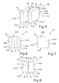
- the second embodiment of the invention is in the Fig. 5 to 8 shown. Again, the exercise device 10 has a base 12. In the following, only the deviations from the first exemplary embodiment will be described, since the basic structure is at least similar.
- the main body 12 of the second embodiment also shows a cube-shaped or cubic basic shape.
- at least parts of the outer surfaces 14 are arranged on the surface of a cube.
- notches 34 and 36 are present here.
- These indentations 34 and 36 each extend vertically or vertically when the exercise device 10 is set up on a substrate 28 with the underside 26.
- the indentations 34 and 36 jump back into the interior of the main body 12 relative to the respective sections of the front side 22 and the rear side 24 , So they extend from the outer surfaces 14 into the body 12.
- two additional surface portions 38 and 40 are provided as lateral boundary surfaces of the notches 34 and 36, respectively.
- the notches 34 and 36 are generally V-shaped or wedge-shaped.
- the angles at which the surface sections 38 and 40 extend angled relative to the front side 22 and the back side 24, respectively, are identical for all four surface sections 38 and 40.
- the surface portions 38 and 40 have the same area size. They are designed as flat, rectangular surfaces.
- the notches 34 and 36 pass through the two surfaces in each case.
- the base of the top 30 and the bottom 26 is still square.
- the two surfaces are not formed as square surfaces.
- triangular cutouts are provided on the edge side due to the wedge-shaped indentations 34 and 36, respectively.
- the side edges 16 in the region of the side surfaces 18 and 20 extend in sections and in the region of the front side 22 and the rear side 24 in each case along this square base surface. Only the Surface sections 38 and 40 intersect equilateral triangular sections from top 30 as well as bottom 26. Thus, the side edges 16 in this area run along the triangular cutouts.
- the surface portions 38 and 40 here include an angle of about 110 °. This corresponds to an angle between each of the surface portions 38 and 40 at each of the indentations 34 and 36 and the front side 22 and the rear side 24 of approximately 35 °.
- the four surfaces to be recognized in this view namely the left part of the front side 22, the surface parts 38 and 40 and the right part of the front side 22, are formed approximately equally wide in the frontal view.
- a change in the ratio of the width of the notch 34 or 36 to the edge regions 14, 22 is conceivable, however.
- the edge regions or sections of the front side 22 should each be of the same width, as well as the two surface portions 38 and 40. This ensures that on the one hand, a central arrangement of the notches 34 and 36 takes place and it is also a triangular equilateral basic shape or cross-sectional area of the cut-out wedge as a notch 34 and 36, respectively.
- FIGS. 9 and 10 based on the one in the Fig. 1 to 4 shown first embodiment. Accordingly, the base body 12 of the exercise apparatus 10 shown here is formed almost identical to that of the first embodiment. Alternatively, however, the main body 12 may be replaced, for example, by the main body 12 of the second embodiment or other alternative embodiments of the invention. The changes described below must then be made accordingly.
- the base body 12 is thus cubic here.
- An alignment indicator 42 is connected to it.
- This alignment indicator 42 is substantially T-shaped.
- three rods 44 and 46 are interconnected.
- the two rods 46 are connected to each other and with the perpendicular to this rod 44.
- the two rods 46 are aligned collinear with each other.
- the rods 44 and 46 are preferably inserted or screwed into the connecting sleeve 48.
- the coupling sleeve has three receptacles or openings 50 with preferably corresponding internal threads.
- the rods 44 and 46 have corresponding with these internal threads corresponding external thread. Thus, they are screwed into the connecting sleeve 48.
- connection sleeve 48 opposite end of the rod 44 is connected to the base body 12.
- the main body 12 has a receptacle or opening 52.
- the rod 44 can be inserted or used.
- an external thread is arranged corresponding to an internal thread in the opening 52 at the end region of the rod 44.
- the rod 44 can be screwed into the main body 12.
- a particularly snap-in connector or the like may also be provided here.
- the opening 52 is arranged at the lower region of the front side 22 of the main body in the vicinity of the lower side edge 16 to the underside 26.
- the opening 52 is provided centrally between the two side surfaces 18 and 20 in the lower region of the front side 22. Accordingly, the alignment indicator 42 is at least substantially substantially flat on the floor or ground 28 when it is connected to the base body 12 and this is placed with its bottom 26 on the ground 28.
- the alignment indicator 42 can be dismantled and thus easily transportable.
- the alignment indicator 42 is arranged by arranging a corresponding opening 52 in the region of the notch 34 of the base body 12, for example, the second embodiment also in a simple manner with selbigem or combined with other alternative embodiments of the invention.
- FIGS. 11 and 12 a person 60 outlined.
- the person 60 stands with her two feet 62 on the ground 28.
- Two substantially vertically aligned legs 64 support a slightly forward or inclined angled upper body 66.
- the upper body 66 is inclined forward so that a head 68 of the person 60 is located substantially above the main body 12 of the exercise device 10.
- two eyes 70 are positioned in the head 68 of the person 60 above the body 12.
- Person 60 is a golfer. Demenschend keeps the person 60 with their arms 72 a golf club 74 obliquely down towards the ground 28 directed. A club head 76 of the golf club 74 is located at height and next to a golf ball 78. The golf ball 78 is placed as usual on a small pen 80, the so-called “tea”, with a pointed end in the ground 28, for example, a grassy area of a golf course is plugged.
- the feet 62 of the person 60 are placed on the side facing away from the base 12 side of the two rods 46.
- the rod 44 and the connecting sleeve 48 is located substantially on a central line between the two feet 62. Due to the slight inclination of the upper body 66 forward reaches the head 68 of the person 60 above the body 12.
- the feet 62 are the same Distance each left or right side of an imaginary extension of the rod 44 placed over the connecting sleeve 48 addition.
- the upper body 66 is aligned with a body longitudinal axis 84 extending along the rod 44 in a vertical plane in the longitudinal direction of the rod 44, when the head 68 of the person 60 is located centrally above the base body 12 (s. Fig. 12 ).
- the body longitudinal axis 84 is no longer in the same vertical plane with the rod 44.
- the base 12 has a transverse dimension or a distance between the side surfaces 18 and 20, just the eye relief of the two eyes 70 of Person 60 corresponds. This is in Fig. 12 shown.
- the person 60 looks in ideal alignment on the one hand with one of the eyes 70 on each of the two side edges 16 of the side surface 18 and side surface 20. Accordingly, the person takes the respective side surface 18 or 20 only as a stroke in the form of the side edge 16 true.
- the feet 62 are arranged equidistantly on each side of the plane of the rod 44. In addition, they are spaced from the base body 12 placed in particular on the side facing away from the base 12 side of the rods 46.
- the body longitudinal axis 84 extends through upper body 66 and head 68 in a plane with the rod 44.
- the side surfaces 18 and 20 are designed in a contrasting color from the substrate 28. Since it is the ground 28 is usually a grassy area, it is often provided an intense color, such as the color red.
- the marking 32 on the upper side 30 of the main body 12 is used in all cases to display the lateral center of the body 12. It can serve as a further clue to the orientation of the person 60.
- the corresponding eye 70 arrives with its viewing direction next to the main body 12.
- the lateral position allows the person 60 with the eye 70 located laterally next to the base body 12 to slide obliquely from above onto the side surfaces 18 and 20 views.
- the side surface 18 and 20 is no longer perceived as a dash, but as increasing with increasing lateral deviation surface.
- the person 60 In order to correct the alignment of the body longitudinal axis 84, the person 60 only has to determine which of the two eyes 70 perceives one of the two surfaces 18 and 20 as a surface or which eye 70 perceives a larger surface. In the direction of the larger side surface 18 and 20, the eye 70 is therefore a lateral deviation from the center of the body 12 to the outside. To correct this deviation, the person 60 with his head 68 and accordingly the upper body 66 must therefore move in the opposite direction. This means that if the left eye 70 perceives a larger portion of the side surface 18 than the right eye 70 of the side surface 20, the person 60 must move to correct this deviation to the right in the direction of the side surface 20.
- the notches 34 and 36 of the second embodiment can serve.
- the surface sections 38 and 40 running obliquely inward with regard to the front side 22 and the rear side 24 respectively, the person 60 sees in a positioning of the eyes 70 in a line with the middle between the side edges 16 of the front side 22 and the rear side 24 Surface sections 38 and 40 as equal areas.
- the perceived ones change Areas of the surface portions 38 and 40.
- a forward movement causes the surface portions 38 and 40 of the back 24 of the body 12 are visible as larger areas, as those of the front side 22.
- it is correspondingly reversed. Accordingly, it can be determined with the aid of the exercise device 10, whether the body longitudinal axis 84 is optimally aligned to carry out a golf game. This can be done by the person 60 without the help of third parties.
Landscapes
- Health & Medical Sciences (AREA)
- General Health & Medical Sciences (AREA)
- Physical Education & Sports Medicine (AREA)
- Rehabilitation Tools (AREA)
- Golf Clubs (AREA)
- Measurement Of The Respiration, Hearing Ability, Form, And Blood Characteristics Of Living Organisms (AREA)
Claims (15)
- Appareil d'exercice permettant le contrôle de l'orientation d'une personne (60), en particulier d'un joueur de golf, par la personne (60) elle-même et par rapport à un soubassement (28), l'appareil présentant
un corps de base (12) à plusieurs surfaces présentant la forme de base d'un polyèdre présentant des surfaces extérieures (14) parallèles deux à deux, dont au moins certaines parties sont planes et parmi ces surfaces au moins deux surfaces latérales (18, 20), une face avant (22) et une face arrière (24), et des moyens de pose sur un soubassement (28),
au moins les surfaces latérales (18, 20), la face avant (22) et la face arrière (24) étant au moins essentiellement perpendiculaires à un plan imaginaire s'étendant à travers les moyens de pose,
caractérisé en ce que
les deux surfaces latérales opposées (18, 20) sont disposées à une distance qui correspond au moins essentiellement à la distance entre les yeux d'un être humain, à savoir entre 5 cm et 8 cm et
en ce que les deux surfaces latérales opposées (18, 20) présentent chacune une entaille (34, 36) dans la direction verticale. - Appareil d'exercice selon la revendication 1, caractérisé en ce que la distance entre la face avant (22) et la face arrière (24) correspond au moins essentiellement à la distance entre les yeux de la personne (60) qui l'utilise, est de préférence comprise entre 5 cm et 8 cm et est de façon particulièrement préférable d'environ 6,5 cm et/ou en ce que la distance entre les deux surfaces latérales (18, 20) peut être modifiée.
- Appareil d'exercice selon les revendications 1 ou 2, caractérisé en ce que le corps de base (12) présente plusieurs surfaces extérieures (14), de préférence six, et/ou en ce que le corps de base (12) présente la forme de base d'un parallélépipède rectangle et en particulier d'un cube présentant au moins six surfaces extérieures (14) qui sont configurées de préférence comme surfaces dont au moins certaines parties sont planes et/ou sont disposées l'une face à l'autre, en particulier par paires, de préférence avec une face supérieure (30) et une face inférieure (26).
- Appareil d'exercice selon l'une des revendications précédentes, caractérisé en ce qu'au moins les deux surfaces latérales (18, 20) sont configurées comme surfaces planes et/ou rectangulaires, de préférence carrées, et/ou en ce que les surfaces latérales (18, 20) sont disposées parallèlement l'une à l'autre.
- Appareil d'exercice selon l'une des revendications précédentes, caractérisé en ce que les surfaces latérales (18, 20) sont colorées, en ce que les surfaces latérales (18, 20) sont marquées et/ou décalées en couleur, de préférence de manière homogène, une couleur lumineuse, en particulier le rouge ou le jaune, étant prévue, et/ou en ce que la face supérieure (30) est colorée en vert.
- Appareil d'exercice selon l'une des revendications précédentes, caractérisé en ce qu'un repère (33), en particulier une barre, un trait, une découpe ou similaires, est disposé au niveau de la face supérieure (30) du corps de base (12), de préférence au milieu.
- Appareil d'exercice selon l'une des revendications précédentes, caractérisé en ce qu'un indicateur d'orientation (42), en particulier en forme de T, peut être relié de préférence de manière libérable au corps de base (12), en particulier par vissage, enfichage ou similaires, l'indicateur d'orientation (42) présentant de préférence plusieurs et en particulier trois éléments (44, 46), de préférence en forme de tige et/ou de barre, aptes à être reliés les uns aux autres de manière libérable, et/ou en ce que le corps de base (12) présente au moins un logement ou ouverture (52) destiné à reprendre la tige (44).
- Appareil d'exercice selon l'une des revendications précédentes, caractérisé en ce que l'entaille (34, 36) est disposée en particulier au milieu de chaque surface, en ce que l'entaille (34, 36) s'étend sur toute la surface, de préférence entre la face supérieure (30) et la face inférieure (26) et/ou en ce que les entailles (34, 36) de deux surfaces opposées s'étendent parallèlement l'une à l'autre, de préférence dans des orientations opposées, en étant tournées en particulier chacune vers l'intérieur du corps de base (12).
- Utilisation d'un appareil d'exercice (10) selon l'une des revendications précédentes pour le contrôle de l'orientation, en particulier de l'axe longitudinal (84) du corps et/ou d'une partie du corps d'une personne (60) par la personne (60) elle-même.
- Procédé d'orientation d'une personne (60), en particulier d'un joueur de golf, par rapport à un soubassement (28), à l'aide d'un appareil d'exercice (10), en particulier selon l'une des revendications précédentes, dans lequel au moins deux surfaces latérales (18, 20) mutuellement parallèles de l'appareil d'exercice (10), de préférence doté d'entailles (34, 36), sont orientées au moins essentiellement perpendiculairement au soubassement (28),
caractérisé en ce que
selon la position des yeux de la personne (60) par rapport à l'appareil d'exercice (10), les surfaces latérales (18, 20) et/ou les surfaces des entailles (34, 36) sont visibles dans différentes mesures par la personne (60), la distance entre les surfaces latérales (18, 20) étant adaptée à la distance moyenne entre les yeux d'une personne (60), et donc comprise entre environ 5 cm et 8 cm. - Procédé selon la revendication 10, caractérisé en ce que les surfaces extérieures (14) du corps de base (12), en particulier les surfaces latérales (18, 20), sont observées simultanément par l'un des deux yeux, en ce que la personne (60) est orientée de telle sorte qu'elle regarde ou puisse regarder d'un oeil (70) le long de la première surface latérale (18, 20) et de l'autre oeil (70) le long de la deuxième surface latérale (18, 20), en ce que le corps de base (12) peut être placé ou positionné par rapport à un soubassement de telle sorte qu'un oeil (70) de la personne (60) soit situé dans l'un des plans des surfaces latérales (18, 20), de préférence ait une orientation de préférence verticale par rapport au soubassement (28) et/ou en ce qu'au moins deux des surfaces latérales (18, 20) sont disposées de telle sorte qu'un écart de la position de la personne (60) par rapport à la position optimale puisse être détecté visuellement.
- Procédé selon les revendications 10 ou 11, caractérisé en ce que la distance entre deux surfaces latérales opposées (18, 20) est sélectionnée de telle sorte que la personne (60) puisse s'aligner en même temps avec l'un des yeux (70) sur l'une des deux surfaces latérales (18, 20), de préférence de telle sorte que pour un alignement central par rapport au corps de base (12), un même nombre de surfaces latérales (18, 20) puisse être vu des deux côtés, les deux surfaces latérales (18, 20) n'étant pas visibles ou étant visibles de manière minimale, et qu'en cas d'écart latéral même réduit par rapport à l'orientation angulaire correcte ou idéale de la personne (60), une plus grande surface d'au moins l'une des surfaces latérales (18, 20) puisse être visible de préférence au moins par l'un des deux yeux (70).
- Procédé selon l'une des revendications 10 à 12, caractérisé en ce que la distance entre les surfaces latérales opposées (18, 20) est fixée, en ce que la distance entre les surfaces latérales opposées (18, 20) est modifiée en particulier de manière continue pour l'adaptation à la distance entre les yeux de la personne (60) et/ou en ce que le degré et l'orientation de l'écart entre l'axe longitudinal (84) du corps par rapport à une orientation prédéterminée peut être détectée visuellement par la personne (60) à partir de la taille détectée des surfaces latérales (18, 20) ou de leur rapport mutuel.
- Procédé selon l'une des revendications 10 à 13, caractérisé en ce que par déplacement de l'axe longitudinal (84) du corps de la personne (60), la visibilité des deux surfaces latérales (18, 20) est minimisée en même temps, une orientation simultanée ayant lieu par chaque oeil (70) le long de chacune des surfaces latérales (18, 20).
- Procédé selon l'une des revendications 10 à 14, caractérisé en ce que l'appareil d'exercice (10) est placé sur le soubassement (28) et de préférence posé sur ce dernier, en particulier par une face inférieure (26) de préférence plane, en ce qu'au moins deux surfaces latérales (18, 20) de l'appareil d'exercice (10) sont disposées au moins essentiellement perpendiculairement au soubassement (28), de préférence au moins approximativement parallèlement l'une à l'autre, de préférence à une distance qui correspond à la distance moyenne entre les yeux d'une personne (60), à savoir entre 5 cm et 8 cm, de préférence d'environ 6,5 cm, la distance étant ajustée de préférence de manière variable en fonction de la distance entre les yeux de l'utilisateur ou de la personne (60), en ce que les pieds (62) de la personne (60) sont placés à même distance latérale à l'extérieur ou à côté du corps de base (12) et à côté du plan de chaque surface latérale (18, 20) et/ou en ce que le milieu entre les yeux (70) de la personne (60) est placé perpendiculairement au-dessus de l'appareil d'exercice (10), les surfaces latérales (18, 20) n'étant pas visibles ou étant visibles dans la même mesure.
Applications Claiming Priority (2)
| Application Number | Priority Date | Filing Date | Title |
|---|---|---|---|
| DE102010033475A DE102010033475A1 (de) | 2010-08-05 | 2010-08-05 | Übungsgerät, Verwendung eines Übungsgerätes und Verfahren zur Kontrolle der Ausrichtung einer Körperlängsachse einer Person |
| PCT/EP2011/003676 WO2012016643A2 (fr) | 2010-08-05 | 2011-07-22 | Appareil d'exercice, utilisation d'un appareil d'exercice et procédé de contrôle de l'orientation de l'axe longitudinal du corps d'une personne |
Publications (2)
| Publication Number | Publication Date |
|---|---|
| EP2600948A2 EP2600948A2 (fr) | 2013-06-12 |
| EP2600948B1 true EP2600948B1 (fr) | 2015-11-25 |
Family
ID=44509160
Family Applications (1)
| Application Number | Title | Priority Date | Filing Date |
|---|---|---|---|
| EP11746167.3A Not-in-force EP2600948B1 (fr) | 2010-08-05 | 2011-07-22 | Appareil d'exercice, utilisation d'un appareil d'exercice et procédé de contrôle de l'orientation de l'axe longitudinal du corps d'une personne |
Country Status (8)
| Country | Link |
|---|---|
| US (1) | US8951139B2 (fr) |
| EP (1) | EP2600948B1 (fr) |
| KR (1) | KR101557076B1 (fr) |
| CN (1) | CN103118747B (fr) |
| DE (1) | DE102010033475A1 (fr) |
| MY (1) | MY163849A (fr) |
| PH (1) | PH12013500229A1 (fr) |
| WO (1) | WO2012016643A2 (fr) |
Families Citing this family (1)
| Publication number | Priority date | Publication date | Assignee | Title |
|---|---|---|---|---|
| USD708285S1 (en) | 2014-02-06 | 2014-07-01 | Richard L Miller | Golf setup training device |
Family Cites Families (19)
| Publication number | Priority date | Publication date | Assignee | Title |
|---|---|---|---|---|
| US3857570A (en) * | 1974-04-24 | 1974-12-31 | M Gutierrez | Golf putting training device |
| US4032157A (en) * | 1976-02-13 | 1977-06-28 | Carpenter Walter M | Golfer's training device |
| US4194735A (en) * | 1978-03-08 | 1980-03-25 | Wilson Richard A | Batting stance and stride practice apparatus |
| JPH0411748Y2 (fr) * | 1984-11-20 | 1992-03-24 | ||
| US5007646A (en) * | 1990-07-31 | 1991-04-16 | Baber James A | Golf putting practice device |
| US5275570A (en) * | 1993-02-24 | 1994-01-04 | Hicks Bradford L | Golf instructional aid device |
| US5482284A (en) * | 1993-08-09 | 1996-01-09 | Vandever; Claude S. | Golf address and stance teaching and practice device |
| WO1996002304A1 (fr) * | 1994-07-19 | 1996-02-01 | Oscar Bevz | Dispositif indicateur de la ligne de vision pour l'execution d'un swing de golf |
| US5527037A (en) | 1994-10-07 | 1996-06-18 | Matsumoto; Robert | Golf training device |
| US5549298A (en) * | 1995-04-07 | 1996-08-27 | Cullen; Susan J. | Golf alignment apparatus |
| FR2735894B1 (fr) * | 1995-06-20 | 1997-10-31 | Jouan Dominique | Dispositif pour l'enseignement du golf |
| US6612937B1 (en) * | 1999-03-01 | 2003-09-02 | Michael Whelan | Golf swing sway indicator and trainer |
| DE10039494A1 (de) * | 2000-08-08 | 2002-02-21 | Colin Coughlan | Lernhilfe für Golf |
| US6440004B1 (en) | 2001-01-25 | 2002-08-27 | Ozzy Rodriguez | Golf stance and alignment device |
| US6722998B1 (en) * | 2003-03-05 | 2004-04-20 | Dale Miller Inc. | Method of applying putter alignment indicator to a putter |
| US7066825B1 (en) * | 2005-01-07 | 2006-06-27 | Inside Touch Inc. | Golf swing training aid and method of use of the same |
| US20070232406A1 (en) * | 2006-03-29 | 2007-10-04 | Grant Sybil B M | Swing cage |
| GB0812336D0 (en) * | 2008-07-04 | 2008-08-13 | Willis Stuart | Golf training device |
| CN101670175B (zh) * | 2008-09-12 | 2014-04-09 | 戴维·施穆茨 | 高尔夫推杆教学装置及方法 |
-
2010
- 2010-08-05 DE DE102010033475A patent/DE102010033475A1/de not_active Withdrawn
-
2011
- 2011-07-22 EP EP11746167.3A patent/EP2600948B1/fr not_active Not-in-force
- 2011-07-22 US US13/812,971 patent/US8951139B2/en active Active
- 2011-07-22 WO PCT/EP2011/003676 patent/WO2012016643A2/fr not_active Ceased
- 2011-07-22 PH PH1/2013/500229A patent/PH12013500229A1/en unknown
- 2011-07-22 CN CN201180045097.2A patent/CN103118747B/zh not_active Expired - Fee Related
- 2011-07-22 KR KR1020137004372A patent/KR101557076B1/ko not_active Expired - Fee Related
- 2011-07-22 MY MYPI2013000379A patent/MY163849A/en unknown
Also Published As
| Publication number | Publication date |
|---|---|
| CN103118747A (zh) | 2013-05-22 |
| KR20130070626A (ko) | 2013-06-27 |
| WO2012016643A3 (fr) | 2012-04-19 |
| US8951139B2 (en) | 2015-02-10 |
| CN103118747B (zh) | 2015-11-25 |
| WO2012016643A2 (fr) | 2012-02-09 |
| US20130130821A1 (en) | 2013-05-23 |
| MY163849A (en) | 2017-10-31 |
| PH12013500229A1 (en) | 2013-03-18 |
| EP2600948A2 (fr) | 2013-06-12 |
| DE102010033475A1 (de) | 2012-02-09 |
| KR101557076B1 (ko) | 2015-10-13 |
Similar Documents
| Publication | Publication Date | Title |
|---|---|---|
| DE3730861A1 (de) | Golfschlaeger | |
| DE29905273U1 (de) | Baseball-Übungsgerät | |
| DE202017003401U1 (de) | Golf-Putter aus Acrylglas | |
| EP2760553B1 (fr) | Procédé et dispositif d'entraînement au lancer | |
| EP2172250A1 (fr) | Station de raccord de lanceur | |
| EP2600948B1 (fr) | Appareil d'exercice, utilisation d'un appareil d'exercice et procédé de contrôle de l'orientation de l'axe longitudinal du corps d'une personne | |
| DE202012007179U1 (de) | Putter | |
| DE202008000861U1 (de) | Ausrichthilfe zum Putten | |
| DE202011106754U1 (de) | Golfputter mit Putterkopf | |
| DE10221437B4 (de) | Putt-Trainingsgerät | |
| WO2004098729A1 (fr) | Systeme de tapis d'entrainement pour le golf | |
| DE202013008343U1 (de) | Schlägerkopf für einen Golfschläger | |
| EP1952860B1 (fr) | Table de baby-foot avec un piétement mobile | |
| CH703035A2 (de) | Golftrainingsvorrichtung. | |
| DE102005048679B4 (de) | Vorrichtung zum Abbilden eines Winkels | |
| DE202024107616U1 (de) | Putting-Trainingsvorrichtung sowie Putter mit einer solchen | |
| DE202004006647U1 (de) | Golfputter | |
| DE212016000223U1 (de) | Landwirtschaftsmaschine zur Bodenkultivierung | |
| DE202017101513U1 (de) | Portable Schwungplatte | |
| DE20112868U1 (de) | Putter, insbesondere zu Übungszwecken | |
| DE102020133417A1 (de) | Trainingsgerät für Golfer | |
| DE10246952A1 (de) | Kick-Ballspiel-Vorrichtung | |
| DE20306365U1 (de) | Golfübungsgerät | |
| DE202005006173U1 (de) | Bande für Spielfelder, insbesondere Fußballspielfelder | |
| DE202016007255U1 (de) | Optische Ausrichtungshilfe für Golfschläger |
Legal Events
| Date | Code | Title | Description |
|---|---|---|---|
| PUAI | Public reference made under article 153(3) epc to a published international application that has entered the european phase |
Free format text: ORIGINAL CODE: 0009012 |
|
| 17P | Request for examination filed |
Effective date: 20130226 |
|
| AK | Designated contracting states |
Kind code of ref document: A2 Designated state(s): AL AT BE BG CH CY CZ DE DK EE ES FI FR GB GR HR HU IE IS IT LI LT LU LV MC MK MT NL NO PL PT RO RS SE SI SK SM TR |
|
| DAX | Request for extension of the european patent (deleted) | ||
| GRAP | Despatch of communication of intention to grant a patent |
Free format text: ORIGINAL CODE: EPIDOSNIGR1 |
|
| INTG | Intention to grant announced |
Effective date: 20150618 |
|
| GRAS | Grant fee paid |
Free format text: ORIGINAL CODE: EPIDOSNIGR3 |
|
| GRAA | (expected) grant |
Free format text: ORIGINAL CODE: 0009210 |
|
| AK | Designated contracting states |
Kind code of ref document: B1 Designated state(s): AL AT BE BG CH CY CZ DE DK EE ES FI FR GB GR HR HU IE IS IT LI LT LU LV MC MK MT NL NO PL PT RO RS SE SI SK SM TR |
|
| REG | Reference to a national code |
Ref country code: GB Ref legal event code: FG4D Free format text: NOT ENGLISH |
|
| REG | Reference to a national code |
Ref country code: CH Ref legal event code: EP |
|
| REG | Reference to a national code |
Ref country code: AT Ref legal event code: REF Ref document number: 762310 Country of ref document: AT Kind code of ref document: T Effective date: 20151215 |
|
| REG | Reference to a national code |
Ref country code: IE Ref legal event code: FG4D Free format text: LANGUAGE OF EP DOCUMENT: GERMAN |
|
| REG | Reference to a national code |
Ref country code: DE Ref legal event code: R096 Ref document number: 502011008426 Country of ref document: DE |
|
| REG | Reference to a national code |
Ref country code: LT Ref legal event code: MG4D |
|
| REG | Reference to a national code |
Ref country code: NL Ref legal event code: MP Effective date: 20160225 |
|
| PG25 | Lapsed in a contracting state [announced via postgrant information from national office to epo] |
Ref country code: NO Free format text: LAPSE BECAUSE OF FAILURE TO SUBMIT A TRANSLATION OF THE DESCRIPTION OR TO PAY THE FEE WITHIN THE PRESCRIBED TIME-LIMIT Effective date: 20160225 Ref country code: IS Free format text: LAPSE BECAUSE OF FAILURE TO SUBMIT A TRANSLATION OF THE DESCRIPTION OR TO PAY THE FEE WITHIN THE PRESCRIBED TIME-LIMIT Effective date: 20160325 Ref country code: NL Free format text: LAPSE BECAUSE OF FAILURE TO SUBMIT A TRANSLATION OF THE DESCRIPTION OR TO PAY THE FEE WITHIN THE PRESCRIBED TIME-LIMIT Effective date: 20151125 Ref country code: ES Free format text: LAPSE BECAUSE OF FAILURE TO SUBMIT A TRANSLATION OF THE DESCRIPTION OR TO PAY THE FEE WITHIN THE PRESCRIBED TIME-LIMIT Effective date: 20151125 Ref country code: LT Free format text: LAPSE BECAUSE OF FAILURE TO SUBMIT A TRANSLATION OF THE DESCRIPTION OR TO PAY THE FEE WITHIN THE PRESCRIBED TIME-LIMIT Effective date: 20151125 Ref country code: HR Free format text: LAPSE BECAUSE OF FAILURE TO SUBMIT A TRANSLATION OF THE DESCRIPTION OR TO PAY THE FEE WITHIN THE PRESCRIBED TIME-LIMIT Effective date: 20151125 |
|
| PG25 | Lapsed in a contracting state [announced via postgrant information from national office to epo] |
Ref country code: SE Free format text: LAPSE BECAUSE OF FAILURE TO SUBMIT A TRANSLATION OF THE DESCRIPTION OR TO PAY THE FEE WITHIN THE PRESCRIBED TIME-LIMIT Effective date: 20151125 Ref country code: FI Free format text: LAPSE BECAUSE OF FAILURE TO SUBMIT A TRANSLATION OF THE DESCRIPTION OR TO PAY THE FEE WITHIN THE PRESCRIBED TIME-LIMIT Effective date: 20151125 Ref country code: PL Free format text: LAPSE BECAUSE OF FAILURE TO SUBMIT A TRANSLATION OF THE DESCRIPTION OR TO PAY THE FEE WITHIN THE PRESCRIBED TIME-LIMIT Effective date: 20151125 Ref country code: LV Free format text: LAPSE BECAUSE OF FAILURE TO SUBMIT A TRANSLATION OF THE DESCRIPTION OR TO PAY THE FEE WITHIN THE PRESCRIBED TIME-LIMIT Effective date: 20151125 Ref country code: GR Free format text: LAPSE BECAUSE OF FAILURE TO SUBMIT A TRANSLATION OF THE DESCRIPTION OR TO PAY THE FEE WITHIN THE PRESCRIBED TIME-LIMIT Effective date: 20160226 Ref country code: PT Free format text: LAPSE BECAUSE OF FAILURE TO SUBMIT A TRANSLATION OF THE DESCRIPTION OR TO PAY THE FEE WITHIN THE PRESCRIBED TIME-LIMIT Effective date: 20160325 Ref country code: RS Free format text: LAPSE BECAUSE OF FAILURE TO SUBMIT A TRANSLATION OF THE DESCRIPTION OR TO PAY THE FEE WITHIN THE PRESCRIBED TIME-LIMIT Effective date: 20151125 |
|
| PG25 | Lapsed in a contracting state [announced via postgrant information from national office to epo] |
Ref country code: IT Free format text: LAPSE BECAUSE OF FAILURE TO SUBMIT A TRANSLATION OF THE DESCRIPTION OR TO PAY THE FEE WITHIN THE PRESCRIBED TIME-LIMIT Effective date: 20151125 Ref country code: CZ Free format text: LAPSE BECAUSE OF FAILURE TO SUBMIT A TRANSLATION OF THE DESCRIPTION OR TO PAY THE FEE WITHIN THE PRESCRIBED TIME-LIMIT Effective date: 20151125 |
|
| REG | Reference to a national code |
Ref country code: DE Ref legal event code: R097 Ref document number: 502011008426 Country of ref document: DE |
|
| PG25 | Lapsed in a contracting state [announced via postgrant information from national office to epo] |
Ref country code: SK Free format text: LAPSE BECAUSE OF FAILURE TO SUBMIT A TRANSLATION OF THE DESCRIPTION OR TO PAY THE FEE WITHIN THE PRESCRIBED TIME-LIMIT Effective date: 20151125 Ref country code: DK Free format text: LAPSE BECAUSE OF FAILURE TO SUBMIT A TRANSLATION OF THE DESCRIPTION OR TO PAY THE FEE WITHIN THE PRESCRIBED TIME-LIMIT Effective date: 20151125 Ref country code: SM Free format text: LAPSE BECAUSE OF FAILURE TO SUBMIT A TRANSLATION OF THE DESCRIPTION OR TO PAY THE FEE WITHIN THE PRESCRIBED TIME-LIMIT Effective date: 20151125 Ref country code: RO Free format text: LAPSE BECAUSE OF FAILURE TO SUBMIT A TRANSLATION OF THE DESCRIPTION OR TO PAY THE FEE WITHIN THE PRESCRIBED TIME-LIMIT Effective date: 20151125 Ref country code: EE Free format text: LAPSE BECAUSE OF FAILURE TO SUBMIT A TRANSLATION OF THE DESCRIPTION OR TO PAY THE FEE WITHIN THE PRESCRIBED TIME-LIMIT Effective date: 20151125 |
|
| PLBE | No opposition filed within time limit |
Free format text: ORIGINAL CODE: 0009261 |
|
| STAA | Information on the status of an ep patent application or granted ep patent |
Free format text: STATUS: NO OPPOSITION FILED WITHIN TIME LIMIT |
|
| PGFP | Annual fee paid to national office [announced via postgrant information from national office to epo] |
Ref country code: IE Payment date: 20160711 Year of fee payment: 6 |
|
| 26N | No opposition filed |
Effective date: 20160826 |
|
| PG25 | Lapsed in a contracting state [announced via postgrant information from national office to epo] |
Ref country code: SI Free format text: LAPSE BECAUSE OF FAILURE TO SUBMIT A TRANSLATION OF THE DESCRIPTION OR TO PAY THE FEE WITHIN THE PRESCRIBED TIME-LIMIT Effective date: 20151125 |
|
| PG25 | Lapsed in a contracting state [announced via postgrant information from national office to epo] |
Ref country code: BE Free format text: LAPSE BECAUSE OF NON-PAYMENT OF DUE FEES Effective date: 20160731 |
|
| REG | Reference to a national code |
Ref country code: CH Ref legal event code: PL |
|
| PG25 | Lapsed in a contracting state [announced via postgrant information from national office to epo] |
Ref country code: MC Free format text: LAPSE BECAUSE OF FAILURE TO SUBMIT A TRANSLATION OF THE DESCRIPTION OR TO PAY THE FEE WITHIN THE PRESCRIBED TIME-LIMIT Effective date: 20151125 |
|
| PG25 | Lapsed in a contracting state [announced via postgrant information from national office to epo] |
Ref country code: CH Free format text: LAPSE BECAUSE OF NON-PAYMENT OF DUE FEES Effective date: 20160731 Ref country code: FR Free format text: LAPSE BECAUSE OF NON-PAYMENT OF DUE FEES Effective date: 20160801 Ref country code: LI Free format text: LAPSE BECAUSE OF NON-PAYMENT OF DUE FEES Effective date: 20160731 |
|
| REG | Reference to a national code |
Ref country code: FR Ref legal event code: ST Effective date: 20170331 |
|
| PG25 | Lapsed in a contracting state [announced via postgrant information from national office to epo] |
Ref country code: LU Free format text: LAPSE BECAUSE OF NON-PAYMENT OF DUE FEES Effective date: 20160722 |
|
| REG | Reference to a national code |
Ref country code: AT Ref legal event code: MM01 Ref document number: 762310 Country of ref document: AT Kind code of ref document: T Effective date: 20160722 |
|
| PG25 | Lapsed in a contracting state [announced via postgrant information from national office to epo] |
Ref country code: AT Free format text: LAPSE BECAUSE OF NON-PAYMENT OF DUE FEES Effective date: 20160722 |
|
| REG | Reference to a national code |
Ref country code: IE Ref legal event code: MM4A |
|
| PG25 | Lapsed in a contracting state [announced via postgrant information from national office to epo] |
Ref country code: IE Free format text: LAPSE BECAUSE OF NON-PAYMENT OF DUE FEES Effective date: 20170722 |
|
| PG25 | Lapsed in a contracting state [announced via postgrant information from national office to epo] |
Ref country code: HU Free format text: LAPSE BECAUSE OF FAILURE TO SUBMIT A TRANSLATION OF THE DESCRIPTION OR TO PAY THE FEE WITHIN THE PRESCRIBED TIME-LIMIT; INVALID AB INITIO Effective date: 20110722 Ref country code: CY Free format text: LAPSE BECAUSE OF FAILURE TO SUBMIT A TRANSLATION OF THE DESCRIPTION OR TO PAY THE FEE WITHIN THE PRESCRIBED TIME-LIMIT Effective date: 20151125 |
|
| PG25 | Lapsed in a contracting state [announced via postgrant information from national office to epo] |
Ref country code: MT Free format text: LAPSE BECAUSE OF FAILURE TO SUBMIT A TRANSLATION OF THE DESCRIPTION OR TO PAY THE FEE WITHIN THE PRESCRIBED TIME-LIMIT Effective date: 20151125 Ref country code: MK Free format text: LAPSE BECAUSE OF FAILURE TO SUBMIT A TRANSLATION OF THE DESCRIPTION OR TO PAY THE FEE WITHIN THE PRESCRIBED TIME-LIMIT Effective date: 20151125 Ref country code: TR Free format text: LAPSE BECAUSE OF FAILURE TO SUBMIT A TRANSLATION OF THE DESCRIPTION OR TO PAY THE FEE WITHIN THE PRESCRIBED TIME-LIMIT Effective date: 20151125 |
|
| PG25 | Lapsed in a contracting state [announced via postgrant information from national office to epo] |
Ref country code: BG Free format text: LAPSE BECAUSE OF FAILURE TO SUBMIT A TRANSLATION OF THE DESCRIPTION OR TO PAY THE FEE WITHIN THE PRESCRIBED TIME-LIMIT Effective date: 20151125 |
|
| PG25 | Lapsed in a contracting state [announced via postgrant information from national office to epo] |
Ref country code: AL Free format text: LAPSE BECAUSE OF FAILURE TO SUBMIT A TRANSLATION OF THE DESCRIPTION OR TO PAY THE FEE WITHIN THE PRESCRIBED TIME-LIMIT Effective date: 20151125 |
|
| REG | Reference to a national code |
Ref country code: DE Ref legal event code: R082 Ref document number: 502011008426 Country of ref document: DE Representative=s name: DR. TRAEGER & STRAUTMANN PATENTANWAELTE PARTNE, DE |
|
| PGFP | Annual fee paid to national office [announced via postgrant information from national office to epo] |
Ref country code: GB Payment date: 20200127 Year of fee payment: 9 |
|
| PGFP | Annual fee paid to national office [announced via postgrant information from national office to epo] |
Ref country code: DE Payment date: 20200930 Year of fee payment: 10 |
|
| GBPC | Gb: european patent ceased through non-payment of renewal fee |
Effective date: 20200722 |
|
| PG25 | Lapsed in a contracting state [announced via postgrant information from national office to epo] |
Ref country code: GB Free format text: LAPSE BECAUSE OF NON-PAYMENT OF DUE FEES Effective date: 20200722 |
|
| REG | Reference to a national code |
Ref country code: DE Ref legal event code: R119 Ref document number: 502011008426 Country of ref document: DE |
|
| PG25 | Lapsed in a contracting state [announced via postgrant information from national office to epo] |
Ref country code: DE Free format text: LAPSE BECAUSE OF NON-PAYMENT OF DUE FEES Effective date: 20220201 |