EP2601022B1 - Maschine zum schneiden von stücken aus ovalen oder kugelförmigen früchten wie melonen oder wassermelonen - Google Patents
Maschine zum schneiden von stücken aus ovalen oder kugelförmigen früchten wie melonen oder wassermelonen Download PDFInfo
- Publication number
- EP2601022B1 EP2601022B1 EP11752343.1A EP11752343A EP2601022B1 EP 2601022 B1 EP2601022 B1 EP 2601022B1 EP 11752343 A EP11752343 A EP 11752343A EP 2601022 B1 EP2601022 B1 EP 2601022B1
- Authority
- EP
- European Patent Office
- Prior art keywords
- machine
- predisposed
- round
- round portion
- conveyor plane
- Prior art date
- Legal status (The legal status is an assumption and is not a legal conclusion. Google has not performed a legal analysis and makes no representation as to the accuracy of the status listed.)
- Active
Links
Images

Classifications
-
- B—PERFORMING OPERATIONS; TRANSPORTING
- B26—HAND CUTTING TOOLS; CUTTING; SEVERING
- B26D—CUTTING; DETAILS COMMON TO MACHINES FOR PERFORATING, PUNCHING, CUTTING-OUT, STAMPING-OUT OR SEVERING
- B26D5/00—Arrangements for operating and controlling machines or devices for cutting, cutting-out, stamping-out, punching, perforating, or severing by means other than cutting
- B26D5/20—Arrangements for operating and controlling machines or devices for cutting, cutting-out, stamping-out, punching, perforating, or severing by means other than cutting with interrelated action between the cutting member and work feed
- B26D5/30—Arrangements for operating and controlling machines or devices for cutting, cutting-out, stamping-out, punching, perforating, or severing by means other than cutting with interrelated action between the cutting member and work feed having the cutting member controlled by scanning a record carrier
- B26D5/34—Arrangements for operating and controlling machines or devices for cutting, cutting-out, stamping-out, punching, perforating, or severing by means other than cutting with interrelated action between the cutting member and work feed having the cutting member controlled by scanning a record carrier scanning being effected by a photosensitive device
-
- B—PERFORMING OPERATIONS; TRANSPORTING
- B26—HAND CUTTING TOOLS; CUTTING; SEVERING
- B26D—CUTTING; DETAILS COMMON TO MACHINES FOR PERFORATING, PUNCHING, CUTTING-OUT, STAMPING-OUT OR SEVERING
- B26D1/00—Cutting through work characterised by the nature or movement of the cutting member or particular materials not otherwise provided for; Apparatus or machines therefor; Cutting members therefor
- B26D1/01—Cutting through work characterised by the nature or movement of the cutting member or particular materials not otherwise provided for; Apparatus or machines therefor; Cutting members therefor involving a cutting member which does not travel with the work
- B26D1/04—Cutting through work characterised by the nature or movement of the cutting member or particular materials not otherwise provided for; Apparatus or machines therefor; Cutting members therefor involving a cutting member which does not travel with the work having a linearly-movable cutting member
- B26D1/06—Cutting through work characterised by the nature or movement of the cutting member or particular materials not otherwise provided for; Apparatus or machines therefor; Cutting members therefor involving a cutting member which does not travel with the work having a linearly-movable cutting member wherein the cutting member reciprocates
- B26D1/08—Cutting through work characterised by the nature or movement of the cutting member or particular materials not otherwise provided for; Apparatus or machines therefor; Cutting members therefor involving a cutting member which does not travel with the work having a linearly-movable cutting member wherein the cutting member reciprocates of the guillotine type
- B26D1/09—Cutting through work characterised by the nature or movement of the cutting member or particular materials not otherwise provided for; Apparatus or machines therefor; Cutting members therefor involving a cutting member which does not travel with the work having a linearly-movable cutting member wherein the cutting member reciprocates of the guillotine type with a plurality of cutting members
-
- B—PERFORMING OPERATIONS; TRANSPORTING
- B26—HAND CUTTING TOOLS; CUTTING; SEVERING
- B26D—CUTTING; DETAILS COMMON TO MACHINES FOR PERFORATING, PUNCHING, CUTTING-OUT, STAMPING-OUT OR SEVERING
- B26D3/00—Cutting work characterised by the nature of the cut made; Apparatus therefor
- B26D3/18—Cutting work characterised by the nature of the cut made; Apparatus therefor to obtain cubes or the like
- B26D3/185—Grid like cutters
-
- B—PERFORMING OPERATIONS; TRANSPORTING
- B26—HAND CUTTING TOOLS; CUTTING; SEVERING
- B26D—CUTTING; DETAILS COMMON TO MACHINES FOR PERFORATING, PUNCHING, CUTTING-OUT, STAMPING-OUT OR SEVERING
- B26D3/00—Cutting work characterised by the nature of the cut made; Apparatus therefor
- B26D3/24—Cutting work characterised by the nature of the cut made; Apparatus therefor to obtain segments other than slices, e.g. cutting pies
- B26D3/26—Cutting work characterised by the nature of the cut made; Apparatus therefor to obtain segments other than slices, e.g. cutting pies specially adapted for cutting fruit or vegetables, e.g. for onions
-
- B—PERFORMING OPERATIONS; TRANSPORTING
- B26—HAND CUTTING TOOLS; CUTTING; SEVERING
- B26D—CUTTING; DETAILS COMMON TO MACHINES FOR PERFORATING, PUNCHING, CUTTING-OUT, STAMPING-OUT OR SEVERING
- B26D3/00—Cutting work characterised by the nature of the cut made; Apparatus therefor
- B26D3/28—Splitting layers from work; Mutually separating layers by cutting
-
- B—PERFORMING OPERATIONS; TRANSPORTING
- B26—HAND CUTTING TOOLS; CUTTING; SEVERING
- B26D—CUTTING; DETAILS COMMON TO MACHINES FOR PERFORATING, PUNCHING, CUTTING-OUT, STAMPING-OUT OR SEVERING
- B26D5/00—Arrangements for operating and controlling machines or devices for cutting, cutting-out, stamping-out, punching, perforating, or severing by means other than cutting
- B26D5/007—Control means comprising cameras, vision or image processing systems
-
- B—PERFORMING OPERATIONS; TRANSPORTING
- B26—HAND CUTTING TOOLS; CUTTING; SEVERING
- B26D—CUTTING; DETAILS COMMON TO MACHINES FOR PERFORATING, PUNCHING, CUTTING-OUT, STAMPING-OUT OR SEVERING
- B26D7/00—Details of apparatus for cutting, cutting-out, stamping-out, punching, perforating, or severing by means other than cutting
- B26D7/06—Arrangements for feeding or delivering work of other than sheet, web, or filamentary form
- B26D7/0608—Arrangements for feeding or delivering work of other than sheet, web, or filamentary form by pushers
-
- B—PERFORMING OPERATIONS; TRANSPORTING
- B26—HAND CUTTING TOOLS; CUTTING; SEVERING
- B26D—CUTTING; DETAILS COMMON TO MACHINES FOR PERFORATING, PUNCHING, CUTTING-OUT, STAMPING-OUT OR SEVERING
- B26D7/00—Details of apparatus for cutting, cutting-out, stamping-out, punching, perforating, or severing by means other than cutting
- B26D7/06—Arrangements for feeding or delivering work of other than sheet, web, or filamentary form
- B26D7/0625—Arrangements for feeding or delivering work of other than sheet, web, or filamentary form by endless conveyors, e.g. belts
-
- B—PERFORMING OPERATIONS; TRANSPORTING
- B26—HAND CUTTING TOOLS; CUTTING; SEVERING
- B26D—CUTTING; DETAILS COMMON TO MACHINES FOR PERFORATING, PUNCHING, CUTTING-OUT, STAMPING-OUT OR SEVERING
- B26D9/00—Cutting apparatus combined with punching or perforating apparatus or with dissimilar cutting apparatus
-
- B—PERFORMING OPERATIONS; TRANSPORTING
- B26—HAND CUTTING TOOLS; CUTTING; SEVERING
- B26D—CUTTING; DETAILS COMMON TO MACHINES FOR PERFORATING, PUNCHING, CUTTING-OUT, STAMPING-OUT OR SEVERING
- B26D2210/00—Machines or methods used for cutting special materials
- B26D2210/02—Machines or methods used for cutting special materials for cutting food products, e.g. food slicers
-
- Y—GENERAL TAGGING OF NEW TECHNOLOGICAL DEVELOPMENTS; GENERAL TAGGING OF CROSS-SECTIONAL TECHNOLOGIES SPANNING OVER SEVERAL SECTIONS OF THE IPC; TECHNICAL SUBJECTS COVERED BY FORMER USPC CROSS-REFERENCE ART COLLECTIONS [XRACs] AND DIGESTS
- Y10—TECHNICAL SUBJECTS COVERED BY FORMER USPC
- Y10T—TECHNICAL SUBJECTS COVERED BY FORMER US CLASSIFICATION
- Y10T83/00—Cutting
- Y10T83/202—With product handling means
- Y10T83/2022—Initiated by means responsive to product or work
Definitions
- the present invention relates to a machine for the preparation of pieces of an oval or spherical fruit, such as a melon or watermelon.
- WO 2008/033741 discloses a machine for pattern cutting fruits, in which the product is cut into slices.
- the slices are arranged in series on a conveying mechanism and are imaged by a vision system in order to detect physical characteristics of each slice, including the presence of skin, peel, core, seeds and/or rot.
- the imaged slices are conveyed to a die cutter array, which selectively positions and activates one or more die cutters to create a desired cut-out shape.
- Such machine is quite slow in operation, since it requires the movement of several parts in order to cut a slice. Furthermore, only a single slice can be cut per time.
- the aim of the present invention is to provide a machine for the preparation of pieces of an oval or spherical fruit.
- the machine according to the present invention greatly speeds up the preparation of fruit pieces, as well as greatly reduces the waste of pulp.
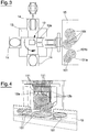
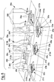
- the machine according to the present invention comprises a first cutting station 10, shown in detail in figures 3 and 4 , which is designed to cut a fruit 100 into round portions 101 in parallel planes.
- the first cutting station comprises a plurality of straight blades 11 arranged parallel to one another. These straight blades 11 are arranged vertically and are longitudinally mobile in an alternating straight motion by a motor mechanism not shown in detail since it is a device available to experts in the sector.
- the first cutting station 10 also comprises a pusher 12 predisposed to push a fruit 100 into contact with the straight blades 11.
- the pusher 12 includes a shoe 12a with a front surface intended to come into contact with a fruit 100.
- Such shoe is provided with a plurality of straight seats 12b destined to receive the straight blades 11 in such a way that the fruit 101 can be pushed by the pusher 12 to be traversed completely by the straight blades 11.
- the pusher 12 is movable between a first position, which is at a certain distance from the straight blades 11 and a fruit 100 can be positioned between the pusher 12 and the straight blades 11, and a second position, in which the straight blades are housed in the straight seats 12b and the front surface of the shoe 12 is located on the opposite side of the straight blades 11 with respect to the side it is on in the first position.
- a fruit 101 positioned between the pusher 12 and the straight blades 11 first comes into contact with the blades themselves, and is gradually cut according to parallel cutting planes defined by the straight blades themselves.
- the fruit 101 has been completely traversed by the straight blades 11 and is divided into round portions 101.
- a carousel 13 is predisposed to feed the fruits 100 in succession to the straight blades 11.
- the carousel 13 has at least two support elements 14 for at least two fruits 100.
- Each support element 14 is movable in rotation step by step, by the carousel 13, between at least one loading position, in which one fruit 100 can be placed on a support element 14, and a cutting position, where another fruit 100, placed on another support element 14, is located in an intermediate position between the pusher 12 and the straight blades 11 and can come in contact with the straight blades 11.
- the carousel 13 is equipped with four support elements 14 each separated by a regular angular pitch of 90°.
- a support element 14 is in the load position and another support element 14 is in cutting position, in correspondence with which the fruit 100 placed on the support element 14 can be pushed, by the pusher 12, into contact with the straight blades 11.
- a fruit 100 is then cut into round portions freeing the support element 14 on which the fruit is supported.
- the support element 14 can be loaded with another fruit 100.
- a conveyor plane 15 upon which the round portions 101 can be placed, either by falling directly from the first cutting station 10, or by another device or by the intervention of an operator.
- the machine according to the present invention comprises a second cutting station 20, shown in detail in figures 5 and 6 , which has two or more shaped blades 21a,b,c predisposed to cut the round portions 12 into prismatic fragments.
- the cutting of the round portions 101 occurs according to at least one axially symmetric surface, that separates the rind 101a from the pulp 101b, and a plurality of radial planes containing the central axis of symmetry of the axially symmetric surface.
- the shaped blades 21a,b,c comprise at least one external cutter 22a, b, c, with an axially symmetric shape, predisposed to separate the rind 101a from the pulp 101b of a round portion.
- This external cutter 22a,b,c has a central axis of symmetry x.
- the shaped blades also comprise at least one internal cutter 23a,b,c, with an axially symmetric shape, concentric to the external cutter 22a,b,c.
- a plurality of radial cutters 24a,b,c are variously arranged between the inner and outer edges 22,23a,b,c. These radial cutters are preferably oriented in a substantially radial direction with respect to the axis of symmetry x.
- the arrangement and orientation of the radial cutters 24a,b,c described and illustrated, can in any case be changed at will depending on the desired shape and dimensions for the prismatic fragments obtained by from the round portions 101.
- the external cutters 22a,b,c and internal cutters 23a,b,c are circular in shape, as shown in the accompanying figures.
- the external cutters 22a,b,c and internal cutters 23a,b,c could be constructed in a polygonal shape, which gives the prismatic fragments of fruit flat faces.
- the shaped blades 21a,b,c have different outer diameters from one another.
- the second cutting station 20 comprises three shaped blades.
- a first shaped blade 21a has a larger outer diameter
- a second shaped blade 21b has an intermediate outer diameter
- a third shaped blade 21c has a smaller outer diameter.
- the presence of shaped blades of different diameters is particularly useful to enable the cutting of round portions 101 of different diameters. It is clear that the round portions 101 cut from the central area of the fruit 100 have, by virtue of the oval or spherical shape of the fruit itself, an average diameter greater than round portions 101 cut from areas progressively farther from the central area of the fruit.
- the round portions 101 with a larger diameter may be cut by the first shaped blade 21a, the round portions 101 with a smaller diameter may be cut by the third shaped blade 21c and the round portions 101 with an intermediate diameter can be cut by the second shaped blade 21b.
- shaped blades with different diameters can also limit the thickness of the pulp that remains attached to the rind, since, for each round portion, it is possible to choose the shaped blade that comes closest to the innermost layer of the rind.
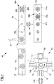
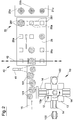
- the embodiment illustrated foresees the use of three shaped blades 21a,b,c the number of shaped blades may in any case be varied at will. A greater number of shaped blades further reduces the waste of pulp. A good compromise between the size and complexity of the machine and waste reduction is the use of five shaped blades, as shown in figure 1 .
- the shaped blades with a larger diameter in particular the first shaped blade 21a and the second shaped blade 21b can be fitted with an intermediate cutter 25a,b concentric to the external cutter 22a,b and the internal cutter 23a,b.
- the predisposition of an intermediate cutter, or further intermediate cutters enables the reduction of the size of the fragments of fruit cut from the round portions 101.
- the presence and number of intermediate cutters can be varied depending on the desired final size of the fragments of fruit.
- each shaped blade 21a,b,c there is a punch 29a,b,c, predisposed to press the round portions 100 on the shaped blades 21a,b,c.
- Each punch 29a,b,c is cyclically movable between a raised position, in which it is at some distance from its shaped blade 21a,b,c and in which a round portion 101 can be positioned on the shaped blade 21a,b,c, and a lowered position, where the round portion 101 is pressed into contact with the shaped blade 21a,b,c in order to be cut it into fragments.
- each punch 29a,b,c is equipped, on a front surface intended to come into contact with the round portions 101, with seats adapted to its shaped blade in such a way as to accommodate at least part of the height of the shaped blade. In this way, the entire thickness of each round portion 101 can be pushed through the shaped blade 21a,b,c, on which it rests.
- the shaped blades 21a,b,c are placed above an opening through which the fragments of fruit can fall into a container or another item or means of transportation.
- Four vertical cutting elements 210a,b,c, aligned two by two according to orthogonal planes are arranged on the outside of each shaped blade 21a,b,c to split the rind into four pieces that can subsequently be discarded.
- the rind of each round portion 101 would remain in an annular shape making it more difficult to manage.
- the second cutting station 20 also comprises a mobile conveyor plane 26 with a step by step forward motion predisposed to feed the round portions 101 on the shaped blades 21a,b,c.
- a mobile conveyor plane 26 with a step by step forward motion predisposed to feed the round portions 101 on the shaped blades 21a,b,c.
- the conveyor plane 26 has a plurality of support bases 26a to directly support the round portions 101.
- the support bases 26a are aligned along the feed direction of the conveyor plane 26, separated by a pitch equal to the feed pitch of the conveyor plane 26.
- the round portions 101 may be transferred from the first cutting station 10 to the conveyor plane 26 either by means of an automatic device, or, preferably, by a worker who picks up the round portions 101 from the conveyor plane 15 of the first cutting station and places them on the support bases 26a.
- the use of one person enables the direct examination of each round portion 101, so that the round portions 101 of unsuitable quality can be discarded directly.
- the machine according to the present invention also comprises a sorting device 40, predisposed to detect a diameter of the round portions 101 and direct each round portion to a shaped blade 21a,b,c, selected according to the diameter of each round portion 101.
- a sorting device 40 predisposed to detect a diameter of the round portions 101 and direct each round portion to a shaped blade 21a,b,c, selected according to the diameter of each round portion 101.
- the sorting device 40 can direct each round portion 101 to the most appropriate shaped blade 21a,b,c, or rather to the shaped blade whose outer diameter is closest to the measured diameter of the round portion, which preferably is the diameter of the pulp.
- the sorting device 40 comprises an optical detection device 41 predisposed to capture an image of the round portions 101 and to perform a measurement of the diameter of each round portion.
- the measurement may refer, for example, to the outer diameter of the round portion 101 relative to the face of the round portion facing upwards.
- the measurement may refer to the minimum diameter of the part to be discarded, composed of the rind and a layer adjacent to it, or to the maximum diameter of just the pulp.
- a processor is predisposed to manage the detections made by the optical detection device 41 so as to group the detections themselves into determined size ranges, each of which is associated with a particular shaped blade 21a,b,c.
- the optical detection device 41 is predisposed to perform several detections in succession each of which refers to a determined size range.
- the processor identifies a match between the detection made and a certain range, the appropriate shaped blade 21a,b,c is selected and the round portion 101 is sent to it.
- the shaped blades 21a,b,c are aligned parallel to the conveyor plane 26 of the second cutting station 20 and are located next to the conveyor plane 26 itself.
- the support bases are spaced apart by the same pitch that separates the shaped blades 21a,b,c. This allows for a support base 26a to be placed at the side of a shaped blade 21a,b,c in the stop positions for each forward pitch of the conveyor plane 26.
- each shaped blade 21a,b,c is associated with a certain range of size values. Each range of size values is associated in turn with one of the detections made in succession by the optical detection device 41.
- the shaped blades 21a,b,c are preferably arranged in a progressive order of size. For example, a first larger shaped blade 21a can be placed in the farthest position from the optical detection device 41, while the other shaped blades 21b,c are placed at progressively smaller distances. The minimum distance between one shaped blade and the optical detection device 41 is equal to one movement forward of the conveyor plane 26.
- the processor of the sorting device 40 is predisposed to know the position of each support base 26a of the conveyor plane 26. Since the support bases 26 are spaced apart with a regular pitch corresponding to the forward pitch of the conveyor plane 26, note the position of a first support base 26a at the initial start up of the machine and it is possible to know the position of that first support base 26a, and all other support bases 26a, by simply counting the number of forward pitches the conveyor plane 26 has taken, for example by means of an encoder. In this way, when the machine is fully operational and each support base 26a is occupied by a round portion 101, the processor is able to know the position and the range of size values of each round portion 101 downstream of the detection device 41. This enables the processor to determine at each forward pitch of the conveyor plane 26 if a round portion 101 is located next to the shaped blade 21a,b,c corresponding to the range of size values that has been detected for it by the detection device 41.
- the operation of the conveyor plane 26 is coordinated with the detections carried out by the detection device 41 as follows.
- a first round portion 101 positioned on a first support base 26a of the conveyor plane 26 is at the detection device 41.
- the processor assigns a starting position to this first support base 26a and the detection device 41 performs a first detection associated with the range of values corresponding to the largest shaped blade 21a. If the detection of the round portion 101 shows a size that falls in the range of values corresponding to the largest shaped blade 21a, the processor associates that range of size values to the first support base 26a.
- a second detection is taken associated with the range of values associated with the smaller shaped blade 21b. If the detection is positive, then the processor associates that range of smaller size values to the first support base 26a. If the detection is negative, a third measurement is conducted, and so on for the number of shaped blades present.
- the processor is able to know where the support base 26a is with the round portion 101 itself through the simple count of the forward pitches made by the conveyor plane 26. This is true of course for every support base 26a that, following the first, stops at the detection device 41.
- a positioning device 27 is predisposed to collect the round portions 101 from the conveyor plane 26 and to place the round portions 101 on the shaped blades 21a,b,c.
- This positioning device 27 comprises, for each shaped blade 21a,b,c, a shifter 28a,b,c equipped with gripping elements 280 that can be, for example, in the shape of plates or a group of fingers.
- the gripping elements 280 are predisposed to fit beneath the round portions 101, in a space defined by the support bases 26a between the conveyor plane 26 and the round portions 101 above.
- the gripping elements 280 are arranged above the conveyor plane 26 and project downwards.
- the gripping elements 280 if realized in the form of fingers, are equipped with appendages 281 at their lower ends predisposed in order to be inserted under the round portions 101 arranged on the support bases 26a.
- Each shifter 28a,b,c is movable between a gripping position, in which it is located above the conveyor plane 26, and a release position, in which it is above its shaped blade 21a,b,c.
- the gripping elements 280 of each shifter 28a,b,c are mobile approaching and moving away from one another from a narrow closed position, in which they can be arranged below a round portion 101, and a wide position in which they release the round portion 101.
- the gripping elements 280 are depicted in wide gripping position and narrow closed position.
- a first shifter 28a is shown in gripping position
- a second shifter 28b is shown in release position
- a third shifter 28c is in an intermediate position while taking a round portion 101 from the conveyor plane 26 to the corresponding shaped blade 28c.
- each shaped blade 21a,b,c has a support base 26a next to it.
- a support base 26a is bearing a round portion with dimensions that fall within the range of size values associated with the shaped blade it is next to in that moment, the shifter corresponding to that shaped blade is activated and the round portion 101 is transferred from the conveyor plane to the shaped blade 26. If, however, the size of the round portion does not fall within the range, the shifter is not activated and the round portion 101 continues to the next step, and so on for each forward pitch of the conveyor plane 26.
- the punches 29a,b,c move from the raised position to the lowered position to cut the round portions.
- the punches do their cycle of movement from the raised position to the lowered position and back stopping at every stop of the conveyor plane 26, regardless of the presence or absence of a round portion 101 on the corresponding shaped blade. Having a presence sensor at each shaped blade makes it possible to subordinate the action of each punch to the actual presence of a round portion 101.
- each shifter 28a,b,c starts from the release position.
- the shifter moves to the gripping position with the gripping elements 280 in a wide position.
- the gripping elements clasp together in the narrow closed position, grasping the round portion 101 as well, and the shifter moves to the release position above the shaped blade.
- the gripping elements are brought to the wide position, depositing the round portion 101 on the shaped blade 21a,b,c.
- the operational steps described are repeated cyclically during the operation of the machine.
- the support bases 26a are distributed in parallel rows each one aligned with one of the shaped blades 21a,b,c.
- the shaped blades 21a,b,c are at the output end of the conveyor plane 26 placed side by side and aligned transversely to the feed direction of the conveyor plane 26.
- the sorting device 40 comprises an diverter element 42a that is movable in a transverse direction with respect to the feed direction of the conveyor plane 26 of the second cutting station 20.
- This diverter element 42a is predisposed to move the round portions 101, coming from the conveyor plane 15 of the output of the first cutting station, in a transverse direction with respect to the direction of the conveyor plane 26 of the second cutting station 20, in such a way as to align each round portion 101 with the shaped blade to which it was assigned.
- an automatic transfer device between the first cutting station 10 and the second cutting station 20 is defined. This automatic transfer device independently directs the round portions 101 toward the most appropriate shaped blade 21a,b,c for cutting.
- the shifters 28a,b,c are movable in a direction parallel to the feed direction of the conveyor plane 26.
- each shifter 28a,b,c which is in its gripping position with the fingers in a wide position, is driven to bring the gripping elements 280 into the narrow closed position to pick up a round portion 101, if present on the respective support base 26a.
- each shifter moves towards the release position while the conveyor plane 26 is simultaneously activated to move a further step forward.
- the gripping elements 280 of each shifter 28a,b,c are activated into their wide position in which the round portion 101, if it has been grasped, can be placed on a shaped blade 21a,b,c.
- the punches 29a,b,c perform their cycle of movement from the raised position to the lowered position and back to the raised position.
- the operational steps described are repeated cyclically during operation of the machine.
- the round portions 101 travel along parallel lines and can reach the intended shaped blade 21a,b,c without interfering with the round portions 101 allocated to other shaped blades, it is not necessary for the processor of the sorting device 40, to know the position of the round portions 101 along the feed direction of the conveyor plane 26. Once each round portion 101 has been directed towards the right shaped blade 21a,b,c, no further control by the processor is required. The processor's control ends with the control of the diverter element 42a.
- the machine according to the present invention effectively achieves the intended objectives. In fact it enables the preparation of pieces from an oval or spherical fruit in a substantially automated way, limiting the use of operators to loading the fruit on the first cutting station and, possibly, for the simple transfer of round portions from the sorting device 40 to the conveyor plane 26 of the second cutting station.
- the cutting of fruit first into round portions 101 and then into prismatic pieces is particularly effective and considerably reduces the waste of pulp.
- the special shape of the shaped blades 21a,b,c enables the round portions 101 to be cut into well proportioned and regular prismatic pieces.
- the presence of multiple shaped blades 21a,b,c enables the waste of pulp to be limited.
Landscapes
- Engineering & Computer Science (AREA)
- Life Sciences & Earth Sciences (AREA)
- Forests & Forestry (AREA)
- Mechanical Engineering (AREA)
- Computer Vision & Pattern Recognition (AREA)
- Apparatuses For Bulk Treatment Of Fruits And Vegetables And Apparatuses For Preparing Feeds (AREA)
- Sorting Of Articles (AREA)
- Storage Of Fruits Or Vegetables (AREA)
- Preparation Of Fruits And Vegetables (AREA)
Claims (12)
- Maschine zum Vorbereiten von Stücken aus ovalen oder kugelförmigen Früchten wie Melonen oder Wassermelonen, umfassend: eine erste Schneidstation (10), die ausgelegt ist, um eine Frucht (100) in runde Abschnitte (101) in parallelen Ebenen zu schneiden; eine zweite Schneidstation (20), die mit zwei oder mehreren geformten Messern (21a, b, c) versehen ist, ausgelegt, um diese runden Abschnitte (101) in prismatische Fragmente zu schneiden, und parallel ausgerichtet zur Förderebene (26) durch eine Seite der Förderebene (26);
eine optische Erkennungsvorrichtung (41), die ausgelegt ist, um ein Bild der runden Abschnitte (101) zu erfassen und um eine Messung einer Größe eines jeden runden Abschnitts durchzuführen; einen Prozessor, der ausgelegt ist, um die durchgeführten Messungen mit einer Vielzahl an Größenbereichen zu vergleichen, von denen ein jeder mit einem geformten Messer (21a, b, c) assoziiert ist, und um ein Senden eines jeden runden Abschnitts (101) zum geformten Messer (21a, b, c) zu bewirken, assoziiert mit dem Größenbereich, unter den die am runden Abschnitt (101) durchgeführte Messung fällt,
wobei die zweite Schneidstation (20) eine Förderebene (26) umfasst, die mit einer Schrittbewegung entlang einer Vorwärtsrichtung (A) mobil ist, und der Prozessor ausgelegt ist, um die Vorwärtsvorschublängen der Förderebene (26) für einen jeden runden Abschnitt (101) zu zählen, dadurch gekennzeichnet, dass eine Positionierungsvorrichtung (27) ausgelegt ist, um die runden Abschnitte (101) von der Förderebene (26) aufzunehmen und einen jeden runden Abschnitt (101) auf dem geformten Messer (21a, b, c) abzulegen, assoziiert mit dem Größenbereich, unter den die am runden Abschnitt (101) durchgeführte Messung fällt. - Maschine nach Anspruch 1, wobei die optische Erkennungsvorrichtung (41) ausgelegt ist, um an einem jeden runden Abschnitt (101) eine Vielzahl aufeinanderfolgender Messungen durchzuführen, von denen eine jede mit einem Größenbereich verglichen wird, und um die nachfolgenden Messungen zu einem Zeitpunkt zu beenden, an dem eine Übereinstimmung zwischen einer durchgeführten Messung und einem der Größenbereiche erfasst wird.
- Maschine nach Anspruch 2, wobei der vom Prozessor durchgeführte Vergleich unter den an einem runden Abschnitt (101) durchgeführten Messungen und den in progressiven Größenordnungen berücksichtigten Größenbereichen erfolgt.
- Maschine nach Anspruch 1, wobei die Positionierungsvorrichtung (27) einen Schieber (28a, b, c) für ein jedes geformte Messer (21a, b, c) umfasst, wobei ein jeder Schieber (28a, b, c) ausgelegt ist, um einen runden Abschnitt (101) von der Förderebene (26) aufzunehmen und den runden Abschnitt (101) auf einem geformten Messer (21a, b, c) abzulegen, das am Schieber angeordnet ist, wobei die Aktivierung eines jeden Schiebers (28a, b, c) erfolgt, wenn der runde Abschnitt (101), der sich am Schieber befindet, eine Größe aufweist, die unter den Größenbereich fällt, der mit dem geformten Messer (21a, b, c), das am Schieber angeordnet ist, assoziiert ist.
- Maschine nach einem der vorhergehenden Ansprüche, wobei die geformten Messer (21a, b, c) an einem Ausgangsende der Förderebene (26) nebeneinander und quer ausgerichtet zur Vorwärtsrichtung der Förderebene (26) positioniert sind.
- Maschine nach einem der vorhergehenden Ansprüche, wobei die erste Schneidstation (10) eine Vielzahl an geraden Messern (11) umfasst, die parallel zueinander angeordnet sind.
- Maschine nach Anspruch 6, wobei die geraden Messer (11) längsseitig in einer geraden Pendelbewegung mobil sind.
- Maschine nach Anspruch 6 oder 7, wobei die erste Schneidstation (10) eine Schubvorrichtung (12) umfasst, die ausgelegt ist, um eine Frucht (100) in Kontakt mit den geraden Messern (11) zu schieben.
- Maschine nach einem der Ansprüche 6 bis 8, wobei die erste Schneidstation (10) ein Karussell (13) umfasst, das mit Halterungselementen (14) für mindestens zwei Früchte (100) versehen ist, wobei die Halterungselemente (14) in abgestufter Drehung mobil sind, durchgeführt durch das Karussell (13), zwischen mindestens einer Ladeposition, in der eine Frucht (100) auf einem Halterungselement (14) platziert werden kann, und einer Schneidposition, in der eine weitere Frucht (100), die auf einem weiteren Halterungselement (14) platziert ist, in Kontakt mit den geraden Messern (11) treten kann, sodass sie in runde Abschnitte (101) geschnitten wird.
- Maschine nach einem der vorhergehenden Ansprüche, wobei die geformten Messer (21a, b, c) der zweiten Schneidstation (20) umfassen: mindestens eine externe Schneideeinrichtung (22a, b, c), die ausgelegt ist, um eine Schale von einem Fruchtfleisch eines runden Abschnitts (101) zu trennen, und die eine mittige Symmetrieachse (x) aufweist; mindestens eine interne Schneideeinrichtung (23a, b, c), die konzentrisch zur externen Schneideeinrichtung (22a, b, c) angeordnet ist; eine Vielzahl an radialen Schneideeinrichtungen (24a, b, c), die zwischen der internen und externen Schneideeinrichtung angeordnet und in einer im Wesentlichen radialen Richtung zur mittigen Symmetrieachse (x) ausgerichtet sind.
- Maschine nach Anspruch 10, wobei die geformten Messer (21a, b, c) Außendurchmesser aufweisen, die voneinander abweichen.
- Maschine nach einem der vorhergehenden Ansprüche, wobei ein Presswerkzeug (29a, b, c) für ein jedes geformte Messer (21a, b, c) bereitgestellt ist, wobei das Presswerkzeug ausgelegt ist, um die runden Abschnitte (101) auf die geformten Messer (21a, b, c) zu pressen, sodass die runden Abschnitte von den geformten Messern (21a, b, c) in prismatische Fragmente geschnitten werden.
Applications Claiming Priority (2)
| Application Number | Priority Date | Filing Date | Title |
|---|---|---|---|
| IT000232A ITMO20100232A1 (it) | 2010-08-05 | 2010-08-05 | Macchina per la preparazione di pezzi da un frutto di forma ogivale o sferica, quale ad esempio un melone o un cocomero. |
| PCT/IB2011/053344 WO2012017356A1 (en) | 2010-08-05 | 2011-07-27 | A machine for the preparation of pieces of an oval or spherical fruit, such as melon or watermelon |
Publications (2)
| Publication Number | Publication Date |
|---|---|
| EP2601022A1 EP2601022A1 (de) | 2013-06-12 |
| EP2601022B1 true EP2601022B1 (de) | 2018-05-30 |
Family
ID=43735175
Family Applications (1)
| Application Number | Title | Priority Date | Filing Date |
|---|---|---|---|
| EP11752343.1A Active EP2601022B1 (de) | 2010-08-05 | 2011-07-27 | Maschine zum schneiden von stücken aus ovalen oder kugelförmigen früchten wie melonen oder wassermelonen |
Country Status (4)
| Country | Link |
|---|---|
| US (1) | US9180603B2 (de) |
| EP (1) | EP2601022B1 (de) |
| IT (1) | ITMO20100232A1 (de) |
| WO (1) | WO2012017356A1 (de) |
Cited By (1)
| Publication number | Priority date | Publication date | Assignee | Title |
|---|---|---|---|---|
| WO2024175795A3 (de) * | 2023-02-24 | 2024-11-28 | Weber Food Technology Gmbh | Verfahren und vorrichtungen zum schneiden von einem lebensmittelstück in mehrere kleinere stücke |
Families Citing this family (16)
| Publication number | Priority date | Publication date | Assignee | Title |
|---|---|---|---|---|
| US20130059044A1 (en) * | 2011-09-07 | 2013-03-07 | Cavendish Farms Corporation | Equipment and process for preparation of food products having closed loop continuous shapes |
| CN102699943A (zh) * | 2012-06-15 | 2012-10-03 | 徐州天顺农副产品有限公司 | 一种全自动牛蒡切削系统 |
| CN104602549A (zh) * | 2012-09-05 | 2015-05-06 | 阿特拉斯太平洋工程公司 | 水果分块和切条成形的方法和装置 |
| GB2532282A (en) * | 2014-11-17 | 2016-05-18 | Howgate Ltd | Slicing apparatus |
| ITUB20159245A1 (it) * | 2015-12-15 | 2017-06-15 | Mochi S R L | Macchina taglia frutta. |
| DE102016101753A1 (de) * | 2016-02-01 | 2017-08-03 | Textor Maschinenbau GmbH | Aufschneiden von lebensmittelprodukten |
| ITUB20160853A1 (it) * | 2016-02-18 | 2017-08-18 | Carlo Ascari | Dispositivo di taglio per prodotti ortofrutticoli |
| CN105583874B (zh) * | 2016-03-03 | 2017-08-11 | 浙江优诺食品股份有限公司 | 椰子切割机 |
| JP6622146B2 (ja) * | 2016-05-31 | 2019-12-18 | キユーピー株式会社 | 食品切断刃及びスティックサラダの製造方法 |
| CN107186764B (zh) * | 2017-06-28 | 2022-07-22 | 黄冈师范学院 | 一种食材切片生产线及其切片方法 |
| CN110785271A (zh) * | 2017-07-14 | 2020-02-11 | 比克维奥莱克斯公司 | 用于测量皮肤特性和增强剃刮体验的设备和方法 |
| CN109262681A (zh) * | 2018-11-02 | 2019-01-25 | 贵州忠意实业有限公司 | 成型机构 |
| CN109760129B (zh) * | 2019-02-26 | 2020-05-19 | 燕山大学 | 一种瓜果成型装置 |
| USD957880S1 (en) * | 2019-06-13 | 2022-07-19 | Lamb Weston, Inc. | Pusher for food products cutter |
| CN112571493B (zh) * | 2020-11-20 | 2022-06-24 | 恩施福硒康农业科技有限公司 | 一种制药用木瓜自动切块装置 |
| CN112873298B (zh) * | 2021-01-05 | 2023-06-13 | 山西古虞王农业股份有限公司 | 一种食品加工用果干制备切块装置 |
Family Cites Families (29)
| Publication number | Priority date | Publication date | Assignee | Title |
|---|---|---|---|---|
| US1317742A (en) * | 1919-10-07 | Planooftaph co | ||
| US13475A (en) * | 1855-08-21 | Charles ketcham | ||
| US153873A (en) * | 1874-08-04 | Improvement in saw-mills | ||
| US1361776A (en) * | 1920-02-18 | 1920-12-07 | Bernhard Gluck | Apparatus for and method of preparing vegetables and fruits |
| US1423490A (en) * | 1920-12-16 | 1922-07-18 | Vafiades George | Fruit seeder and slicer |
| US1999449A (en) * | 1932-03-22 | 1935-04-30 | Barron Gray Packing Company | Fruit and vegetable cutting device |
| US2127651A (en) * | 1937-04-23 | 1938-08-23 | Miller John H | Cake and pie crust perforator |
| US2635662A (en) * | 1949-07-11 | 1953-04-21 | S & W Fine Foods Inc | Fruit transport device for pitting machines |
| FR1583080A (de) * | 1968-07-16 | 1969-10-17 | ||
| NL7214736A (de) * | 1972-10-31 | 1974-05-02 | ||
| GB1427627A (en) * | 1973-02-15 | 1976-03-10 | Amf Inc | Slicing machines |
| US3955678A (en) * | 1974-08-09 | 1976-05-11 | American Chain & Cable Company, Inc. | Sorting system |
| US3929048A (en) * | 1974-11-11 | 1975-12-30 | John W Mcgehee | Reciprocating gang saw |
| ZA783198B (en) * | 1978-06-05 | 1979-09-26 | Sphere Invest | Improvements relating to sorting systems |
| US4812321A (en) * | 1985-06-10 | 1989-03-14 | Bridgford Foods Corporation | Method of subdividing dough |
| US4653393A (en) * | 1986-05-27 | 1987-03-31 | Del Monte Corporation | Apparatus for peeling pineapples |
| US4761291A (en) * | 1987-04-27 | 1988-08-02 | Neumann Industries, Incorporated | Pineapple processing method |
| FR2665336B1 (fr) * | 1990-08-03 | 1992-10-23 | Emsens Michel | Dispositif de coupe de tranches de viandes et/ou de legumes, pour la realisation de brochettes. |
| US5253765A (en) * | 1993-01-14 | 1993-10-19 | L.M.B. Electronics, Inc. | Sorting and grading system |
| NL1005537C2 (nl) * | 1997-03-14 | 1998-09-15 | Rompa Patent Beheer B V | Inrichting voor het in plakken snijden van broden en dergelijke bakkerijprodukten. |
| US5979281A (en) * | 1998-02-23 | 1999-11-09 | Caesar; Wayne W | Produce slicer and chopper device |
| EP1764195A3 (de) * | 2004-03-03 | 2007-07-11 | nv Verhaeghe-Decock | Vorrichtung zum Schneiden von Obst und Gemüse |
| DE102004013170B4 (de) * | 2004-03-17 | 2006-06-29 | Andreas Kerpers | Schneidevorrichtung zur Zerteilung von Früchten und Gemüse, insbesondere Zitrusfrüchten, in halbkreisförmige und gebrauchsfertige Scheiben |
| US7251537B1 (en) * | 2004-12-30 | 2007-07-31 | Fmc Technologies, Inc. | Processing of work piece based on desired end physical criteria |
| GB2421676B (en) * | 2004-12-30 | 2010-03-24 | Fmc Technologies | Portioning apparatus and method |
| WO2006086833A1 (en) * | 2005-02-15 | 2006-08-24 | Viapak Pty Ltd | Peeler and slicer apparatus |
| WO2008033741A2 (en) * | 2006-09-11 | 2008-03-20 | Sunkist Growers, Inc. | Method and apparatus for pattern cutting fruit |
| US8495941B2 (en) | 2008-02-01 | 2013-07-30 | Tariq Farid | Sectioning device and method of use |
| DE102010012727A1 (de) * | 2010-03-25 | 2011-09-29 | Weber Maschinenbau Gmbh Breidenbach | Vorrichtung zum Handhaben von Portionen aus Produkten |
-
2010
- 2010-08-05 IT IT000232A patent/ITMO20100232A1/it unknown
-
2011
- 2011-07-27 WO PCT/IB2011/053344 patent/WO2012017356A1/en not_active Ceased
- 2011-07-27 EP EP11752343.1A patent/EP2601022B1/de active Active
- 2011-07-27 US US13/700,544 patent/US9180603B2/en active Active
Non-Patent Citations (1)
| Title |
|---|
| None * |
Cited By (1)
| Publication number | Priority date | Publication date | Assignee | Title |
|---|---|---|---|---|
| WO2024175795A3 (de) * | 2023-02-24 | 2024-11-28 | Weber Food Technology Gmbh | Verfahren und vorrichtungen zum schneiden von einem lebensmittelstück in mehrere kleinere stücke |
Also Published As
| Publication number | Publication date |
|---|---|
| WO2012017356A1 (en) | 2012-02-09 |
| ITMO20100232A1 (it) | 2012-02-06 |
| US20130118326A1 (en) | 2013-05-16 |
| WO2012017356A4 (en) | 2012-03-29 |
| WO2012017356A9 (en) | 2012-05-24 |
| US9180603B2 (en) | 2015-11-10 |
| EP2601022A1 (de) | 2013-06-12 |
Similar Documents
| Publication | Publication Date | Title |
|---|---|---|
| US9180603B2 (en) | Machine for the preparation of pieces of an oval or spherical fruit, such as a melon or watermelon | |
| US4175690A (en) | Apparatus and method for producing sectioned edibles | |
| US10625330B2 (en) | Machine tools and methods for ejecting workpiece parts | |
| DE102015015166B4 (de) | Aufschnittschneidmaschine und Aufschnittschneidverfahren | |
| HK1205884A1 (en) | Fruit chunking and spear forming method and apparatus | |
| EP3539739B1 (de) | Maschine zum slicen in die packung | |
| CN114903185A (zh) | 一种食品处理设备及方法 | |
| WO2015128872A2 (en) | An improved machine for grading small sized irregular objects and a process thereof | |
| EP2354012B1 (de) | Vorrichtung und Verfahren zum Erstellen von Produktportionen | |
| WO2008033741A2 (en) | Method and apparatus for pattern cutting fruit | |
| US8622727B2 (en) | Apparatus and method for portioning food | |
| WO2015112345A1 (en) | Side loading pendulum slicer | |
| US3656527A (en) | Multilane fruit peeling system | |
| US9308685B2 (en) | Plastic bottle log trimmer and method | |
| USRE27807E (en) | Soyez machine for producing toothl xcks | |
| CN117260853A (zh) | 一种油杯管自动化裁切生产线 | |
| CN106457349B (zh) | 复式冲压装置 | |
| US20180020713A1 (en) | Fruit flesh extracting machine | |
| EP2916974B1 (de) | Stanzmaschine | |
| EP0312680A1 (de) | Automatische Vorrichtung zum Ausstanzen, zur Extraktion und zum Aufstellen von Nährungsmittelprodukten | |
| EP4623706B1 (de) | Maschine und verfahren zur automatischen vorbereitung einer ganzen ananas zum verzehr an einem ananas-verkaufsort | |
| DE19926188A1 (de) | Formgebung von Lebensmitteln mittels eines Schneidwerkzeuges | |
| JPH03268Y2 (de) | ||
| FI75088C (fi) | Saett och anlaeggning foer utformning av groensaker. | |
| DE10319707B3 (de) | Verpackungseinrichtung |
Legal Events
| Date | Code | Title | Description |
|---|---|---|---|
| PUAI | Public reference made under article 153(3) epc to a published international application that has entered the european phase |
Free format text: ORIGINAL CODE: 0009012 |
|
| 17P | Request for examination filed |
Effective date: 20121114 |
|
| AK | Designated contracting states |
Kind code of ref document: A1 Designated state(s): AL AT BE BG CH CY CZ DE DK EE ES FI FR GB GR HR HU IE IS IT LI LT LU LV MC MK MT NL NO PL PT RO RS SE SI SK SM TR |
|
| DAX | Request for extension of the european patent (deleted) | ||
| RAP1 | Party data changed (applicant data changed or rights of an application transferred) |
Owner name: A.B.L. S.P.A. |
|
| REG | Reference to a national code |
Ref country code: DE Ref legal event code: R079 Ref document number: 602011048822 Country of ref document: DE Free format text: PREVIOUS MAIN CLASS: B26D0003260000 Ipc: B26D0003180000 |
|
| RIC1 | Information provided on ipc code assigned before grant |
Ipc: B26D 3/28 20060101ALI20180129BHEP Ipc: B26D 1/09 20060101ALI20180129BHEP Ipc: B26D 9/00 20060101ALI20180129BHEP Ipc: B26D 3/18 20060101AFI20180129BHEP Ipc: B26D 5/00 20060101ALI20180129BHEP Ipc: B26D 3/26 20060101ALI20180129BHEP Ipc: B26D 7/06 20060101ALI20180129BHEP Ipc: B26D 5/34 20060101ALI20180129BHEP |
|
| GRAP | Despatch of communication of intention to grant a patent |
Free format text: ORIGINAL CODE: EPIDOSNIGR1 |
|
| INTG | Intention to grant announced |
Effective date: 20180319 |
|
| GRAS | Grant fee paid |
Free format text: ORIGINAL CODE: EPIDOSNIGR3 |
|
| GRAA | (expected) grant |
Free format text: ORIGINAL CODE: 0009210 |
|
| AK | Designated contracting states |
Kind code of ref document: B1 Designated state(s): AL AT BE BG CH CY CZ DE DK EE ES FI FR GB GR HR HU IE IS IT LI LT LU LV MC MK MT NL NO PL PT RO RS SE SI SK SM TR |
|
| REG | Reference to a national code |
Ref country code: GB Ref legal event code: FG4D |
|
| REG | Reference to a national code |
Ref country code: CH Ref legal event code: EP |
|
| REG | Reference to a national code |
Ref country code: AT Ref legal event code: REF Ref document number: 1003139 Country of ref document: AT Kind code of ref document: T Effective date: 20180615 |
|
| REG | Reference to a national code |
Ref country code: IE Ref legal event code: FG4D |
|
| REG | Reference to a national code |
Ref country code: DE Ref legal event code: R096 Ref document number: 602011048822 Country of ref document: DE |
|
| REG | Reference to a national code |
Ref country code: NL Ref legal event code: FP |
|
| REG | Reference to a national code |
Ref country code: LT Ref legal event code: MG4D |
|
| PG25 | Lapsed in a contracting state [announced via postgrant information from national office to epo] |
Ref country code: FI Free format text: LAPSE BECAUSE OF FAILURE TO SUBMIT A TRANSLATION OF THE DESCRIPTION OR TO PAY THE FEE WITHIN THE PRESCRIBED TIME-LIMIT Effective date: 20180530 Ref country code: BG Free format text: LAPSE BECAUSE OF FAILURE TO SUBMIT A TRANSLATION OF THE DESCRIPTION OR TO PAY THE FEE WITHIN THE PRESCRIBED TIME-LIMIT Effective date: 20180830 Ref country code: CY Free format text: LAPSE BECAUSE OF FAILURE TO SUBMIT A TRANSLATION OF THE DESCRIPTION OR TO PAY THE FEE WITHIN THE PRESCRIBED TIME-LIMIT Effective date: 20180530 Ref country code: LT Free format text: LAPSE BECAUSE OF FAILURE TO SUBMIT A TRANSLATION OF THE DESCRIPTION OR TO PAY THE FEE WITHIN THE PRESCRIBED TIME-LIMIT Effective date: 20180530 Ref country code: ES Free format text: LAPSE BECAUSE OF FAILURE TO SUBMIT A TRANSLATION OF THE DESCRIPTION OR TO PAY THE FEE WITHIN THE PRESCRIBED TIME-LIMIT Effective date: 20180530 Ref country code: SE Free format text: LAPSE BECAUSE OF FAILURE TO SUBMIT A TRANSLATION OF THE DESCRIPTION OR TO PAY THE FEE WITHIN THE PRESCRIBED TIME-LIMIT Effective date: 20180530 Ref country code: NO Free format text: LAPSE BECAUSE OF FAILURE TO SUBMIT A TRANSLATION OF THE DESCRIPTION OR TO PAY THE FEE WITHIN THE PRESCRIBED TIME-LIMIT Effective date: 20180830 |
|
| PG25 | Lapsed in a contracting state [announced via postgrant information from national office to epo] |
Ref country code: LV Free format text: LAPSE BECAUSE OF FAILURE TO SUBMIT A TRANSLATION OF THE DESCRIPTION OR TO PAY THE FEE WITHIN THE PRESCRIBED TIME-LIMIT Effective date: 20180530 Ref country code: HR Free format text: LAPSE BECAUSE OF FAILURE TO SUBMIT A TRANSLATION OF THE DESCRIPTION OR TO PAY THE FEE WITHIN THE PRESCRIBED TIME-LIMIT Effective date: 20180530 Ref country code: RS Free format text: LAPSE BECAUSE OF FAILURE TO SUBMIT A TRANSLATION OF THE DESCRIPTION OR TO PAY THE FEE WITHIN THE PRESCRIBED TIME-LIMIT Effective date: 20180530 Ref country code: GR Free format text: LAPSE BECAUSE OF FAILURE TO SUBMIT A TRANSLATION OF THE DESCRIPTION OR TO PAY THE FEE WITHIN THE PRESCRIBED TIME-LIMIT Effective date: 20180831 |
|
| REG | Reference to a national code |
Ref country code: AT Ref legal event code: MK05 Ref document number: 1003139 Country of ref document: AT Kind code of ref document: T Effective date: 20180530 |
|
| PG25 | Lapsed in a contracting state [announced via postgrant information from national office to epo] |
Ref country code: EE Free format text: LAPSE BECAUSE OF FAILURE TO SUBMIT A TRANSLATION OF THE DESCRIPTION OR TO PAY THE FEE WITHIN THE PRESCRIBED TIME-LIMIT Effective date: 20180530 Ref country code: SK Free format text: LAPSE BECAUSE OF FAILURE TO SUBMIT A TRANSLATION OF THE DESCRIPTION OR TO PAY THE FEE WITHIN THE PRESCRIBED TIME-LIMIT Effective date: 20180530 Ref country code: PL Free format text: LAPSE BECAUSE OF FAILURE TO SUBMIT A TRANSLATION OF THE DESCRIPTION OR TO PAY THE FEE WITHIN THE PRESCRIBED TIME-LIMIT Effective date: 20180530 Ref country code: CZ Free format text: LAPSE BECAUSE OF FAILURE TO SUBMIT A TRANSLATION OF THE DESCRIPTION OR TO PAY THE FEE WITHIN THE PRESCRIBED TIME-LIMIT Effective date: 20180530 Ref country code: RO Free format text: LAPSE BECAUSE OF FAILURE TO SUBMIT A TRANSLATION OF THE DESCRIPTION OR TO PAY THE FEE WITHIN THE PRESCRIBED TIME-LIMIT Effective date: 20180530 Ref country code: DK Free format text: LAPSE BECAUSE OF FAILURE TO SUBMIT A TRANSLATION OF THE DESCRIPTION OR TO PAY THE FEE WITHIN THE PRESCRIBED TIME-LIMIT Effective date: 20180530 Ref country code: AT Free format text: LAPSE BECAUSE OF FAILURE TO SUBMIT A TRANSLATION OF THE DESCRIPTION OR TO PAY THE FEE WITHIN THE PRESCRIBED TIME-LIMIT Effective date: 20180530 |
|
| PG25 | Lapsed in a contracting state [announced via postgrant information from national office to epo] |
Ref country code: SM Free format text: LAPSE BECAUSE OF FAILURE TO SUBMIT A TRANSLATION OF THE DESCRIPTION OR TO PAY THE FEE WITHIN THE PRESCRIBED TIME-LIMIT Effective date: 20180530 |
|
| REG | Reference to a national code |
Ref country code: CH Ref legal event code: PL |
|
| REG | Reference to a national code |
Ref country code: DE Ref legal event code: R097 Ref document number: 602011048822 Country of ref document: DE |
|
| PG25 | Lapsed in a contracting state [announced via postgrant information from national office to epo] |
Ref country code: MC Free format text: LAPSE BECAUSE OF FAILURE TO SUBMIT A TRANSLATION OF THE DESCRIPTION OR TO PAY THE FEE WITHIN THE PRESCRIBED TIME-LIMIT Effective date: 20180530 Ref country code: LU Free format text: LAPSE BECAUSE OF NON-PAYMENT OF DUE FEES Effective date: 20180727 |
|
| REG | Reference to a national code |
Ref country code: BE Ref legal event code: MM Effective date: 20180731 |
|
| PLBE | No opposition filed within time limit |
Free format text: ORIGINAL CODE: 0009261 |
|
| STAA | Information on the status of an ep patent application or granted ep patent |
Free format text: STATUS: NO OPPOSITION FILED WITHIN TIME LIMIT |
|
| PG25 | Lapsed in a contracting state [announced via postgrant information from national office to epo] |
Ref country code: FR Free format text: LAPSE BECAUSE OF NON-PAYMENT OF DUE FEES Effective date: 20180730 Ref country code: LI Free format text: LAPSE BECAUSE OF NON-PAYMENT OF DUE FEES Effective date: 20180731 Ref country code: CH Free format text: LAPSE BECAUSE OF NON-PAYMENT OF DUE FEES Effective date: 20180731 |
|
| REG | Reference to a national code |
Ref country code: IE Ref legal event code: MM4A |
|
| 26N | No opposition filed |
Effective date: 20190301 |
|
| PG25 | Lapsed in a contracting state [announced via postgrant information from national office to epo] |
Ref country code: SI Free format text: LAPSE BECAUSE OF FAILURE TO SUBMIT A TRANSLATION OF THE DESCRIPTION OR TO PAY THE FEE WITHIN THE PRESCRIBED TIME-LIMIT Effective date: 20180530 Ref country code: BE Free format text: LAPSE BECAUSE OF NON-PAYMENT OF DUE FEES Effective date: 20180731 |
|
| PG25 | Lapsed in a contracting state [announced via postgrant information from national office to epo] |
Ref country code: IE Free format text: LAPSE BECAUSE OF NON-PAYMENT OF DUE FEES Effective date: 20180727 |
|
| PG25 | Lapsed in a contracting state [announced via postgrant information from national office to epo] |
Ref country code: AL Free format text: LAPSE BECAUSE OF FAILURE TO SUBMIT A TRANSLATION OF THE DESCRIPTION OR TO PAY THE FEE WITHIN THE PRESCRIBED TIME-LIMIT Effective date: 20180530 |
|
| PG25 | Lapsed in a contracting state [announced via postgrant information from national office to epo] |
Ref country code: MT Free format text: LAPSE BECAUSE OF NON-PAYMENT OF DUE FEES Effective date: 20180727 |
|
| PG25 | Lapsed in a contracting state [announced via postgrant information from national office to epo] |
Ref country code: TR Free format text: LAPSE BECAUSE OF FAILURE TO SUBMIT A TRANSLATION OF THE DESCRIPTION OR TO PAY THE FEE WITHIN THE PRESCRIBED TIME-LIMIT Effective date: 20180530 |
|
| PG25 | Lapsed in a contracting state [announced via postgrant information from national office to epo] |
Ref country code: HU Free format text: LAPSE BECAUSE OF FAILURE TO SUBMIT A TRANSLATION OF THE DESCRIPTION OR TO PAY THE FEE WITHIN THE PRESCRIBED TIME-LIMIT; INVALID AB INITIO Effective date: 20110727 Ref country code: PT Free format text: LAPSE BECAUSE OF FAILURE TO SUBMIT A TRANSLATION OF THE DESCRIPTION OR TO PAY THE FEE WITHIN THE PRESCRIBED TIME-LIMIT Effective date: 20180530 |
|
| PG25 | Lapsed in a contracting state [announced via postgrant information from national office to epo] |
Ref country code: MK Free format text: LAPSE BECAUSE OF NON-PAYMENT OF DUE FEES Effective date: 20180530 |
|
| PG25 | Lapsed in a contracting state [announced via postgrant information from national office to epo] |
Ref country code: IS Free format text: LAPSE BECAUSE OF FAILURE TO SUBMIT A TRANSLATION OF THE DESCRIPTION OR TO PAY THE FEE WITHIN THE PRESCRIBED TIME-LIMIT Effective date: 20180930 |
|
| REG | Reference to a national code |
Ref country code: DE Ref legal event code: R082 Ref document number: 602011048822 Country of ref document: DE Representative=s name: MANITZ FINSTERWALD PATENT- UND RECHTSANWALTSPA, DE Ref country code: DE Ref legal event code: R081 Ref document number: 602011048822 Country of ref document: DE Owner name: A.B.L. S.R.L., IT Free format text: FORMER OWNER: A.B.L. S.P.A., CAVEZZO, MODENA, IT |
|
| REG | Reference to a national code |
Ref country code: NL Ref legal event code: PD Owner name: A.B.L. S.R.L.; IT Free format text: DETAILS ASSIGNMENT: CHANGE OF OWNER(S), CHANGE OF LEGAL ENTITY; FORMER OWNER NAME: A.B.L. S.P.A. Effective date: 20210817 |
|
| P01 | Opt-out of the competence of the unified patent court (upc) registered |
Effective date: 20230530 |
|
| PGFP | Annual fee paid to national office [announced via postgrant information from national office to epo] |
Ref country code: NL Payment date: 20250724 Year of fee payment: 15 |
|
| PGFP | Annual fee paid to national office [announced via postgrant information from national office to epo] |
Ref country code: DE Payment date: 20250728 Year of fee payment: 15 |
|
| PGFP | Annual fee paid to national office [announced via postgrant information from national office to epo] |
Ref country code: IT Payment date: 20250728 Year of fee payment: 15 |
|
| PGFP | Annual fee paid to national office [announced via postgrant information from national office to epo] |
Ref country code: GB Payment date: 20250722 Year of fee payment: 15 |