EP2601371B1 - Einspannvorrichtung - Google Patents
Einspannvorrichtung Download PDFInfo
- Publication number
- EP2601371B1 EP2601371B1 EP11757527.4A EP11757527A EP2601371B1 EP 2601371 B1 EP2601371 B1 EP 2601371B1 EP 11757527 A EP11757527 A EP 11757527A EP 2601371 B1 EP2601371 B1 EP 2601371B1
- Authority
- EP
- European Patent Office
- Prior art keywords
- adjusting
- elements
- corner
- opening
- clamping device
- Prior art date
- Legal status (The legal status is an assumption and is not a legal conclusion. Google has not performed a legal analysis and makes no representation as to the accuracy of the status listed.)
- Active
Links
Images



Classifications
-
- E—FIXED CONSTRUCTIONS
- E06—DOORS, WINDOWS, SHUTTERS, OR ROLLER BLINDS IN GENERAL; LADDERS
- E06B—FIXED OR MOVABLE CLOSURES FOR OPENINGS IN BUILDINGS, VEHICLES, FENCES OR LIKE ENCLOSURES IN GENERAL, e.g. DOORS, WINDOWS, BLINDS, GATES
- E06B9/00—Screening or protective devices for wall or similar openings, with or without operating or securing mechanisms; Closures of similar construction
- E06B9/02—Shutters, movable grilles, or other safety closing devices, e.g. against burglary
-
- E—FIXED CONSTRUCTIONS
- E06—DOORS, WINDOWS, SHUTTERS, OR ROLLER BLINDS IN GENERAL; LADDERS
- E06B—FIXED OR MOVABLE CLOSURES FOR OPENINGS IN BUILDINGS, VEHICLES, FENCES OR LIKE ENCLOSURES IN GENERAL, e.g. DOORS, WINDOWS, BLINDS, GATES
- E06B9/00—Screening or protective devices for wall or similar openings, with or without operating or securing mechanisms; Closures of similar construction
- E06B2009/007—Flood panels
-
- Y—GENERAL TAGGING OF NEW TECHNOLOGICAL DEVELOPMENTS; GENERAL TAGGING OF CROSS-SECTIONAL TECHNOLOGIES SPANNING OVER SEVERAL SECTIONS OF THE IPC; TECHNICAL SUBJECTS COVERED BY FORMER USPC CROSS-REFERENCE ART COLLECTIONS [XRACs] AND DIGESTS
- Y10—TECHNICAL SUBJECTS COVERED BY FORMER USPC
- Y10T—TECHNICAL SUBJECTS COVERED BY FORMER US CLASSIFICATION
- Y10T403/00—Joints and connections
- Y10T403/70—Interfitted members
- Y10T403/7062—Clamped members
Definitions
- This invention relates to a clamping device clampable in an opening, the clamping device comprising at least one corner element, a side element, adjusting devices and a clamping device connected to the side element via one of the adjusting devices for positioning the side elements against a side edge of the opening.
- the utility model DE102006026366A1 describes a jig for openings in a masonry.
- the disclosed jig consists of a water-retaining element, which is held by a frame in the opening.
- the frame is variable in height and width and is clamped by means of longitudinal and transverse stresses against a wall stop formed by the opening.
- a jig which comprises horizontal and vertical elements which are pressed against the soffit of an opening.
- the GB2373534 described jig differs from the chuck discussed below in that it has no rigid corner element, which are introduced into the corners of the soffit of the opening.
- FR2739132 does not disclose the use of a biasing unit and the consequent star-shaped arrangement of one-piece actuators.
- the object of the present invention is to provide a clamping device which can be introduced into an opening in an easily executable process and clamped therein.
- the clamping device according to the invention is characterized by a systematic arrangement of the adjusting device and clamping device, wherein the systematic arrangement described below allows a clamping of the clamping device in openings with any, in particular rectangular and round cross-sections.
- the clamping device according to the invention is the flood protection.
- the jig is this purpose arranged in a masonry opening as an opening, optionally in a position parallel to a door or a window to close the masonry opening watertight.
- the jig may be further clamped in an opening to form a static system with the opening defining members.
- An example of such an application is the securing of masonry as an opening against collapse.
- the clamping device according to the invention can be clamped in a framework comprising columns and columns in order to stiffen it in the plane of the clamping device according to the invention.
- clamping element according to the invention as a formwork element is possible, which can be clamped in a masonry opening or in an opening between columns and beams of a formwork support work.
- a first embodiment of the clamping device according to the invention can be clamped in an opening, which clamping device comprises at least one corner element, a side element, at least one adjusting device and a clamping device connected to the side member via an adjusting device for the position of the side member against a side edge of the opening.
- the first embodiment of the clamping device according to the invention is characterized in that the at least one corner element is formed as a rigidly formed in the plane of extension of the clamping device element, a clamping device on the adjusting device with the corner element to the position of Corner member is connected against a side edge of the opening, wherein the adjusting elements connected to the corner element or the side member are arranged in a star shape around the one clamping device.
- a tensioning device By the operation of a tensioning device is the at least one corner element and the at least one side member adjustable against the side edge of the opening, whereby the introduced into the opening jig by a by the movement of the at least one corner element and the at least one side member in the masonry opening is clamped.
- a second embodiment of the clamping device according to the invention can be introduced into an opening.
- the clamping device comprises at least three side elements, adjusting devices, adjusting devices coupled to the side elements and a clamping device coupled to at least one of the adjusting devices for positioning the side elements against a respective side edge of the opening.
- the second clamping device according to the invention is characterized in that the adjusting devices are arranged substantially star-shaped around the one clamping device.
- the at least three side elements against the side edge of the opening can be adjusted, whereby the introduced into the opening jig by a forced by the movement of the at least three corner elements enlargement of the areal extent of the clamping device in the opening is clamped.
- a third embodiment of the clamping device according to the invention is clamped in an opening and comprises at least three corner elements, adjusting devices, a connected via adjusting devices with the corner elements clamping device.
- the third embodiment according to the invention is characterized in that the at least three corner elements are rigidly formed elements, which is connected to a clamping device via one of the adjusting devices with at least one corner element, wherein the adjusting devices are arranged around the one tensioning device substantially star-shaped.
- the at least three corner elements are adjustable against the side edge of the opening, whereby in the opening introduced clamping device by a forced by the movement of the corner elements areal enlargement of the clamping device in the opening is clamped.
- the corner elements and optionally the side elements or the adjusting elements are mounted linearly displaceable.
- the orientation of the linearly displaceable mounting is oriented substantially parallel to the arrangement of an actuating element.
- control elements relate to an arrangement of the control element with respect to their axes of action.
- the clamping device comprises two adjusting elements, then a star-shaped arrangement is formed by the two adjusting elements such that the adjusting elements extend along an axis.
- the actuating element is or the adjusting elements are in the center point of the star-shaped adjusting devices, wherein the forces to be used for setting the adjusting devices are in equilibrium at the center point.
- a side edge and a further side edge of the opening can form a corner of the opening, in which a corner element can be applied.
- the one side edge must by no means perpendicular to the other side edge, but can be arranged at any angle.
- a side edge and another side edge can form a positive or a negative angle, at which angle the corner element can be applied.
- one side edge and another side edge may have a polygonal transition.
- a corner element differs from a side element in that the corner element is applied to two side edges of the opening.
- a displacement of the corner element in the course of the application of the corner element to the side edges in a Direction substantially parallel to one of the side edges of the opening is not possible.
- a corner element may consist of two leg elements which are at an angle to one another and which are rigidly connected.
- the actuators are arranged along an axis passing through the central point.
- the compressive forces which are applied by the tensioning device on the adjusting device, subsequently by the corner or side member on a side edge of the opening, the same opposite.
- the clamping device preferably has only one clamping device. If the extension surface of the clamping device is subdivided into only two or more partial regions, the clamping device preferably has two or more clamping devices.
- a partial region of the extension surface can be arranged overlapping with a further partial region of the extension surface.
- the tensioning device causes a pressure application and / or a movement of the adjusting device in the direction of a side edge of the opening.
- the tensioning device via the adjusting device, corner and side element applied pressure, the clamping device can be clamped in the opening.
- the tensioning device can comprise mechanical and / or hydraulic components which bring about such a pressure application.
- the tensioning device may further comprise a locking device, by which a reduction of the pressure exerted, subsequently a release of the tensioning device is prevented.
- An embodiment of the clamping device according to the invention can be characterized in that the adjusting device comprises first adjusting elements and a second adjusting element, wherein the second adjusting element is coupled to the clamping device and the first adjusting elements, at least one of the first adjusting elements with the second adjusting element and the corner element or the side member . wherein at least the second adjusting element is arranged on the adjusting axis and the first adjusting elements are arranged at an arbitrary angle to the adjusting axis.
- first adjusting elements connected to the corner element or the side element.
- the corner elements and / or the side elements are formed so that the applied pressure forces can be optimally introduced.
- the corner element and / or the side element has, for example, in the coupling point with the first control element on a higher flexural rigidity.
- the first adjusting elements are arranged at a defined angle to the adjusting axis, so that the second adjusting element is not loaded by transverse forces.
- two of the first control elements are mirror-inverted, arranged differently by an equal angular amount from the control axis.
- the corner element can be made flexible in at least partial areas, so that the corner element can be adapted in its shape to the side edge and / or an extension of one side of the clamping device can be accomplished.
- the corner element may comprise a seal, which is arranged so that an air-tight or watertight sealing of the opening in the partial region of a corner element can be produced by the clamping device.
- the seal may comprise sealing portions which are fillable by a fluid.
- the sealing portions are in fluid communication with a hydraulic tensioning device, so that by the operation of the clamping device, a clamping of the clamping device in the opening, further filling of the sealing portions can be effected.
- an extension of the page can also be effected by stretching a leg of the corner element.
- the side member may be made extendable parallel to the longitudinal axis of the corner element, so that the relevant side of the clamping device, on which the side member extends, is stretchable.
- the seal may be formed as a stretchable band surrounding the circumference of the jig formed by the corner members and / or side members, the tensile force of which counteracts stretching of one side of the jig.
- the side element may comprise a first side part element and a second side part element, wherein the second side part element is slidably mounted parallel to the longitudinal axis of the first side part element, wherein an extension of the side of the clamping device can be produced by a displacement of the second side part element relative to the first side part element.
- the side element can be made flexible in at least partial areas, so that the side element can be adapted in its shape to the side edge.
- the side element may for example comprise a seal, by means of which a tight closure of the opening in the region of the side element can be produced by the clamping device.
- a stretchable seal is provided around the peripheral edge of the extension surface. The seal in those portions is stretchable by the amount by which the side member is stretched.
- a plurality of adjusting devices can be actuated by means of a clamping device.
- the tensioning device may be configured such that a tensioning operation, which is triggered by the actuation of the tensioning device, comprises a plurality of main tensioning operations and secondary tensioning operations. For example, by the main clamping operations, the corner elements are applied to the side edges, by the secondary clamping operations, the side elements and the side edges.
- the clamping device may comprise a surface element, which surface element extends at least over part region of the extension surface and can be fastened to the corner element and / or on the side element and, if appropriate, can be stored on the adjusting devices.
- the clamping device may comprise two surface elements, which are arranged so that at least the adjusting device is arranged substantially between the surface elements.
- a surface element may comprise a plurality of surface part elements when they are arranged overlapping each other.
- the surface part elements are displaceable parallel to their extension plane, so that an enlargement or reduction of the surface element can be produced by the displacement of the surface part elements.
- the surface element can be stretchable.
- the surface element may have a curved shape or a shape of a surface of a prism-like or pyramid-like geometry, wherein enlargement of the extension of the surface element can be effected by a change of the curved shape or the pyramidal shape.
- the adjusting device is arranged at an angle to a plane, which plane is defined by the corner elements and / or by the side elements, so that a force acting on an adjusting device, which force directed substantially perpendicular to the plane is, by a pressure load of the adjusting device in the side edge of the opening can be derived.
- the adjusting elements can be adjustable in their length by means of an adjusting device, so that the extension surface differs from the opening by an amount by which extent the extension surface is expandable by means of the clamping device.
- the clamping device can be better adapted to the shape of the opening.
- the jig can be used to seal masonry breakthroughs.
- Such a closure may, for example, be a measure of flood protection.
- the clamping device may be a part of a frame, which is clamped in the opening.
- a frame can be, for example, a frame of a window or a door, which frame is braced in the masonry opening by means of the clamping device according to the invention.
- clamping device according to the invention is in the field of burglary-resistant locking systems for doors or windows.
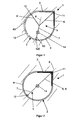
- FIG. 1 shows the application of a first embodiment of the clamping device 1 according to the invention can be introduced into an opening 2 such as window opening, which clamping device 1 a corner element 3 and two corresponding to the peripheral shape of the opening 2 arcuate side elements 4, 40, and one of the adjusting devices 5, 50 with the corner element 3 and a with the side elements 4, 40 coupled clamping device 14, wherein an actuation of a centrally arranged clamping device 14 causes an extension of at least one side of the clamping device 1, at least in the form that the side elements 4, 40 by a forced by the operation of a clamping device 14 movement of the adjusting devices 5, 50 can be applied to a side edge 13 of the opening 2.
- an opening 2 such as window opening
- clamping device 1 a corner element 3 and two corresponding to the peripheral shape of the opening 2 arcuate side elements 4, 40, and one of the adjusting devices 5, 50 with the corner element 3 and a with the side elements 4, 40 coupled clamping device 14, wherein an actuation of a centrally arranged clamping device 14 causes
- the corner element 3 is formed as a rigidly formed in the plane of extension of the jig element with two legs enclosing a right angle.
- the adjusting device 5, 50 is coupled to the corner element 3, so that the corner element 3 can be applied to two side edges 13 of the opening 2 by a movement of the adjusting devices 5, 50 forced by the actuation of the one clamping device 14.
- the adjusting devices 5, 50 are arranged in a star shape around the one clamping device 14 and at least two adjusting devices 5, 50 lying opposite one another on an adjusting shaft 8 can be actuated by the one clamping device 14.
- the introduced into the opening 2 jig 1 can be tensioned by a forced by a clamping device 14 movement of the corner element and the side member in the opening 2.
- the corner element 3 can be applied to two, at a right angle oriented portions of the side edge 13 of the opening by means of the adjusting device 5, wherein the adjusting device 5 is coupled to the corner element 3 at a Eckangriffstician 11 and the clamping device 14.
- the side elements 4, 40 to the side edge 13 of the opening 2 by means of the adjusting devices 5, 50 can be applied, wherein the adjusting devices 5, 50 are coupled to the side member 4, 40 at the side attack points 12, 120 and the tensioning device 14.
- the adjusting device 5 comprises first adjusting elements 6, 6 'and a second adjusting element 7, wherein the second adjusting element 7 with the clamping device 14 and the first adjusting elements 6, 6', one of the first adjusting elements 6, 6 'with the second adjusting element 7 and Corner 3 or the side member 4, 40 is coupled.
- the second adjusting element 7 is arranged on the adjusting axis 8.
- the first adjusting elements 6, 6 ' are arranged at an arbitrary angle to the adjusting axis 8.
- the accounts between the first adjusting elements 6, 6 'and the second adjusting element 7 is designed as a rigid node.
- the corner element 3 is designed as a rigid element.
- the corner element 3 is further designed to be stretchable in subregions adjacent to the side elements 4, 40, so that an extension of one side of the clamping device 1 can be accomplished while maintaining a bond between the side element and the corner element.
- the side elements 4, 40 comprise a first side part element and a second side part element, wherein the second side part element is slidably mounted parallel to the longitudinal extent of the first side part element, so that an extension of the side of the clamping device 1 can be produced by a displacement of the second side part element relative to the first side part element.
- the tensioning device 14 By means of the tensioning device 14, the adjusting devices 5, 50 can be actuated.
- FIG. 2 shows a view of a further first embodiment of the clamping device according to the invention, which is introduced into an opening 2 with a polygonal, a corner comprehensive cross-section.
- the embodiment shown differs from that in FIG. 1 shown embodiment in that the adjusting device 5 is coupled exclusively with the corner element 3 at the corner application point 11 and with a tensioning device 14, the adjusting device 50 with the side member 4 at the side attack point 12 and a tensioning device 14.
- the adjusting device 5 comprises only a first adjusting element 6 and a second adjusting element 7.
- the side element 4 is mounted extendable parallel to the longitudinal extent of the side member 4 of the corner element 3, so that the relevant side of the clamping device 1, on which the side member 4 extends, stretchable is.
- FIG. 3 shows a view of a second embodiment of the clamping device according to the invention can be introduced into an opening 2, which clamping device 1 three side elements 4, 40, 400, with the side elements 4, 40, 400 coupled adjusting devices 5, 50 and a coupled to the adjusting devices 5, 50 clamping device 14th an actuation of the one tensioning device 14 causes an extension of at least one side of the clamping device 1 in the mold, so that the side elements 4, 40, 400 by a forced by the operation of a tensioning device 14 movement of the adjusting devices 5, 50 to a Side edge 13 of the opening 2 can be applied, wherein the adjusting devices 5, 50 are arranged in a star shape about a clamping device 14 and at least two on a control axis 8 opposite adjusting devices 5, 50 by a clamping device 14 are actuated.
- FIG. 4 shows the view of an embodiment of the clamping device according to the invention, which is introduced into an opening 2 with a rectangular cross-section.
- the FIG. 4 embodiment shown comprises four corner elements 3, 30, 300, 3000 and four side elements 4, 40, 400, 4000.
- the adjusting devices 5, 50 used for this purpose each comprise two first adjusting elements 6, 6 ', 60, 60' and a second adjusting element 7, 70.
- the first adjusting elements 6, 6 ', 60, 60' are at the corner engaging points 11, 110, 1100 , 11000 coupled to the corner elements 3, 30, 300, 3000 and the second control elements 7, 70.
- the second adjusting elements 7, 70 are coupled to the first adjusting elements 6, 6 ', 60, 60' and the one clamping device 14.
- the lateral side elements 40, 4000 are applied by means of adjusting devices 500, 5000 to the side edge 13 of the opening 2.
- the actuators 500, 5000 are coupled at the lateral engagement points 12, 120 to the side member 40, 4000 and to the one tensioning device 14.
- the adjusting devices 5, 50, 500, 5000 are actuated.
- the adjusting devices 5, 50, 500, 5000 are arranged in a star shape around the one tensioning device.
- FIG. 5 shows a sectional view of in FIG. 4 shown embodiment.
- a surface element 15 can be seen, which extends substantially over the extension surface.
- the longitudinal axes of the adjusting devices 5, 50 include a deviating from 180 ° angle to each other.
- the surface element 15 extends in the subregions adjacent to the respective adjusting devices 5, 50 parallel to the respective adjusting device 5, 50.
- a vertical force 17, which acts on the adjusting devices 5, 50 in the region of the clamping device 14, by horizontal support forces 18 in the Side edge 13 of the opening 2 was added.
- the clamping device 1 further comprises a hinge 16, by means of which the clamping device 1 is rotatable in the opening 2 and in the position located in the opening 2 by an operation of the clamping device 14 in the opening 2 is clamped.
- FIG. 6 3 shows a view of a third embodiment of the clamping device according to the invention, insertable into an opening 2, which clamping device 1 comprises three corner elements 3, 30, 300, adjusting devices 5, 50, 500, as well as a clamping device 14 coupled to the adjusting devices 5, 50, 500 an actuation of a clamping device 14 causes an extension of at least one side of the clamping device 1, so that the corner elements 3, 30, 300 by a forced by the operation of the clamping device 14 movement of the adjusting device 5, 50, 500 can be applied to two side edges 13 of the opening 2 ,
- the adjusting devices 5, 50, 500 are arranged in a star shape around the one tensioning device 14 and at least two adjusting devices 5, 50, 500 lying opposite one of the adjusting axles 8, 80, 800 can be actuated by the tensioning device 14.
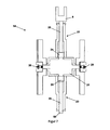
- FIG. 7 shows a sectional view of an embodiment of a clamping device 14 for use of a clamping device according to the invention, which is operable by means of compressed air.
- a valve 20 compressed air is introduced into a compressed air chamber 21 by means of a compressed air cartridge (not shown). It is arranged on both sides of the clamping device 14, a valve 20, so that the clamping device 14 is operable on both sides.
- a cartridge guide element is arranged to allow easy attachment of the compressed air cartridge.
- the tensioning device 14 further comprises two pressure cylinders 23 together with pressure piston 24 and piston rods 25. By means of pressure cylinder 23, the adjusting device 5, 50 connected to the piston rods 25 is moved away in the direction of the compressed air chamber 21.
- the adjusting devices 5, 50 are arranged on the opposite sides of the compressed air chamber 21.
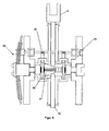
- FIG. 8 shows a sectional view of an embodiment of a clamping device 14, through which a movement of the adjusting device 5, 50 can be performed.
- the tensioning dome is moved in a direction substantially perpendicular to the movement of the adjusting device 5, 50 to be performed by means of a clamping mandrel setting device 26.
- the Spanndornstellvoretticardi 26 is to be rotated in this case, wherein a thread from a rotating movement of the Spanndomstellvorplatz 26 a linear movement of the mandrel 27 is effected.
- the tensioning dome 27 is rotated, whereby due to the conical shape of the tensioning dome 27, a linear movement of the adjusting devices 5, 50 is effected.
- a securing blade 28 serves to secure the applied movement of the tensioning dome 27.
- the locking blade 28 is coupled to the Spanndornstellvorides 26 via a gear 30.
- the securing blade 28 can be released, so that the applied movement of the adjusting device 5, 50 can be solved.
- FIG. 9 shows a sectional view of another embodiment of a clamping device 24, wherein, in contrast to the in FIG. 8 illustrated embodiment of the tensioning dome 27 undergoes a rotational and linear movement, wherein the adjusting devices 5, 50 are moved in a direction substantially perpendicular to the linear movement of the mandrel 27 direction.
Landscapes
- Engineering & Computer Science (AREA)
- Structural Engineering (AREA)
- Architecture (AREA)
- Civil Engineering (AREA)
- Clamps And Clips (AREA)
- General Engineering & Computer Science (AREA)
- Buildings Adapted To Withstand Abnormal External Influences (AREA)
- Mechanical Engineering (AREA)
- Connection Of Plates (AREA)
Description
- Diese Erfindung betrifft eine Einspannvorrichtung einspannbar in eine Öffnung, welche Einspannvorrichtung zumindest ein Eckelement, ein Seitenelement, Stellvorrichtungen und eine über eine der Stellvorrichtungen mit dem Seitenelement verbundene Spannvorrichtung zur Stellung der Seitenelemente gegen eine Seitenkante der Öffnung umfasst.
- Das Gebrauchsmuster
DE102006026366A1 beschreibt eine Einspannvorrichtung für Öffnungen in einem Mauerwerk. Die offenbarte Einspannvorrichtung besteht aus einem Wasser abhaltenden Element, welches von einem Rahmen in der Öffnung gehalten wird. Der Rahmen ist in seiner Höhe und Breite veränderbar und wird mittels Längs- und Querverspannungen gegen einen durch die Öffnung gebildeten Maueranschlag verspannt. - Die in
DE102006026366A1 beschriebene Einspannvorrichtung weist den Nachteil auf, dass diese insofern nur in einem aufwendigen Verfahren in die Öffnung des Mauerwerkes eingesetzt werden kann, zumal eine Vielzahl von Längs- und Querverspannungen einzeln betätigt werden muss. Eine Veränderung der Breite des Rahmens mittels einer Querverspannung ist aufgrund der durch die Längsverspannung aktivierten Reibung zwischen Rahmen und Maueranschlag nur schwer möglich. - In
GB2373534 GB2373534 - Die in
DE4023286 beschriebene Ausführungsform der Spannelemente als Gewindespindeln bedingt das Vorsehen eines Vorspannelementes pro als Stellvorrichtung wirkender Stange. Dies bedingt wiederum, dass eine sternförmige Anordnung der Stangen um die Vorspannvorrichtung bei einer Ausführung gemäß Offenbarung vonDE4023286 nicht möglich ist. -
FR2739132 - Die hier diskutierte Erfindung stellt sich die Aufgabe eine in eine Öffnung in einem leicht durchführbaren Verfahren einbringbare und in dieser verspannbare Einspannvorrichtung bereitzustellen. Die erfindungsgemäße Einspannvorrichtung zeichnet sich durch eine systematische Anordnung der Stellvorrichtung und Spannvorrichtung aus, wobei sich die im folgenden beschriebene systematische Anordnung ein Verspannen der Einspannvorrichtung in Öffnungen mit beliebigen, insbesondere rechteckigen und runden Querschnitten erlaubt.
- Ein Anwendungsgebiet der erfindungsgemäßen Einspannvorrichtung ist der Hochwasserschutz. Die Einspannvorrichtung wird hierzu in eine Mauerwerksöffnung als Öffnung gegebenenfalls in einer Position parallel zu einer Türe oder eines Fensters angeordnet, um die Mauerwerksöffnung wasserdicht zu verschließen.
- Die Einspannvorrichtung kann weiters in eine Öffnung eingespannt werden, um mit den die Öffnung begrenzenden Elementen ein statisches System zu bilden. Ein Beispiel einer solchen Anwendung ist die Sicherung eines Mauerwerks als Öffnung gegen Einsturz. Weiters kann die erfindungsgemäße Einspannvorrichtung in ein Stützen und Balken umfassendes Gerüst eingespannt werden, um dieses in der Ebene der erfindungsgemäßen Einspannvorrichtung auszusteifen.
- Ebenso ist eine Verwendung des erfindungsgemäßen Einspannelementes als Schalungselement möglich, welches in eine Mauerwerksöffnung oder in eine Öffnung zwischen Stützen und Balken eines Schalungsstützwerkes einspannbar ist.
- Eine erste Ausführungsform der erfindungsgemäßen Einspannvorrichtung ist in eine Öffnung einspannbar, welche Einspannvorrichtung zumindest ein Eckelement, ein Seitenelement, zumindest eine Stellvorrichtung und eine über eine Stellvorrichtung mit dem Seitenelement verbundene Spannvorrichtung zur Stellung des Seitenelementes gegen eine Seitenkante der Öffnung umfasst. Die erste erfindungsgemäße Ausführungsform der Einspannvorrichtung zeichnet sich dadurch aus, dass das zumindest eine Eckelement als eine in der Erstreckungsebene der Einspannvorrichtung biegesteif ausgebildetes Element ausgebildet ist, die eine Spannvorrichtung über die Stellvorrichtung mit dem Eckelement zur Stellung des Eckelementes gegen eine Seitenkante der Öffnung verbunden ist, wobei die mit dem Eckelement oder dem Seitenelement verbundene Stellvorrichtungen um die eine Spannvorrichtung sternförmig angeordnet sind.
- Durch die Betätigung der einen Spannvorrichtung ist das zumindest eine Eckelement und das zumindest eine Seitenelement gegen die Seitenkante der Öffnung stellbar, wodurch die in die Öffnung eingebrachte Einspannvorrichtung durch eine durch die Bewegung des zumindest einen Eckelementes und des zumindest einen Seitenelementes in der Mauerwerksöffnung einspannbar ist.
- Eine zweite Ausführungsform der erfindungsgemäßen Einspannvorrichtung ist in eine Öffnung einbringbar. Die Einspannvorrichtung umfasst zumindest drei Seitenelemente, Stellvorrichtungen, mit den Seitenelementen gekoppelte Stellvorrichtungen sowie eine mit zumindest einer der Stellvorrichtungen gekoppelte Spannvorrichtung zur Stellung der Seitenelemente gegen jeweils eine Seitenkante der Öffnung. Die erfindungsgemäße zweite Einspannvorrichtung zeichnet sich dadurch aus, dass die Stellvorrichtungen um die eine Spannvorrichtung im wesentlichen sternförmig angeordnet sind.
- Durch die Betätigung der einen Spannvorrichtung sind die zumindest drei Seitenelemente gegen die Seitenkante der Öffnung stellbar, wodurch die in die Öffnung eingebrachte Einspannvorrichtung durch eine durch die Bewegung der zumindest drei Eckelemente erzwungene Vergrößerung der flächenmäßigen Erstreckung der Einspannvorrichtung in der Öffnung einspannbar ist.
- Eine dritte Ausführungsform der erfindungsgemäßen Einspannvorrichtung ist einspannbar in eine Öffnung und umfasst zumindest drei Eckelemente, Stellvorrichtungen, eine über Stellvorrichtungen mit den Eckelementen verbundene Spannvorrichtung. Die erfindungsgemäße dritte Ausführungsform zeichnet sich dadurch aus, dass die zumindest drei Eckelemente biegesteif ausgebildete Elemente sind, die eine Spannvorrichtung über eine der Stellvorrichtungen mit zumindest einem Eckelement verbunden ist, wobei die Stellvorrichtungen um die eine Spannvorrichtung im wesentlichen sternförmig angeordnet sind.
- Durch die Betätigung der einen Spannvorrichtung sind die zumindest drei Eckelemente gegen die Seitenkante der Öffnung stellbar, wodurch die in die Öffnung eingebrachte Einspannvorrichtung durch eine durch die Bewegung der Eckelemente erzwungene flächenmäßige Vergrößerung der Einspannvorrichtung in der Öffnung einspannbar ist.
- Vorzugsweise sind die Eckelemente und gegebenenfalls die Seitenelemente oder die Stellelemente linear verschiebbar gelagert. Die Orientierung der linear verschiebbaren Lagerung ist im wesentlichen parallel zu der Anordnung eines Stellelementes orientiert.
- Durch das Anpressen zumindest eines Eckelementes an die Seitenkanten der Öffnung bei gleichzeitigem Anpressen eines weiteren Eckelementes oder eines Seitenelementes an die Seitenkante der Öffnung wird ein Verspreizen der Einspannvorrichtung bewirkt.
- Die hier gegebenen Angaben bezüglich einer Anordnung der Stellelemente beziehen sich auf eine Anordnung des Stellelementes hinsichtlich ihrer Wirkungsachsen.
- Umfasst die Einspannvorrichtung zwei Stellelemente, so wird eine sternförmige Anordnung durch die zwei Stellelemente so gebildet, dass die Stellelemente sich entlang einer Achse erstrecken.
- Das Stellelement ist beziehungsweise die Stellelemente sind im Zentrumspunkt der sternförmigen Stellvorrichtungen, wobei die zum Stellen der Stellvorrichtungen aufzuwendenden Kräfte im Zentrumspunkt im Gleichgewicht stehen.
- Eine Seitenkante und eine weitere Seitenkante der Öffnung können eine Ecke der Öffnung ausbilden, in welche ein Eckelement anlegbar ist. Die eine Seitenkante muss keinesfalls zu der weiteren Seitenkante rechtwinkelig, sondern kann in einem beliebigen Winkel angeordnet sein. Eine Seitenkante und eine weitere Seitenkante können einen positiven oder einen negativen Winkel bilden, an welchen Winkel das Eckelement anlegbar ist. Ebenso kann eine Seitenkante und eine weitere Seitenkante an polygonal verlaufenden Übergang aufweisen.
- Ein Eckelement unterscheidet sich von einem Seitenelement dadurch, dass das Eckelement an zwei Seitenkanten der Öffnung angelegt wird. Ein Verschieben des Eckelementes im Zuge der Anlegung des Eckelementes an die Seitenkanten in eine Richtung im wesentlichen parallel zu einer der Seitenkanten der Öffnung ist nicht möglich.
- Ein Eckelement kann aus zwei, in einem Winkel zueinander stehenden Schenkelelementen bestehen, welche biegesteif verbunden sind.
- In einer bevorzugten Anordnung sind die Stellvorrichtungen entlang einer den zentralen Punkt durchlaufenden Achse angeordnet. Bei einer solchen Anordnung sind die Druckkräfte, welche durch die Spannvorrichtung auf die Stellvorrichtung, in weiterer Folge durch das Eck- oder Seitenelement auf eine Seitenkante der Öffnung aufgebracht werden, entgegengesetzt gleich.
- Wird die Erstreckungsfläche der Einspannvorrichtung in nur einen Teilbereich unterteilt, so weist die Einspannvorrichtung vorzugsweise nur eine Spannvorrichtung auf. Wird die Erstreckungsfläche der Einspannvorrichtung in nur zwei oder mehrere Teilbereiche unterteilt, so weist die Einspannvorrichtung vorzugsweise zwei oder mehrere Spannvorrichtung auf.
- Ein Teilbereich der Erstreckungsfläche kann mit einem weiteren Teilbereich der Erstreckungsfläche überschneidend angeordnet sein.
- Die Spannvorrichtung bewirkt eine Druckausübung und/oder eine Bewegung der Stellvorrichtung in Richtung einer Seitenkante der Öffnung. Durch den mittels der Spannvorrichtung über die Stellvorrichtung, Eck- und Seitenelement aufgebrachten Druck ist die Einspannvorrichtung in der Öffnung einspannbar.
- Die Spannvorrichtung kann mechanische und/oder hydraulische Komponenten umfassen, welche eine solche Druckausübung bewirken. Die Spannvorrichtung kann weiters eine Arretierungsvorrichtung umfassen, durch welche eine Abminderung des ausgeübten Drucks, in weiterer Folge ein Lösen der Spannvorrichtung unterbunden wird.
- Eine Ausführungsform der erfindungsgemäßen Einspannvorrichtung kann sich dadurch auszeichnen, dass die Stellvorrichtung erste Stellelemente und ein zweites Stellelement umfasst, wobei das zweite Stellelement mit der Spannvorrichtung und den ersten Stellelementen, zumindest eines der ersten Stellelemente mit dem zweiten Stellelement und dem Eckelement oder dem Seitenelement gekoppelt ist, wobei zumindest das zweite Stellelement auf der Stellachse angeordnet ist und die ersten Stellelemente in einem beliebigen Winkel zu der Stellachse angeordnet sind.
- Es sind zwei erste Stellelemente mit dem Eckelement oder dem Seitenelement verbunden. Durch diese Anordnung kann eine bessere Aufteilung der durch die Stellvorrichtung aufgebrachten Druckkräfte auf die Seitenkante der Öffnung bewirkt werden. Vorzugsweise sind die Eckelemente und/oder die Seitenelemente so ausgebildet, dass die aufgebrachten Druckkräfte optimal eingeleitet werden können. Das Eckelement und/oder das Seitenelement weist beispielsweise im Kopplungspunkt mit dem ersten Stellelement eine höhere Biegesteifigkeit auf.
- Vorzugsweise sind die ersten Stellelemente in einem definierten Winkel zu der Stellachse angeordnet, so dass das zweite Stellelement nicht durch Querkräfte belastet ist. Im Regelfall sind jeweils zwei der ersten Stellelemente spiegelgleich, um einen gleichen Winkelbetrag von der Stellachse abweichend angeordnet.
- Das Eckelement kann in zumindest Teilbereichen flexibel ausgeführt sein, sodass das Eckelement in seiner Form an die Seitenkante anpassbar ist und/oder eine Streckung einer Seite der Einspannvorrichtung bewerkstelligbar ist.
- Das Eckelement kann eine Dichtung umfassen, welche so angeordnet ist, dass durch die Einspannvorrichtung ein luft- oder wasserdichtes Abschließen der Öffnung im Teilbereich eines Eckelementes herstellbar ist.
- Die Dichtung kann Dichtungsteilbereiche umfassen, welche durch ein Fluid verfüllbar sind. Vorzugsweise stehen die Dichtungsteilbereiche mit einer hydraulischen Spannvorrichtung in Fluidkommunikation, sodass durch die Betätigung der Spannvorrichtung ein Einspann der Einspannvorrichtung in der Öffnung, weiters ein Verfüllen der Dichtungsteilbereiche bewirkbar ist.
- Bei einer unverschieblichen Verbindung von Eckelement und Seitenelement kann eine Streckung der Seite auch durch eine Dehnung eines Schenkels des Eckelementes bewirkt werden.
- Das Seitenelement kann parallel zu der Längsachse aus dem Eckelement ausziehbar ausgeführt sein, sodass die betreffende Seite der Einspannvorrichtung, an welcher sich das Seitenelement erstreckt, streckbar ist.
- Die Dichtung kann als ein den durch die Eckelemente und/oder Seitenelemente gebildeten Umfang der Einspannvorrichtung umschließende dehnbares Band ausgebildet sein, dessen Dehnungskraft einer Streckung einer Seite der Einspannvorrichtung entgegenwirkt.
- Ebenso kann das Seitenelement ein erstes Seitenteilelement und ein zweites Seitenteilelement umfassen, wobei das zweite Seitenteilelement parallel zu der Längsachse des ersten Seitenteilelementes verschiebbar gelagert ist, wobei durch ein Verschieben des zweiten Seitenteilelementes relativ zum ersten Seitenteilelement eine Verlängerung der Seite der Einspannvorrichtung herstellbar ist.
- Die angeführten Ausführungsformen, welche eine Streckung eines Seitenelementes erlauben, können im Rahmen dieser Erfindung kombiniert werden.
- Das Seitenelement kann in zumindest Teilbereichen flexibel ausgeführt sein, sodass das Seitenelement in seiner Form an die Seitenkante anpassbar ist.
- Das Seitenelement kann beispielsweise eine Dichtung umfassen, mittels welcher eine dichte Verschließung der Öffnung im Bereich des Seitenelementes durch die Einspannvorrichtung herstellbar ist. Vorzugsweise ist eine dehnbare Dichtung um die Umfangskante der Erstreckungsfläche vorgesehen. Die Dichtung in jenen Teilbereichen ist um das Maß dehnbar, um welches Maß das Seitenelement gestreckt wird.
- Vorzugsweise sind mittels einer Spannvorrichtung mehrere Stellvorrichtungen betätigbar.
- Die Spannvorrichtung kann so ausgebildet sein, dass ein Spannvorgang, welcher durch die Betätigung der Spannvorrichtung ausgelöst wird, mehrere Hauptspannvorgänge und Nebenspannvorgänge umfasst. Beispielsweise werden durch die Hauptspannvorgänge die Eckelemente an die Seitenkanten, durch die Nebenspannvorgänge die Seitenelemente and die Seitenkanten angelegt.
- Die Einspannvorrichtung kann ein Flächenelement umfassen, welches Flächenelement sich zumindest über Teilbereich der Erstreckungsfläche erstreckt und an dem Eckelement und/oder an dem Seitenelement befestigbar und gegebenenfalls an den Stellvorrichtungen lagerbar ist.
- Die Einspannvorrichtung kann zwei Flächenelemente umfassen, welche so angeordnet sind, dass zumindest die Stellvorrichtung im wesentlichen zwischen den Flächenelementen angeordnet ist.
- Ein Flächenelement kann mehrere Flächenteilelemente umfassen, wenn einander überlappend angeordnet sind. Die Flächenteilelement sind parallel zu Ihrer Erstreckungsebene verschiebbar, sodass durch die Verschiebung der Flächenteilelemente eine Vergrößerung oder eine Verkleinerung des Flächenelementes herstellbar ist.
- Das Flächenelement kann dehnbar sein.
- Das Flächenelement kann eine gekrümmte Form oder eine Form einer Oberfläche einer prismenartigen oder pyramidenartigen Geometrie aufweisen, wobei eine Vergrößerung der Erstreckung des Flächenelementes durch eine Veränderung der gekrümmten Form oder der pyramidenartigen Form bewerkstelligbar ist.
- Die Stellvorrichtung ist in einer möglichen Ausführungsform der erfindungsgemäßen Einspannvorrichtung in einem Winkel zu einer Ebene angeordnet ist, welche Ebene durch die Eckelemente und/oder durch die Seitenelemente definiert ist, sodass eine auf eine Stellvorrichtung wirkende Kraft, welche Kraft im wesentlichen rechtwinkelig auf die Ebene gerichtet ist, durch eine Druckbelastung der Stellvorrichtung in die Seitenkante der Öffnung ableitbar ist.
- Die Stellelemente können mittels einer Justiervorrichtung in ihrer Länge einstellbar sein, sodass die Erstreckungsfläche sich von der Öffnung um ein Maß unterscheidet, um welches Maß die Erstreckungsfläche mittels der Spannvorrichtung erweiterbar ist.
- Durch die Anordnung von Justierelementen zur Einstellung der Länge der Stellelemente kann die Einspannvorrichtung besser an die Form der Öffnung anpassbar sein.
- Wie eingangs angeführt, kann die Einspannvorrichtung zur Verschließung von Mauerwerksdurchbrüchen verwendet werden. Eine solche Verschließung kann beispielsweise eine Maßnahme eines Hochwasserschutzes sein.
- Die Einspannvorrichtung kann ein Teil eines Rahmens sein, welcher in die Öffnung einspannbar ist. Ein solcher Rahmen kann beispielsweise ein Rahmen eines Fensters oder einer Türe sein, welcher Rahmen mittels der erfindungsgemäßen Einspannvorrichtung im Mauerwerksdurchbruch verspreizt wird.
- Eine weitere Möglichkeit einer Anwendung der erfindungsgemäßen Einspannvorrichtung liegt im Bereich von einbruchshemmenden Schließsystemen für Türen oder Fenstern.
- Die Einspannvorrichtung ist hierzu in die beziehungsweise aus der Öffnung drehbar und/oder verschiebbar gelagert.
-
Figur 1 zeigt eine Ansicht einer ersten Ausführungsform der erfindungsgemäßen Einspannvorrichtung, welche in eine Öffnung mit einem polygonalen, eine Ecke umfassenden Querschnitt eingebracht ist. -
Figur 2 zeigt eine Ansicht einer weiteren ersten Ausführungsform der erfindungsgemäßen Einspannvorrichtung, welche in eine Öffnung mit einen polygonalen, eine Ecke umfassenden Querschnitt eingebracht ist. -
Figur 3 zeigt eine Ansicht einer zweiten Ausführungsform der erfindungsgemäßen Einspannvorrichtung, welche in eine Öffnung mit einem kreisförmigen Querschnitt eingebracht ist. -
Figur 4 zeigt eine Ansicht einer weiteren ersten Ausführungsform der erfindungsgemäßen Einspannvorrichtung, welche in eine Öffnung mit einem rechteckigen Querschnitt eingebracht ist. -
Figur 5 zeigt ein Schnittbild der inFigur 4 gezeigten Ausführungsform. -
Figur 6 zeigt eine Ansicht einer dritten Ausführungsform. -
Figur 1 zeigt die Anwendung einer ersten Ausführungsform der erfindungsgemäßen Einspannvorrichtung 1 einbringbar in eine Öffnung 2 wie zum Beispiel Fensteröffnung, welche Einspannvorrichtung 1 ein Eckelement 3 und zwei entsprechend der Umfangsform der Öffnung 2 bogenförmig ausgebildete Seitenelemente 4, 40, sowie eine über die Stellvorrichtungen 5, 50 mit dem Eckelement 3 und eine mit den Seitenelementen 4, 40 gekoppelte Spannvorrichtung 14 umfasst, wobei eine Betätigung der einen zentral angeordneten Spannvorrichtung 14 eine Streckung zumindest einer Seite der Einspannvorrichtung 1 zumindest in der Form bewirkt, dass die Seitenelemente 4, 40 durch eine durch die Betätigung der einen Spannvorrichtung 14 erzwungene Bewegung der Stellvorrichtungen 5, 50 an eine Seitenkante 13 der Öffnung 2 anlegbar ist. Durch das Anlegen der Seitenkanten 4,40 und des Eckelemente 3 an die Seitenkante 13 der Öffnung wird ein Verspannen der Einspannvorrichtung 1 in der Öffnung bewerkstelligt. Das Eckelement 3 ist als ein in der Erstreckungsebene der Einspannvorrichtung biegesteif ausgebildetes Element mit zwei einen rechten Winkel einschließende Schenkel ausgebildet. Die Stellvorrichtung 5, 50 ist mit dem Eckelement 3 gekoppelt, sodass das Eckelement 3 durch eine durch die Betätigung der einen Spannvorrichtung 14 erzwungene Bewegung der Stellvorrichtungen 5, 50 an zwei Seitenkanten 13 der Öffnung 2 anlegbar ist. Die Stellvorrichtungen 5, 50 sind um die eine Spannvorrichtung 14 sternförmig angeordnet und zumindest zwei auf einer Stellachse 8 gegenüber liegende Stellvorrichtungen 5, 50 sind durch die eine Spannvorrichtung 14 betätigbar. Die in die Öffnung 2 eingebrachte Einspannvorrichtung 1 ist durch eine durch die eine Spannvorrichtung 14 erzwungene Bewegung des Eckelementes und des Seitenelementes in der Öffnung 2 spannbar. - Das Eckelement 3 ist an zwei, in einem rechten Winkel zueinander orientierte Teilbereiche der Seitenkante 13 der Öffnung mittels der Stellvorrichtung 5 anlegbar, wobei die Stellvorrichtung 5 mit dem Eckelement 3 an einem Eckangriffspunkt 11 und der Spannvorrichtung 14 gekoppelt ist. In dazu analoger Weise sind die Seitenelemente 4, 40 an die Seitenkante 13 der Öffnung 2 mittels der Stellvorrichtungen 5, 50 anlegbar, wobei die Stellvorrichtungen 5, 50 mit dem Seitenelement 4, 40 an den Seitenangriffspunkten 12, 120 und der Spannvorrichtung 14 gekoppelt sind. Die Stellvorrichtung 5 umfasst erste Stellelemente 6, 6' und ein zweites Stellelement 7, wobei das zweite Stellelement 7 mit der Spannvorrichtung 14 und den ersten Stellelementen 6, 6', jeweils eines der ersten Stellelemente 6, 6' mit dem zweiten Stellelement 7 und dem Eckelement 3 oder dem Seitenelement 4, 40 gekoppelt ist. Das zweite Stellelement 7 ist auf der Stellachse 8 angeordnet. Die ersten Stellelemente 6, 6' sind in einem beliebigen Winkel zu der Stellachse 8 angeordnet. Der Konten zwischen ersten Stellelementen 6, 6' und dem zweiten Stellelement 7 ist als biegesteifer Knoten ausgebildet.
- Das Eckelement 3 ist als ein starres Element ausgeführt. Das Eckelement 3 ist weiters in Teilbereichen benachbart zu den Seitenelementen 4, 40 dehnbar ausgeführt, sodass eine Streckung einer Seite der Einspannvorrichtung 1 unter Beibehaltung eines Verbundes zwischen Seitenelement und Eckelement bewerkstellbar ist.
- Die Seitenelemente 4, 40 umfassen ein erstes Seitenteilelement und ein zweites Seitenteilelement, wobei das zweite Seitenteilelement parallel zu der Längserstreckungdes ersten Seitenteilelementes verschiebbar gelagert ist, sodass durch ein Verschieben des zweiten Seitenteilelementes relativ zum ersten Seitenteilelement eine Verlängerung der Seite der Einspannvorrichtung 1 herstellbar ist.
- Mittels der Spannvorrichtung 14 sind die Stellvorrichtungen 5, 50 betätigbar.
-
Figur 2 zeigt eine Ansicht einer weiteren ersten Ausführungsform der erfindungsgemäßen Einspannvorrichtung, welche in eine Öffnung 2 mit einen polygonalen, eine Ecke umfassenden Querschnitt eingebracht ist. Die inFigur 2 gezeigte Ausführungsform unterscheidet sich von der inFigur 1 gezeigten Ausführungsform dadurch, dass die Stellvorrichtung 5 ausschließlich mit dem Eckelement 3 am Eckangriffspunkt 11 und mit der einen Spannvorrichtung 14, die Stellvorrichtung 50 mit dem Seitenelement 4 am Seitenangriffspunkt 12 und der einen Spannvorrichtung 14 gekoppelt ist. Die Stellvorrichtung 5 umfasst nur ein erstes Stellelement 6 und ein zweites Stellelement 7. Das Seitenelement 4 ist parallel zu der Längserstreckung des Seitenelementes 4 aus dem Eckelement 3 ausziehbar gelagert, sodass die betreffende Seite der Einspannvorrichtung 1, an welcher sich das Seitenelement 4 erstreckt, streckbar ist. -
Figur 3 zeigt eine Ansicht einer zweiten Ausführungsform der erfindungsgemäßen Einspannvorrichtung einbringbar in eine Öffnung 2, welche Einspannvorrichtung 1 drei Seitenelemente 4, 40, 400, mit den Seitenelementen 4, 40, 400 gekoppelte Stellvorrichtungen 5, 50 sowie eine mit den Stellvorrichtungen 5, 50 gekoppelte Spannvorrichtung 14 umfasst, wobei eine Betätigung der einen Spannvorrichtung 14 eine Streckung zumindest einer Seite der Einspannvorrichtung 1 in der Form bewirkt, so dass die Seitenelemente 4, 40, 400 durch eine durch die Betätigung der einen Spannvorrichtung 14 erzwungene Bewegung der Stellvorrichtungen 5, 50 an eine Seitenkante 13 der Öffnung 2 anlegbar sind, wobei die Stellvorrichtungen 5, 50 um die eine Spannvorrichtung 14 sternförmig angeordnet sind und zumindest zwei auf einer Stellachse 8 gegenüber liegende Stellvorrichtungen 5, 50 durch die eine Spannvorrichtung 14 betätigbar sind. -
Figur 4 zeigt die Ansicht einer Ausführungsform der erfindungsgemäßen Einspannvorrichtung, welche in eine Öffnung 2 mit einem rechteckigen Querschnitt eingebracht ist. Die inFigur 4 gezeigte Ausführungsform umfasst vier Eckelemente 3, 30, 300, 3000 und vier Seitenelemente 4, 40, 400, 4000. Es werden jeweils zwei der vier Eckelemente 4, 40, 400, 4000 durch jeweils eine Stellvorrichtung 5, 50 an die Ecken der Öffnung 2 angelegt. - Die hierzu verwendeten Stellvorrichtungen 5, 50 umfassen jeweils zwei erste Stellelemente 6, 6', 60, 60' und ein zweites Stellelement 7, 70. Die ersten Stellelemente 6, 6', 60, 60' sind an den Eckangriffspunkten 11, 110, 1100, 11000 mit den Eckelementen 3, 30, 300, 3000 und den zweiten Stellelementen 7, 70 gekoppelt. Die zweiten Stellelemente 7, 70 sind mit den ersten Stellelementen 6, 6', 60, 60' und der einen Spannvorrichtung 14 gekoppelt.
- Die seitlichen Seitenelemente 40, 4000 werden mittels Stellvorrichtungen 500, 5000 an die Seitenkante 13 der Öffnung 2 angelegt. Die Stellvorrichtungen 500, 5000 sind an den Seitenangriffpunkten 12, 120 mit dem Seitenelement 40, 4000 und mit der einen Spannvorrichtung 14 gekoppelt.
- Mittels der Spannvorrichtung 14 werden die Stellvorrichtungen 5, 50, 500, 5000 betätigt. Die Stellvorrichtungen 5, 50, 500, 5000 sind sternförmig um die eine Spannvorrichtung angeordnet.
-
Figur 5 zeigt ein Schnittbild der inFigur 4 gezeigten Ausführungsform. Es ist hierbei ein Flächenelement 15 zu sehen, welches sich in Wesentlichen über die Streckungsfläche erstreckt. Die Längsachsen der Stellvorrichtungen 5, 50 schließen einen von 180° abweichenden Winkel zueinander ein. Das Flächenelement 15 verläuft in den Teilbereichen benachbart zu den jeweiligen Stellvorrichtungen 5, 50 parallel zu der jeweiligen Stellvorrichtung 5, 50. Eine vertikale Kraft 17, welche auf die Stellvorrichtungen 5, 50 im Bereich der Spannvorrichtung 14 wirkt, wird durch horizontale Auflagerkräfte 18 in der Seitenkante 13 der Öffnung 2 aufgenommen. - Die Einspannvorrichtung 1 umfasst weiters ein Scharnier 16, mittels welchem die Einspannvorrichtung 1 in die Öffnung 2 drehbar ist und in der in der Öffnung 2 gelegenen Stellung durch eine Betätigung der Spannvorrichtung 14 in der Öffnung 2 verspannbar ist.
-
Figur 6 zeigt eine Ansicht einer dritten Ausführungsform der erfindungsgemäßen Einspannvorrichtung, einbringbar in eine Öffnung 2, welche Einspannvorrichtung 1 drei Eckelemente 3, 30, 300, Stellvorrichtungen 5, 50, 500, sowie eine mit den Stellvorrichtungen 5, 50, 500 gekoppelte Spannvorrichtung 14 umfasst, wobei eine Betätigung der einen Spannvorrichtung 14 eine Streckung zumindest einer Seite der Einspannvorrichtung 1 bewirkt, sodass die Eckelemente 3, 30, 300 durch eine durch die Betätigung der Spannvorrichtung 14 erzwungene Bewegung der Stellvorrichtung 5, 50, 500 an zwei Seitenkanten 13 der Öffnung 2 anlegbar ist. Die Stellvorrichtungen 5, 50, 500 sind um die eine Spannvorrichtung 14 sternförmig angeordnet und zumindest zwei auf einer der Stellachsen 8, 80, 800 gegenüber liegende Stellvorrichtungen 5, 50, 500 durch die eine Spannvorrichtung 14 betätigbar. -
Figur 7 zeigt ein Schnittbild einer Ausführungsform einer Spannvorrichtung 14 zur Verwendung ein einer erfindungsgemäßen Einspannvorrichtung, welche mittels Druckluft betreibbar ist. Über ein Ventil 20 wird mittels einer Druckluftkartusche (nicht abgebildet) Druckluft in eine Druckluftkammer 21 eingebracht. Es ist an beiden Seiten der Spannvorrichtung 14 ein Ventil 20 angeordnet, sodass die Spannvorrichtung 14 beidseitig bedienbar ist. Im Bereich des Ventils 20 ist ein Kartuschenführungselement angeordnet, um ein leichtes Ansetzen der Druckluftkartusche zu ermöglichen. Die Spannvorrichtung 14 umfasst weiters zwei Druckzylinder 23 samt Druckkolben 24 und Kolbenstangen 25. Mittels Druckzylinder 23 wird die an den Kolbenstangen 25 angeschlossene Stellvorrichtung 5, 50 in Richtung von der Druckluftkammer 21 weg bewegt. Die Stellvorrichtungen 5, 50 sind an den gegenüberliegenden Seiten der Druckluftkammer 21 angeordnet. -
Figur 8 zeigt ein Schnittbild einer Ausführungsform einer Spannvorrichtung 14, durch welche eine Bewegung der Stellvorrichtung 5, 50 durchgeführt werden kann. Es wird hierbei mittels einer Spanndornstellvorrichtung 26 der Spanndom in eine Richtung im wesentlichen rechtwinklig zu der durchzuführenden Bewegung der Stellvorrichtung 5, 50 bewegt. Die Spanndornstellvorrichtung 26 ist hierbei zu drehen, wobei durch einen Gewindegang aus einer drehenden Bewegung der Spanndomstellvorrichtung 26 eine lineare Bewegung des Spanndoms 27 bewirkt wird. Der Spanndom 27 wird gedreht, wobei aufgrund der konischen Form des Spanndoms 27 eine lineare Bewegung der Stellvorrichtungen 5, 50 bewirkt wird. Ein Sicherungsblatt 28 dient zur Sicherung der aufgebrachten Bewegung des Spanndoms 27. Das Sicherungsblatt 28 ist mit der Spanndornstellvorrichtung 26 über ein Zahnrad 30 gekoppelt. Mittels einer Sicherungsvorrichtung 29 kann das Sicherungsblatt 28 gelöst werden, sodass die aufgebrachte Bewegung der Stellvorrichtung 5, 50 gelöst werden kann. -
Figur 9 zeigt ein Schnittbild einer weiteren Ausführungsform einer Spannvorrichtung 24, wobei im Unterschied zu der inFigur 8 dargestellten Ausführungsform der Spanndom 27 einer drehenden und linearen Bewegung unterliegt, wobei die Stellvorrichtungen 5, 50 in einer im wesentlichen rechtwinklig zu der linearen Bewegung des Spanndorns 27 Richtung bewegt werden.
Claims (12)
- Einspannvorrichtung (1) einspannbar in eine Öffnung (2), welche Einspannvorrichtung (1) zumindest ein Eckelement (3, 30, 300, 3000), ein Seitenelement (4, 40, 400, 4000), zumindest eine Stellvorrichtung (5, 50, 500, 5000) und eine über die Stellvorrichtung (5, 50, 500, 5000) mit dem Seitenelement (4, 40, 400, 4000) verbundene Spannvorrichtung (14) zur Stellung des Seitenelementes (4, 40, 400, 4000) gegen eine Seitenkante der Öffnung (2) umfasst,
dadurch gekennzeichnet, dass
das zumindest eine Eckelement (3, 30, 300, 3000) als ein in der Erstreckungsebene der Einspannvorrichtung (1) biegesteif ausgebildetes Element ausgebildet ist,
die Spannvorrichtung (14) über die Stellvorrichtung (5, 50, 500, 5000) mit dem Eckelement (3, 30, 300, 3000) zur Stellung des Eckelementes (3, 30, 300, 3000) gegen eine Seitenkante der Öffnung (2) verbunden ist,
wobei die mit dem Eckelement (3, 30, 300, 3000) oder dem Seitenelement (4, 40, 400, 4000) verbundenen Stellvorrichtungen (5, 50, 500, 5000) um die eine Spannvorrichtung (14) sternförmig angeordnet sind. - Einspannvorrichtung (1) einspannbar in eine Öffnung (2), welche Einspannvorrichtung (1) zumindest drei Seitenelemente (4, 40, 400, 4000), Stellvorrichtungen (5, 50, 500, 5000), eine mit den Seitenelementen (4, 40, 400, 4000) über Stellvorrichtungen (5, 50, 500, 5000) gekoppelte Spannvorrichtung (14) zur Stellung der Seitenelemente (4, 40, 400, 4000) gegen eine Seitenkante der Öffnung (2) umfasst, dadurch gekennzeichnet, dass
die mit den Seitenelementen (4, 40, 400, 4000) verbundenen Stellvorrichtungen (5, 50) um die eine Spannvorrichtung (14) sternförmig angeordnet sind. - Einspannvorrichtung (1) einspannbar in eine Öffnung (2), welche Einspannvorrichtung (1) zumindest drei Eckelemente (3, 30, 300, 3000), Stellvorrichtungen (5, 50, 500, 5000) eine über die Stellvorrichtungen (5, 50, 500, 5000) mit den Eckelementen (3, 30, 300, 3000) verbundene Spannvorrichtung (14) umfasst, dadurch gekennzeichnet, dass
die zumindest drei Eckelemente (3, 30, 300, 3000) als in der Erstreckungsebene der Einspannvorrichtung (1) biegesteif ausgebildete Elemente ausgebildet sind,
die eine Spannvorrichtung (14) über eine der Stellvorrichtungen (5, 50, 500, 5000) mit zumindest einem Eckelement (3, 30, 300, 3000) zur Stellung der Eckelemente (3, 30, 300, 3000) gegen eine Seitenkante der Öffnung (2) verbunden ist,
wobei die Stellvorrichtungen (5, 50) um die eine Spannvorrichtung (14) sternförmig angeordnet sind. - Einspannvorrichtung nach einem der Ansprüche 1-3, dadurch gekennzeichnet, dass die Stellvorrichtung (5, 50) erste Stellelemente (6, 6', 60, 60') und ein zweites Stellelement (7, 70) umfasst, wobei das zweite Stellelement (7, 70) mit der Spannvorrichtung (14) und den ersten Stellelementen (6, 6', 60, 60'), zumindest eines der ersten Stellelemente (6, 6', 60, 60') mit dem zweiten Stellelement (7, 70) und dem Eckelement (3, 30, 300, 3000) oder dem Seitenelement (4, 40, 400, 4000) gekoppelt ist, wobei zumindest das zweite Stellelement (7, 70) auf auf der Stellachse (8) angeordnet ist und die ersten Stellelemente (6, 6', 60, 60') in einem beliebigen Winkel zu der Stellachse (8) angeordnet sind.
- Einspannvorrichtung (1) nach einem der Ansprüche 1-4, dadurch gekennzeichnet, dass das Eckelement (3, 30, 300, 3000) in Teilbereichen flexibel ausgeführt ist.
- Einspannvorrichtung (1) nach einem der Ansprüche 1-5, dadurch gekennzeichnet, dass das Seitenelement (4, 40, 400, 4000) parallel zu der Längsachse des Seitenelementes (4, 40, 400, 4000) aus dem Eckelement (3, 30, 300, 3000) ausziehbar ausgeführt ist.
- Einspannvorrichtung (1) nach einem der Ansprüche 1-6, dadurch gekennzeichnet, dass das Seitenelement (4, 40, 400, 4000) ein erstes Seitenteilelement und ein zweites Seitenteilelement umfasst, wobei das zweite Seitenteilelement parallel zu der Längsachse des ersten Seitenelementes verschiebbar gelagert ist.
- Einspannvorrichtung (1) nach einem der Ansprüche 1-7, dadurch gekennzeichnet, dass das Seitenelement (4, 40, 400, 4000) in zumindest Teilbereichen flexibel ausgeführt ist.
- Einspannvorrichtung (1) nach einem der Ansprüche 1-8, dadurch gekennzeichnet, dass die Einspannvorrichtung (1) ein Flächenelement (15) umfasst, welches Flächenelement (15) eine gekrümmte Form oder die Form einer Oberfläche einer prismenartigen oder pyramidenartigen Geometrie aufweist.
- Einspannvorrichtung (1) nach einem der Ansprüche 1-9, dadurch gekennzeichnet, dass die Stellvorrichtung (5, 50) in einem Winkel zu einer Ebene angeordnet ist, welche Ebene durch die Eckelemente (3, 30, 300, 3000) und/oder durch die Seitenelemente (4, 40, 400, 4000) definiert ist.
- Einspannvorrichtung (1) nach einem der Ansprüche 1-9, dadurch gekennzeichnet, dass die Stellelemente (6, 6', 60, 60', 7, 7', 70, 70') mittels einer Justiervorrichtung in ihrer Länge einstellbar sind.
- Einspannvorrichtung nach einem der Ansprüche 1-10, dadurch gekennzeichnet, dass die Einspannvorrichtung (1) verschieblich oder drehbar gelagert ist.
Applications Claiming Priority (2)
| Application Number | Priority Date | Filing Date | Title |
|---|---|---|---|
| AT0130210A AT509602B1 (de) | 2010-08-04 | 2010-08-04 | Einspannelement für mauerdurchbruch |
| PCT/AT2011/000333 WO2012016265A2 (de) | 2010-08-04 | 2011-08-03 | Einspannvorrichtung |
Publications (2)
| Publication Number | Publication Date |
|---|---|
| EP2601371A2 EP2601371A2 (de) | 2013-06-12 |
| EP2601371B1 true EP2601371B1 (de) | 2014-12-03 |
Family
ID=44650725
Family Applications (1)
| Application Number | Title | Priority Date | Filing Date |
|---|---|---|---|
| EP11757527.4A Active EP2601371B1 (de) | 2010-08-04 | 2011-08-03 | Einspannvorrichtung |
Country Status (6)
| Country | Link |
|---|---|
| US (1) | US20130129415A1 (de) |
| EP (1) | EP2601371B1 (de) |
| CN (1) | CN103097639A (de) |
| AT (1) | AT509602B1 (de) |
| CA (1) | CA2807238A1 (de) |
| WO (1) | WO2012016265A2 (de) |
Families Citing this family (1)
| Publication number | Priority date | Publication date | Assignee | Title |
|---|---|---|---|---|
| ES2551282B1 (es) * | 2014-05-15 | 2016-09-08 | Iván VICENTE SÁNCHEZ | Sistema de sellado para huecos y puertas de edificaciones que evita o minimiza los efectos de las inundaciones |
Family Cites Families (15)
| Publication number | Priority date | Publication date | Assignee | Title |
|---|---|---|---|---|
| US4578854A (en) * | 1985-02-04 | 1986-04-01 | John Demeglio | Wall repair device and method |
| US5446996A (en) * | 1989-06-29 | 1995-09-05 | Lamont; Tim | Portable security grill apparatus |
| DE4023286A1 (de) * | 1990-07-21 | 1992-01-23 | Dieter Buss | Abdichtrahmen zum verschliessen von oeffnungen |
| US5673883A (en) * | 1995-02-03 | 1997-10-07 | Figueroa, Jr.; Oscar E. | Bar device for installing a protective sheet over a window |
| FR2739132A1 (fr) * | 1995-09-25 | 1997-03-28 | Lechenault Eugene Georges | Materiel de protection et d'etancheite au ras du sol contre les inondations |
| GB2339822B (en) * | 1996-03-11 | 2000-09-20 | Vacant Property Security Ltd | Security closure |
| US5943832A (en) * | 1996-10-02 | 1999-08-31 | Russell; James E. | Flood or storm resistant barriers for doorways or window opening |
| GB2340165A (en) * | 1998-08-05 | 2000-02-16 | John Ian Rhys Harrison | Expandable flood barrier |
| GB2369391A (en) * | 2000-11-23 | 2002-05-29 | Upton Solutions | Flood barrier |
| GB2373534A (en) * | 2001-03-21 | 2002-09-25 | Gary Glen Muir | Adjustable flood barrier |
| GB2398335A (en) * | 2003-02-13 | 2004-08-18 | Ken Annan | Flood protection device for buildings |
| US7748168B2 (en) * | 2005-11-12 | 2010-07-06 | Frank Ferrara | Panel mounting system |
| DE102006026366A1 (de) | 2006-06-07 | 2007-12-13 | Yigiter, Can | Hochwasserschutz-Vorrichtung |
| GB2453919A (en) * | 2007-07-09 | 2009-04-29 | Robert Kirk | Flood barrier |
| US7654045B2 (en) * | 2008-03-22 | 2010-02-02 | StormBlok Systems, Inc. | Weather protection barrier for a frangible opening of a building |
-
2010
- 2010-08-04 AT AT0130210A patent/AT509602B1/de not_active IP Right Cessation
-
2011
- 2011-08-03 EP EP11757527.4A patent/EP2601371B1/de active Active
- 2011-08-03 WO PCT/AT2011/000333 patent/WO2012016265A2/de not_active Ceased
- 2011-08-03 CA CA2807238A patent/CA2807238A1/en not_active Abandoned
- 2011-08-03 US US13/813,785 patent/US20130129415A1/en not_active Abandoned
- 2011-08-03 CN CN2011800383431A patent/CN103097639A/zh active Pending
Also Published As
| Publication number | Publication date |
|---|---|
| CN103097639A (zh) | 2013-05-08 |
| WO2012016265A3 (de) | 2012-05-03 |
| US20130129415A1 (en) | 2013-05-23 |
| WO2012016265A2 (de) | 2012-02-09 |
| AT509602A4 (de) | 2011-10-15 |
| AT509602B1 (de) | 2011-10-15 |
| EP2601371A2 (de) | 2013-06-12 |
| CA2807238A1 (en) | 2012-02-09 |
Similar Documents
| Publication | Publication Date | Title |
|---|---|---|
| DE102007039032A1 (de) | Niederzugspanner | |
| DE102010022845A1 (de) | Kantenschutzelement für die Anordnung ungerahmter PV-Module | |
| AT520975A2 (de) | Verbinder | |
| DE4111266C1 (de) | ||
| EP2601371B1 (de) | Einspannvorrichtung | |
| DE102007007564B4 (de) | Hochwasserschutzvorrichtung | |
| DE102013112761A1 (de) | Haltevorrichtung für ein Gehäuse und Verfahren zur Montage des Gehäuses unter Verwendung der Haltevorrichtung | |
| CH702408B1 (de) | Hochwasserschutzvorrichtung. | |
| DE202015002187U1 (de) | Stütze und Klemmteile zum Montieren von Bauelementen, insbesondere im Trockenbau und für die Überkopfmontage | |
| DE202012003778U1 (de) | Verankerungselement für Betonierungs-Schaltafel und Spannstab | |
| DE202016106315U1 (de) | Schneidekasten für ein Rollfolienmaterial | |
| DE3418229A1 (de) | Spreize, insbesondere zur verwendung bei verbauen, z. b. grabenverbau | |
| EP2240651B1 (de) | Profilleistenvorrichtung | |
| EP1431680A1 (de) | Vorrichtung zum Festklemmen von Filterzellenrahmen an einem Rastersystem | |
| DE29504288U1 (de) | Schutzvorrichtung zur Rückhaltung von Flüssigkeiten | |
| DE10320003A1 (de) | Positioniervorrichtung, Schalungseinheit und Wandschalung | |
| DE202008010542U1 (de) | Profilleistenvorrichtung | |
| DE202017103993U1 (de) | Abschalprofileinheit für ein Schalungssystem zur Herstellung von Beton-Fertigteilen | |
| DE202009002494U1 (de) | Vorrichtung zur Verbindung von Profilschienen mit Objekten | |
| DE2065838C3 (de) | Vorrichtung zum Abstützen von die äußere Schale eines zweischaligen Flachdaches bildenden Dacheindeckungsplatten | |
| DE202009004544U1 (de) | Revisionsvorrichtung mit Distanzhalter und Distanzhalter für eine solche Revisionsvorrichtung | |
| DE3109165A1 (de) | Vorrichtung zur abdichtung einer bauwerksfuge | |
| DE202021106029U1 (de) | Schnuraufwickelaufbau mit Feineinstellung und Korrektur und Fensterjalousie mit diesem Aufbau | |
| DE202013012070U1 (de) | Variabler Verschluss als Raumteiler und/oder Wandöffnungen, insbesondere zum Staubschutz | |
| DE2023665A1 (de) | Baurichtstütze |
Legal Events
| Date | Code | Title | Description |
|---|---|---|---|
| PUAI | Public reference made under article 153(3) epc to a published international application that has entered the european phase |
Free format text: ORIGINAL CODE: 0009012 |
|
| 17P | Request for examination filed |
Effective date: 20130304 |
|
| AK | Designated contracting states |
Kind code of ref document: A2 Designated state(s): AL AT BE BG CH CY CZ DE DK EE ES FI FR GB GR HR HU IE IS IT LI LT LU LV MC MK MT NL NO PL PT RO RS SE SI SK SM TR |
|
| AX | Request for extension of the european patent |
Extension state: BA ME |
|
| GRAP | Despatch of communication of intention to grant a patent |
Free format text: ORIGINAL CODE: EPIDOSNIGR1 |
|
| RAP1 | Party data changed (applicant data changed or rights of an application transferred) |
Owner name: SEALPROTECT GMBH |
|
| RIN1 | Information on inventor provided before grant (corrected) |
Inventor name: SCHROECKER, SIEGFRIED |
|
| INTG | Intention to grant announced |
Effective date: 20131216 |
|
| RIN1 | Information on inventor provided before grant (corrected) |
Inventor name: SCHROECKER, SIEGFRIED |
|
| GRAS | Grant fee paid |
Free format text: ORIGINAL CODE: EPIDOSNIGR3 |
|
| RAP1 | Party data changed (applicant data changed or rights of an application transferred) |
Owner name: SCHROECKER, SIEGFRIED |
|
| GRAA | (expected) grant |
Free format text: ORIGINAL CODE: 0009210 |
|
| AK | Designated contracting states |
Kind code of ref document: B1 Designated state(s): AL AT BE BG CH CY CZ DE DK EE ES FI FR GB GR HR HU IE IS IT LI LT LU LV MC MK MT NL NO PL PT RO RS SE SI SK SM TR |
|
| AX | Request for extension of the european patent |
Extension state: BA ME |
|
| REG | Reference to a national code |
Ref country code: GB Ref legal event code: FG4D Free format text: NOT ENGLISH |
|
| REG | Reference to a national code |
Ref country code: AT Ref legal event code: REF Ref document number: 699498 Country of ref document: AT Kind code of ref document: T Effective date: 20141215 Ref country code: CH Ref legal event code: EP |
|
| REG | Reference to a national code |
Ref country code: IE Ref legal event code: FG4D Free format text: LANGUAGE OF EP DOCUMENT: GERMAN |
|
| REG | Reference to a national code |
Ref country code: DE Ref legal event code: R096 Ref document number: 502011005184 Country of ref document: DE Effective date: 20150115 |
|
| REG | Reference to a national code |
Ref country code: NL Ref legal event code: VDEP Effective date: 20141203 |
|
| PG25 | Lapsed in a contracting state [announced via postgrant information from national office to epo] |
Ref country code: FI Free format text: LAPSE BECAUSE OF FAILURE TO SUBMIT A TRANSLATION OF THE DESCRIPTION OR TO PAY THE FEE WITHIN THE PRESCRIBED TIME-LIMIT Effective date: 20141203 Ref country code: NL Free format text: LAPSE BECAUSE OF FAILURE TO SUBMIT A TRANSLATION OF THE DESCRIPTION OR TO PAY THE FEE WITHIN THE PRESCRIBED TIME-LIMIT Effective date: 20141203 Ref country code: ES Free format text: LAPSE BECAUSE OF FAILURE TO SUBMIT A TRANSLATION OF THE DESCRIPTION OR TO PAY THE FEE WITHIN THE PRESCRIBED TIME-LIMIT Effective date: 20141203 Ref country code: LT Free format text: LAPSE BECAUSE OF FAILURE TO SUBMIT A TRANSLATION OF THE DESCRIPTION OR TO PAY THE FEE WITHIN THE PRESCRIBED TIME-LIMIT Effective date: 20141203 Ref country code: NO Free format text: LAPSE BECAUSE OF FAILURE TO SUBMIT A TRANSLATION OF THE DESCRIPTION OR TO PAY THE FEE WITHIN THE PRESCRIBED TIME-LIMIT Effective date: 20150303 |
|
| REG | Reference to a national code |
Ref country code: LT Ref legal event code: MG4D |
|
| PG25 | Lapsed in a contracting state [announced via postgrant information from national office to epo] |
Ref country code: HR Free format text: LAPSE BECAUSE OF FAILURE TO SUBMIT A TRANSLATION OF THE DESCRIPTION OR TO PAY THE FEE WITHIN THE PRESCRIBED TIME-LIMIT Effective date: 20141203 Ref country code: CY Free format text: LAPSE BECAUSE OF FAILURE TO SUBMIT A TRANSLATION OF THE DESCRIPTION OR TO PAY THE FEE WITHIN THE PRESCRIBED TIME-LIMIT Effective date: 20141203 Ref country code: GR Free format text: LAPSE BECAUSE OF FAILURE TO SUBMIT A TRANSLATION OF THE DESCRIPTION OR TO PAY THE FEE WITHIN THE PRESCRIBED TIME-LIMIT Effective date: 20150304 Ref country code: RS Free format text: LAPSE BECAUSE OF FAILURE TO SUBMIT A TRANSLATION OF THE DESCRIPTION OR TO PAY THE FEE WITHIN THE PRESCRIBED TIME-LIMIT Effective date: 20141203 Ref country code: LV Free format text: LAPSE BECAUSE OF FAILURE TO SUBMIT A TRANSLATION OF THE DESCRIPTION OR TO PAY THE FEE WITHIN THE PRESCRIBED TIME-LIMIT Effective date: 20141203 Ref country code: SE Free format text: LAPSE BECAUSE OF FAILURE TO SUBMIT A TRANSLATION OF THE DESCRIPTION OR TO PAY THE FEE WITHIN THE PRESCRIBED TIME-LIMIT Effective date: 20141203 |
|
| PG25 | Lapsed in a contracting state [announced via postgrant information from national office to epo] |
Ref country code: SK Free format text: LAPSE BECAUSE OF FAILURE TO SUBMIT A TRANSLATION OF THE DESCRIPTION OR TO PAY THE FEE WITHIN THE PRESCRIBED TIME-LIMIT Effective date: 20141203 Ref country code: RO Free format text: LAPSE BECAUSE OF FAILURE TO SUBMIT A TRANSLATION OF THE DESCRIPTION OR TO PAY THE FEE WITHIN THE PRESCRIBED TIME-LIMIT Effective date: 20141203 Ref country code: EE Free format text: LAPSE BECAUSE OF FAILURE TO SUBMIT A TRANSLATION OF THE DESCRIPTION OR TO PAY THE FEE WITHIN THE PRESCRIBED TIME-LIMIT Effective date: 20141203 Ref country code: PT Free format text: LAPSE BECAUSE OF FAILURE TO SUBMIT A TRANSLATION OF THE DESCRIPTION OR TO PAY THE FEE WITHIN THE PRESCRIBED TIME-LIMIT Effective date: 20150403 Ref country code: CZ Free format text: LAPSE BECAUSE OF FAILURE TO SUBMIT A TRANSLATION OF THE DESCRIPTION OR TO PAY THE FEE WITHIN THE PRESCRIBED TIME-LIMIT Effective date: 20141203 |
|
| PG25 | Lapsed in a contracting state [announced via postgrant information from national office to epo] |
Ref country code: IS Free format text: LAPSE BECAUSE OF FAILURE TO SUBMIT A TRANSLATION OF THE DESCRIPTION OR TO PAY THE FEE WITHIN THE PRESCRIBED TIME-LIMIT Effective date: 20150403 Ref country code: PL Free format text: LAPSE BECAUSE OF FAILURE TO SUBMIT A TRANSLATION OF THE DESCRIPTION OR TO PAY THE FEE WITHIN THE PRESCRIBED TIME-LIMIT Effective date: 20141203 |
|
| REG | Reference to a national code |
Ref country code: DE Ref legal event code: R097 Ref document number: 502011005184 Country of ref document: DE |
|
| REG | Reference to a national code |
Ref country code: CH Ref legal event code: NV Representative=s name: GACHNANG AG PATENTANWAELTE, CH |
|
| PLBE | No opposition filed within time limit |
Free format text: ORIGINAL CODE: 0009261 |
|
| STAA | Information on the status of an ep patent application or granted ep patent |
Free format text: STATUS: NO OPPOSITION FILED WITHIN TIME LIMIT |
|
| PG25 | Lapsed in a contracting state [announced via postgrant information from national office to epo] |
Ref country code: DK Free format text: LAPSE BECAUSE OF FAILURE TO SUBMIT A TRANSLATION OF THE DESCRIPTION OR TO PAY THE FEE WITHIN THE PRESCRIBED TIME-LIMIT Effective date: 20141203 |
|
| 26N | No opposition filed |
Effective date: 20150904 |
|
| PG25 | Lapsed in a contracting state [announced via postgrant information from national office to epo] |
Ref country code: IT Free format text: LAPSE BECAUSE OF FAILURE TO SUBMIT A TRANSLATION OF THE DESCRIPTION OR TO PAY THE FEE WITHIN THE PRESCRIBED TIME-LIMIT Effective date: 20141203 |
|
| PG25 | Lapsed in a contracting state [announced via postgrant information from national office to epo] |
Ref country code: SI Free format text: LAPSE BECAUSE OF FAILURE TO SUBMIT A TRANSLATION OF THE DESCRIPTION OR TO PAY THE FEE WITHIN THE PRESCRIBED TIME-LIMIT Effective date: 20141203 |
|
| PG25 | Lapsed in a contracting state [announced via postgrant information from national office to epo] |
Ref country code: LU Free format text: LAPSE BECAUSE OF FAILURE TO SUBMIT A TRANSLATION OF THE DESCRIPTION OR TO PAY THE FEE WITHIN THE PRESCRIBED TIME-LIMIT Effective date: 20150803 Ref country code: MC Free format text: LAPSE BECAUSE OF FAILURE TO SUBMIT A TRANSLATION OF THE DESCRIPTION OR TO PAY THE FEE WITHIN THE PRESCRIBED TIME-LIMIT Effective date: 20141203 |
|
| GBPC | Gb: european patent ceased through non-payment of renewal fee |
Effective date: 20150803 |
|
| REG | Reference to a national code |
Ref country code: IE Ref legal event code: MM4A |
|
| REG | Reference to a national code |
Ref country code: FR Ref legal event code: ST Effective date: 20160429 |
|
| PG25 | Lapsed in a contracting state [announced via postgrant information from national office to epo] |
Ref country code: GB Free format text: LAPSE BECAUSE OF NON-PAYMENT OF DUE FEES Effective date: 20150803 Ref country code: IE Free format text: LAPSE BECAUSE OF NON-PAYMENT OF DUE FEES Effective date: 20150803 |
|
| PG25 | Lapsed in a contracting state [announced via postgrant information from national office to epo] |
Ref country code: FR Free format text: LAPSE BECAUSE OF NON-PAYMENT OF DUE FEES Effective date: 20150831 |
|
| PG25 | Lapsed in a contracting state [announced via postgrant information from national office to epo] |
Ref country code: MT Free format text: LAPSE BECAUSE OF FAILURE TO SUBMIT A TRANSLATION OF THE DESCRIPTION OR TO PAY THE FEE WITHIN THE PRESCRIBED TIME-LIMIT Effective date: 20141203 |
|
| PG25 | Lapsed in a contracting state [announced via postgrant information from national office to epo] |
Ref country code: BG Free format text: LAPSE BECAUSE OF FAILURE TO SUBMIT A TRANSLATION OF THE DESCRIPTION OR TO PAY THE FEE WITHIN THE PRESCRIBED TIME-LIMIT Effective date: 20141203 Ref country code: HU Free format text: LAPSE BECAUSE OF FAILURE TO SUBMIT A TRANSLATION OF THE DESCRIPTION OR TO PAY THE FEE WITHIN THE PRESCRIBED TIME-LIMIT; INVALID AB INITIO Effective date: 20110803 Ref country code: SM Free format text: LAPSE BECAUSE OF FAILURE TO SUBMIT A TRANSLATION OF THE DESCRIPTION OR TO PAY THE FEE WITHIN THE PRESCRIBED TIME-LIMIT Effective date: 20141203 |
|
| PG25 | Lapsed in a contracting state [announced via postgrant information from national office to epo] |
Ref country code: BE Free format text: LAPSE BECAUSE OF NON-PAYMENT OF DUE FEES Effective date: 20150831 |
|
| PG25 | Lapsed in a contracting state [announced via postgrant information from national office to epo] |
Ref country code: MK Free format text: LAPSE BECAUSE OF FAILURE TO SUBMIT A TRANSLATION OF THE DESCRIPTION OR TO PAY THE FEE WITHIN THE PRESCRIBED TIME-LIMIT Effective date: 20141203 Ref country code: TR Free format text: LAPSE BECAUSE OF FAILURE TO SUBMIT A TRANSLATION OF THE DESCRIPTION OR TO PAY THE FEE WITHIN THE PRESCRIBED TIME-LIMIT Effective date: 20141203 |
|
| PG25 | Lapsed in a contracting state [announced via postgrant information from national office to epo] |
Ref country code: AL Free format text: LAPSE BECAUSE OF FAILURE TO SUBMIT A TRANSLATION OF THE DESCRIPTION OR TO PAY THE FEE WITHIN THE PRESCRIBED TIME-LIMIT Effective date: 20141203 |
|
| PGFP | Annual fee paid to national office [announced via postgrant information from national office to epo] |
Ref country code: DE Payment date: 20180827 Year of fee payment: 8 |
|
| PGFP | Annual fee paid to national office [announced via postgrant information from national office to epo] |
Ref country code: CH Payment date: 20180810 Year of fee payment: 8 Ref country code: AT Payment date: 20180608 Year of fee payment: 8 |
|
| REG | Reference to a national code |
Ref country code: DE Ref legal event code: R119 Ref document number: 502011005184 Country of ref document: DE |
|
| REG | Reference to a national code |
Ref country code: AT Ref legal event code: MM01 Ref document number: 699498 Country of ref document: AT Kind code of ref document: T Effective date: 20190803 |
|
| PG25 | Lapsed in a contracting state [announced via postgrant information from national office to epo] |
Ref country code: AT Free format text: LAPSE BECAUSE OF NON-PAYMENT OF DUE FEES Effective date: 20190803 |
|
| PG25 | Lapsed in a contracting state [announced via postgrant information from national office to epo] |
Ref country code: CH Free format text: LAPSE BECAUSE OF NON-PAYMENT OF DUE FEES Effective date: 20190831 Ref country code: LI Free format text: LAPSE BECAUSE OF NON-PAYMENT OF DUE FEES Effective date: 20190831 |
|
| PG25 | Lapsed in a contracting state [announced via postgrant information from national office to epo] |
Ref country code: DE Free format text: LAPSE BECAUSE OF NON-PAYMENT OF DUE FEES Effective date: 20200303 |