EP2601384B1 - Gasturbinenmotor mit einem spannungsbolzen - Google Patents
Gasturbinenmotor mit einem spannungsbolzen Download PDFInfo
- Publication number
- EP2601384B1 EP2601384B1 EP11740642.1A EP11740642A EP2601384B1 EP 2601384 B1 EP2601384 B1 EP 2601384B1 EP 11740642 A EP11740642 A EP 11740642A EP 2601384 B1 EP2601384 B1 EP 2601384B1
- Authority
- EP
- European Patent Office
- Prior art keywords
- shank
- section
- gas turbine
- stud
- turbine engine
- Prior art date
- Legal status (The legal status is an assumption and is not a legal conclusion. Google has not performed a legal analysis and makes no representation as to the accuracy of the status listed.)
- Not-in-force
Links
- 239000012530 fluid Substances 0.000 claims description 34
- 230000036316 preload Effects 0.000 claims description 23
- 230000007423 decrease Effects 0.000 claims description 4
- 239000000463 material Substances 0.000 description 9
- 238000011144 upstream manufacturing Methods 0.000 description 9
- 230000008901 benefit Effects 0.000 description 6
- 230000000694 effects Effects 0.000 description 4
- 230000007704 transition Effects 0.000 description 4
- 230000004323 axial length Effects 0.000 description 3
- 238000002485 combustion reaction Methods 0.000 description 3
- 230000003247 decreasing effect Effects 0.000 description 3
- 239000000446 fuel Substances 0.000 description 3
- 239000000203 mixture Substances 0.000 description 3
- 206010037660 Pyrexia Diseases 0.000 description 2
- 230000008602 contraction Effects 0.000 description 2
- WFKWXMTUELFFGS-UHFFFAOYSA-N tungsten Chemical compound [W] WFKWXMTUELFFGS-UHFFFAOYSA-N 0.000 description 2
- 150000001875 compounds Chemical class 0.000 description 1
- 238000001816 cooling Methods 0.000 description 1
- 239000012809 cooling fluid Substances 0.000 description 1
- 230000001419 dependent effect Effects 0.000 description 1
- 238000011161 development Methods 0.000 description 1
- 230000018109 developmental process Effects 0.000 description 1
- 238000003754 machining Methods 0.000 description 1
- 238000012986 modification Methods 0.000 description 1
- 230000004048 modification Effects 0.000 description 1
- 230000000704 physical effect Effects 0.000 description 1
- 230000000717 retained effect Effects 0.000 description 1
Images


Classifications
-
- F—MECHANICAL ENGINEERING; LIGHTING; HEATING; WEAPONS; BLASTING
- F01—MACHINES OR ENGINES IN GENERAL; ENGINE PLANTS IN GENERAL; STEAM ENGINES
- F01D—NON-POSITIVE DISPLACEMENT MACHINES OR ENGINES, e.g. STEAM TURBINES
- F01D5/00—Blades; Blade-carrying members; Heating, heat-insulating, cooling or antivibration means on the blades or the members
- F01D5/02—Blade-carrying members, e.g. rotors
- F01D5/06—Rotors for more than one axial stage, e.g. of drum or multiple disc type; Details thereof, e.g. shafts, shaft connections
- F01D5/066—Connecting means for joining rotor-discs or rotor-elements together, e.g. by a central bolt, by clamps
-
- F—MECHANICAL ENGINEERING; LIGHTING; HEATING; WEAPONS; BLASTING
- F05—INDEXING SCHEMES RELATING TO ENGINES OR PUMPS IN VARIOUS SUBCLASSES OF CLASSES F01-F04
- F05D—INDEXING SCHEME FOR ASPECTS RELATING TO NON-POSITIVE-DISPLACEMENT MACHINES OR ENGINES, GAS-TURBINES OR JET-PROPULSION PLANTS
- F05D2250/00—Geometry
- F05D2250/20—Three-dimensional
- F05D2250/29—Three-dimensional machined; miscellaneous
- F05D2250/292—Three-dimensional machined; miscellaneous tapered
-
- F—MECHANICAL ENGINEERING; LIGHTING; HEATING; WEAPONS; BLASTING
- F05—INDEXING SCHEMES RELATING TO ENGINES OR PUMPS IN VARIOUS SUBCLASSES OF CLASSES F01-F04
- F05D—INDEXING SCHEME FOR ASPECTS RELATING TO NON-POSITIVE-DISPLACEMENT MACHINES OR ENGINES, GAS-TURBINES OR JET-PROPULSION PLANTS
- F05D2260/00—Function
- F05D2260/94—Functionality given by mechanical stress related aspects such as low cycle fatigue [LCF] of high cycle fatigue [HCF]
- F05D2260/941—Functionality given by mechanical stress related aspects such as low cycle fatigue [LCF] of high cycle fatigue [HCF] particularly aimed at mechanical or thermal stress reduction
Definitions
- This invention relates particularly but not exclusively to gas turbines or turbomachines with axial shaft mounted compressor and power turbine blades.
- a number of discs including radially extending blades which are inserted to the discs are provided to form a rotor.
- the respective sets of discs are retained by a turbine nut and a compressor nut respectively applied to one or two tension studs, the nuts and the studs are used to apply a preload to tension the arrangement to ensure that all rotating parts are secure during operation of the turbine.
- the rotor may be held together by a pair of tension studs.
- a first threaded end of the first stud may engage into a threaded bore in a shaft element of the rotor.
- a compressor disc then may be pushed axially into position and locked to the shaft element. Further compressor discs may additionally be pushed into position.
- a threaded compressor nut may be engaged to a second threaded end of the first stud and tightened such that all compressor discs are secured to each other and the shaft element.
- a first threaded end of the second stud may engage in a threaded bore of the other end of the shaft element. Then turbine discs may be pushed axially into position from the opposite side and a threaded turbine nut may be applied to a second threaded end of the second stud and tightened such that all turbine discs may be locked to the shaft element.
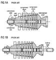
- FIG. 1 is a longitudinal section along an axis of a bladed rotor of a gas turbine, the axis being an axis of rotation. It comprises - left to right looking at the figures -, an axially extending compressor stud, a compressor nut, an inlet shaft, a set of compressor discs, an intermediate shaft, a turbine stud, a set of turbine discs and a turbine nut.
- figure 1 shows different stages of assembly of the gas turbine arrangement. Please note that the order of assembly may be different to the sequence as explained in the following.
- a threaded compressor stud is rotated into threaded engagement into a threaded bore in an intermediate shaft and compressor discs are slid over the compressor stud from left to right during assembly.
- An inlet shaft is then mounted onto the compressor stud and a compressor pre-load nut threaded onto the compressor stud end.
- a hydraulic tool is applied to stretch the stud and the compressor nut is tightened to engage the inlet shaft before the tool is removed. This retains the pre-load applied to the compressor stud.
- the stretch required may be affected by relative thermal and mechanical expansion and contraction at different operating conditions of the stud and the clamped components.
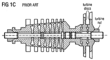
- Figure 1B shows a turbine stud threaded into another axial end of the intermediate shaft. Then - not yet shown in figure 1B - the next stage is to assemble the turbine discs onto the turbine stud from right to left with a turbine nut being threaded onto the other end of the turbine stud, as shown in figure 1C .
- the hydraulic tool is applied to stretch the turbine stud and the nut is tightened to retain the pre-load when the tool is removed.
- EP 0742634 A2 a compound shaft is disclosed.
- a first stiff shaft is connected to a second stiff shaft via a flexible disk shaft.
- the present invention seeks to mitigate these drawbacks.
- a gas turbine engine comprising a rotor rotatably mounted in a body about an axis, an axial direction being defined along the axis in downstream direction of a main fluid path of the gas turbine engine i.e.
- the rotor comprising a stud - a tension stud -, a first set of rotating elements of a first section of the gas turbine engine, the first section being a compressor section or at least an upstream section of a compressor section of the gas turbine engine, and a second set of rotating elements of a second section, particularly a turbine section or a further compressor section, of the gas turbine engine, the first and second set of rotating elements particularly being discs - particularly compressor discs to hold compressor blades and/or turbine discs to hold turbine blades - and/or shafts.
- the stud extends along the axis and comprises a first external end and a second external end, the first external end being adapted to engage a first pre-load nut or one of the shafts and the second external end being adapted to engage a second pre-load nut or one of the shafts such that the set of rotating elements are secured - e.g. clamped -, the stud further comprises, a first shank connected to the first external end and a second shank connected to the second external end.
- the first shank is located in the first section and has a first diameter.
- the second shank is located in the second section and has a second diameter greater than the first diameter.
- first shank is tapered such that the first diameter increases in an axial direction and/or the second shank (16B) is tapered such that the second diameter increases in an axial direction if the second section is a compressor section or decreases in an axial direction if the second section is a turbine section.
- the first diameter is adapted for temperatures occurring in the first section during operation of the gas turbine engine
- the second diameter is adapted for temperatures occurring in the second section during operation of the gas turbine engine.
- the axis is particularly an axis of rotation of the gas turbine engine and is directed in downstream direction of a main fluid path from an inlet of the gas turbine engine in direction of an outlet.
- the axial direction may be defined as corresponding to a downstream fluid flow of a working fluid through the first section and/or the second section during operation of the gas turbine engine.
- a radial direction may be defined a direction starting from the axis and being located in a plane perpendicular to the axis.
- the stud may particularly be a single or monolithic stud. It may be build from one piece. It may be a unitary constructed stud.
- the first shank may be connected via an intermediate part to the second shank.
- this intermediate part may be implemented as a shoulder that may be present between the first shank and the second shank such that the first shank may be located between the first external end and the shoulder and the second shank may be located between the shoulder and the second external end.
- the shoulder may provide for example a surface - particularly cylindrical - to which a shaft or a disc can be connected which may restrict vibration of the stud by contacting the inner surface of a disc opposing the shoulder if the stud vibrates.
- a vibration damper may be located between an outer shoulder surface and an opposing disc.
- a shaft or shaft element a part of the rotor is meant that rotates around the axis and may be connected to the discs. Possibly a shaft may be connected or at least in contact with the shoulder and/or the first external end and/or the second external end. A shaft may also hold blades but may have a larger axial length than a disc.
- the diameters may be diameters of the shanks at a specific axial position - e.g. in the middle of the specific shank - or may be an average value for diameters of the specific shank.
- the diameters will be determined in a plane perpendicular to the axis.
- Adapted for temperatures means that specifics of a material of the shanks and of the temperature gradient at axial positions on the stud are observed.
- a gas turbine engine according to the invention will operate with a temperature gradient in the stud, in which the temperatures in the first region will be less than the temperatures in the second region.
- first shank and the shape of the second shank are adapted for temperatures occurring in the area of the first shank and the second shank respectively during operation.
- the invention is particularly advantageous that a required amount of stretch can be achieved on the stud with a reduced pre-load. This is because the thinner section of the shank allows to have a smaller load to achieve the same amount of stretch i.e. a 10% reduction in cross sectional area will give the same stretch with a 10% lower load. This means that the maximum load transmitted through stud threads for connection to the shafts or discs is reduced, and the fatigue life of the threads is increased.
- load a clamping force is meant applied by the stud or the pre-load nuts to the discs.
- this force may be experienced at the first pre-load nut in axial downstream direction and furthermore may be experienced at the second pre-load nut in axial upstream direction.
- the stud has several different diameters, and at least a tapered cross section.
- first shank may have a cylindrical surface or the second shank may have a cylindrical surface.
- the first diameter increases corresponding to a temperature gradient in the first section.
- the second section may be being a compressor section and the second shank may be tapered such that the second diameter increases in axial direction.
- the tapering may correspond to a temperature gradient in the second section.
- the axial direction may also be defined as corresponding to a downstream fluid flow of a working fluid through the second section during operation of the gas turbine engine.
- the second section may be a turbine section and the second shank may be tapered such that the second diameter decreases in axial direction.
- the tapering may correspond to a temperature gradient in the second section.
- the axial direction may also be defined as corresponding to a downstream fluid flow of a working fluid through the second section during operation of the gas turbine engine.
- the first shank may have a conical surface and/or the second shank may have a conical surface.
- the first shank may have a funnel shaped surface and/or the second shank may have a funnel shaped surface.
- funnel shaped a form is meant for which the surfaces do not form a straight line in a cross section through the axis but showing section of a substantially concave curve.
- an example of a funnel shaped body can be seen under http://mathworld.wolfram.com/Funnel.html. Ignoring the possibly present shoulder between the shanks, a further embodiment may look like a pseudosphere as visualised under http://mathworld.wolfram.com/Pseudosphere.html. This can be compared to two funnel shaped surfaces arranged opposite to each other.
- the value of the second diameter may be substantially X times of the value of the first diameter, wherein X may be substantially 1.05 or 1.1 or 1.2 or 1.3 or 1.4, or 1.5.
- average values for each shank may be compared. Also values at an axially middle position of the respective shank may be taken.
- both shanks will be having increasing diameters in downstream direction, than corresponding positions may be compared, like a diameter value after e.g. 20% of the length of the first shank taken from an upstream end of the first shank will be compared to a value a diameter value after 20% - identical to the measuring position of the first shank - of the length of the second shank taken from an upstream end of the second shank.
- first shank will be having increasing diameter in downstream direction and the second shank decreasing diameter in downstream direction
- corresponding positions may be compared, like a diameter value after e.g. 20% of the length of the first shank taken from an upstream end of the first shank will be compared to a value a diameter value after 20% - identical to the measuring position of the first shank - of the length of the second shank taken from a downstream end of the second shank.
- FIG. 1 was already discussed in the introductory section and show a prior art configuration of a gas turbine engine and how the rotor will be assembled.
- FIG. 2 a part of a gas turbine engine 1 is schematically shown in a cross sectional view with a cross section through an axis A, particularly rotating elements within a compressor section as a first section 2 and within a turbine section as a second section 3, and an intermediate shaft element 21 to interconnect a first set of rotating elements of the compressor section - compressor discs 20 - and the turbine section - turbine discs 30.
- No stator parts are shown, like a casing, guide vanes, mounting brackets, bearings, etc. Also a fluid inlet, combustion chambers, an exhaust and all kind of transitional pieces for the main fluid path are not shown.
- the main fluid may be compressed along the fluid path in the compressor, which also has an effect on the temperature of the fluid. Fluid near the inlet of the compressor will have a lesser temperature than near the outlet of the compressor. This temperature gradient in the main fluid path may have an effect on the temperatures of the compressor discs and the tension stud present in that region.
- the tension stud may also have a temperature gradient along axial direction.
- the hot fluid will cool along the flow direction. Therefore again a temperature gradient will occur that also has an effect on the turbine discs and the tension stud. In this case higher temperatures will be present near the inlet of the turbine and lower temperatures will be present near the outlet of the turbine section.
- FIG. 2 a fully assembled rotor of a gas turbine engine 1 is shown.
- a tension stud is present, around which revolvable shaft elements 21, revolvable compressor discs 20 and revolvable turbine discs 30 are positioned. All of the shaft elements 21 and discs 20, 30 may be interlocked axially between axially adjacent rotating parts - e.g. via set of corresponding teeth in the shaft elements 21 and the discs 20 - and tension is applied to clamp together all these rotating parts via a first pre-load nut 40 applied to a first external end 12 of the tension stud 10 and via a second pre-load nut 41 applied to a second external end 13 of the tension stud 10.
- the first external end 12 and the second external end 13 of the tension stud 10 may be arranged with an outside or male thread and the pre-load nuts 40, 41 with an internal or female thread, each matching the thread of the respective first and second external ends 12, 13.
- the revolvable compressor discs 20 are shown with radially extending compressor blades 104 and the revolvable turbine discs 30 are shown with radially extending compressor blades 103.
- the tension stud 10 comprises starting from the first external end 12 and proceeding in axial direction the first external end 12, a first shank 15, a shoulder 14 that provides support to a shaft 21, a second shank 16 and the second external end 13.
- the shanks 15, 16 may be rotational symmetric parts that have a lesser radial extension than the external ends 12, 13 and the shoulder 14. According to figure 2 , the shanks 15, 16 may be of cylindrical form, the first shank 15 having a first diameter D1 in radial direction which is substantially identical over the axial length of the first shank 15. The second shank 16 having a second diameter D2 in radial direction which is substantially identical over the axial length of the second shank 16.
- first shank 15 has a cylindrical surface. Furthermore also the second shank 16 has a cylindrical surface.
- both shanks have to be cylindrical or both shanks have to be tapered. This freely can be combined so that features from the different embodiments can also be combined.
- the first diameter D1 is less than the second diameter D2. Therefore less material may be used in a first axial section of the first shank 15 than in a second axial section of the same length as the first axial section of the second shank 16.
- the shoulder 14 may be threadless to simply provide an opposing surface to the shaft 21.
- the shoulder 14 may comprise an outside thread and the shaft 21 an inside thread such that the shoulder 14 may be screwed in the shaft 21.
- the first and or the second pre-load nuts 40, 41 are used to apply tension on these parts in axial direction such that these parts get clamped together.
- the first and/or the second pre-load nuts 40, 41 may have an outer conical surface as shown in the figure which matches a surface of an opposing shaft - the shaft 21 in figure 2 on the left - or an opposing disc - the disc 30 in figure 2 on the right - such that the respective pre-load nut 40, 41 can generate, when tightened, an axial force such that all rotating parts are clamped together.
- the tension stud 10 may only be in physical contact with the upstream shaft element 21, the other shaft element 21 and the most downstream turbine disc 30 and the pre-load nuts 40, 41.
- the inner diameter of the discs 20, 30 may be larger than the corresponding outer diameter of the shanks 15, 16 so that the discs will only be held in place by the interlocking means between the discs 20, 30 and shaft elements 21.
- the discs may have a central hole, big enough for the tension stud 10 to fit through for assembly.
- pre-load nuts may be present.
- pre-load nuts may be of a different form.
- shaft 21 and discs 20, 30 may not be always clear, as for example the shaft 21 in the centre in the figure also is equipped with compressor blades 104 and therefore could also be considered to be a compressor disc.
- a main point of the inventive idea is directed to the form of the tension stud 10.
- a first section 2 - in figure 2 corresponding to a compressor section of the gas turbine engine 1 - the first diameter D1 of the first shank 15 may be less than the second diameter D2 of the second shank 16 in a second section 3 which corresponds in figure 2 a turbine section of the gas turbine engine 1.
- a fluid - for example air - will be compressed in the compressor section resulting in a temperature gradient with increasing temperatures from left to right, such that the temperature of the fluid increases.
- the fluid is guided to a combustor - not shown -, mixed with a fuel and ignited.
- the fuel and fluid mixture Due to the ignition, the fuel and fluid mixture is heated and accelerated and guided to the turbine section of the gas turbine engine 1. Within the turbine section the hot fuel and fluid mixture is directed to the turbine blades 103 such that heat is transferred to the turbine blades 103 and to the turbine discs 30. This heat transfer may be supported by cooling means to cool hot surfaces and to guide away heat to a different area and to different parts. Consequently there will be a temperature gradient with decreasing temperatures from left to right within the turbine section.
- the temperature of the tension stud 10 in the region of the compressor section, thus in the region of the first shank 15, may be substantially less than the temperature of the tension stud 10 in the region of the turbine section, thus in the region of the second shank 16.
- the first diameter D1 of the first shank 15 is less than the second diameter D2 of the second shank 16 in a second section 3. This accommodates to physical effects as explained in the following.
- a tension stud or bolt is used in compressor and turbine sections of a gas turbine to clamp together a number of discs and shafts.
- the stud is stretched during assembly, and the amount of stretch must be sufficient to ensure adequate clamping load on the components at all operating conditions.
- the stretch required is affected by relative thermal and mechanical expansion and contraction of the stud and the clamped components.
- a large axial load is applied to the stud during assembly. This load varies through the operating cycle, and is reduced to zero when the compressor or turbine is disassembled.
- the stud is typically attached to a shaft or nut with a threaded connection.
- the axial load applied to the stud is transmitted through the threads, which have a significant stress concentration factor.
- the fatigue life of the stud may often limited by the threads.
- the inventive idea provides a means to achieve the required stretch with a reduced axial load, and an increased thread fatigue life.
- the invention takes advantage of the temperature gradient that exists down the length of the stud in axial direction.
- the stud material will typically have higher strength at lower temperatures.
- the first diameter D1 of the first shank 15 or bolt is reduced. Nevertheless the stud 10 and particularly the first shank 15 still have sufficient strength for fault conditions.
- the bolt diameter in hotter sections - the second diameter D2 of second shank 16 - is larger because the strength of the material is reduced at high temperatures.
- An advantage of the invention is that the required amount of stretch can be achieved on the tension stud or bolt with a reduced load. This is because the thinner section of the stud requires a smaller load to achieve the same amount of stretch i.e. a 10% reduction in cross sectional area will give the same stretch with a 10% lower load. This means that the maximum load transmitted through the stud threads is reduced, and the fatigue life of the threads is increased.
- the stud 10 according to FIG. 2 allows to use less material in the first shank 15 than in a prior art stud.
- two studs 10 and 11 are used with a gas turbine engine 1. This is similar to the example of Figure 1 .
- the to be discussed stud 10 with the two sections 2 and 3 is completely located within a compressor section of the gas turbine engine 1.
- the stud 10 may be inserted into a threaded shaft 31 which is in the region of the combustion chambers and provides a transition between the discs of the compressor and the discs of the turbine.
- a shaft 21 at an upstream end of the compressor the shaft 21 also acting as a disc for supporting compressor blades 104, and a further downstream disc 20 - also supporting further compressor blades 104 - are located in a first region 2 of a first shank 15.
- the first shank 15 is followed in axial direction by a shoulder 14, a second shank 16, and finally a second external end 13, similar to FIG. 2 .
- the axial expansion of the second shaft 16 is again identified as the second region 3.
- the stud 10 Upstream of the first region 2 the stud 10 comprises a first external end 12 with an external thread, which allows to screw a threaded first pre-load nut 40 on the first external end 12 in downstream direction. In contrast to FIG. 2 no pre-load nut will be applied to the second external end 13, as the second external end 13 is connected via threads to the shaft 31.
- a further stud 11 is provided for a turbine section.
- the further stud 11 will only have one turbine shank 102, similar to FIG. 1C , but possibly the further stud 11 may also be arranged as the stud 10 in the compressor section with two shanks and an intermediate shoulder.
- a first diameter D1 of the first shank 15 is less than a second diameter D2 of the second shank 16.
- the difference in diameters may be less than in the previous embodiment according to FIG.2 because the temperature difference between the two regions 2, 3 - both within the compressor section - is clearly less than the temperature difference between the compressor section and the turbine section, as in FIG. 2 .
- the first diameter D1 of the first shank 15 can be less than the second diameter D2. Still the same benefits can be gained, i.e. less material is used for the first shank 15. Therefore a required stretch can be achieved on the stud with a reduced load.
- the shanks 15, 16 are in form of a cylinder.
- the stud could have several different diameters, or even a tapered cross section.
- FIG. 4 only the studs are shown from a radial side view without the to be rotated parts surrounding the stud.
- FIG. 4 is directed to shanks having a tapered form.
- a stud 10 according to FIG. 4A can be used for a gas turbine as shown in FIG. 2 , such that a first shank 15A is located in a compressor section - first section 2 - and a second shank 16A is located in a turbine section - second section 3.
- the shanks 15A, 15B are tapered, e.g. in a conical shape, such that the first diameter D1 increases in downstream direction and the second diameter D2 increases in downstream direction.
- the diameter of D1 may be less than the diameter D2, if measured at a corresponding position, e.g. both taken in the middle of each shank 15A, 16A or both taken at a position near the first external end 12 or the second external end 13. Also average values can be calculated for the diameters. In this case an average first diameter D1 may be less than an average second diameter D2.
- the form of the stud 10 can be adapted to the temperature gradient within the operating gas turbine.
- FIG. 4B shows a configuration that could be applied to a gas turbine according to FIG. 3 , in which both sections 2 and 3 are located in a compressor section. Therefore a first shank 15A will have an increasing diameter in downstream direction and also a second shank 16B will have an increasing diameter, both following the temperature gradient in the compressor section.
- the diameter of D1 may be less than the diameter D2, if measured at a corresponding position, e.g. both taken in the middle of each shank 15A, 16B or both taken at a most upstream position or both taken at a most downstream position.
- average values can be calculated for the diameters. In this case an average first diameter D1 may be less than an average second diameter D2.
- FIG. 4 a further detail is shown, that could also be implemented in the studs according to FIG. 2 and 3 .
- the stud 10 according to FIG. 4 has no abrupt ledges between the external end 12 (or 13) and the shank 15A (or 16A/16B) or between the shoulder 14 and the shanks 15A or 16A/16B.
- a transition piece is shown as a tapered section so that no points of stress are created.
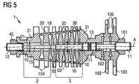
- Fig. 5 shows a similar gas turbine engine as FIG. 3 , with the difference that the shoulder 14 is replaced by an intermediate section 18.
- the intermediate section 18 does not touch the discs 20, 30 or the shafts 21, 31. It merely provides a transition from the first shank 15 to the second shank 16.
- the intermediate section 18 is of conical shape such that it adapts to the difference in diameter between the first diameter D1 and the second diameter D2.
- the intermediate section 18 can have a variety of forms. It can be conical, it can be funnel shaped. Besides, there may be a smooth transition between the two diameters.
- the invention takes advantage of the temperature gradient on the surface of the stud down the length of the stud during operation of the gas turbine engine.
- the stud diameter in hotter sections will be larger than in cooler section. This allows to gain a strength to withstand the loads that may occur during a fault condition, such as loss of one or more aerofoils or blades, even though the diameter of the stud may be less than in a prior art stud.
- Such a prior art tension stud may have a constant shank diameter except for local thickened areas to locate on the disc bores and larger diameter threads at the ends.
- the invention may be applied to different kind of axial turbomachines or other kind of rotating machines that experience a temperature gradient along its axis of rotation.
Landscapes
- Engineering & Computer Science (AREA)
- Mechanical Engineering (AREA)
- General Engineering & Computer Science (AREA)
- Structures Of Non-Positive Displacement Pumps (AREA)
- Chemical & Material Sciences (AREA)
- Combustion & Propulsion (AREA)
Claims (14)
- Gasturbine (1) mit einem Rotor (10, 20, 21, 30, 31, 40, 41), der um eine Achse (A) drehbar in einem Körper angebracht ist, wobei in Strömungsrichtung eines Hauptfluidwegs eine axiale Richtung entlang der Achse (A) definiert ist, wobei der Rotor Folgendes umfasst:- einen Bolzen (10),- einen ersten Satz rotierende Elemente (20, 21) eines ersten Abschnitts (2) der Gasturbine (1), wobei es sich bei dem ersten Abschnitt (2) um einen Kompressorabschnitt der Gasturbine (1) handelt,- einen zweiten Satz rotierende Elemente (30, 31) eines zweiten Abschnitts (3) der Gasturbine (1),wobei der Bolzen (10, 11) an der Achse (A) entlang verläuft und Folgendes umfasst:- ein erstes äußeres Ende (12) und ein zweites äußeres Ende (13), wobei das erste äußere Ende (12) zum Ineingriffnehmen einer ersten Vorspannmutter (40) oder einer von mehreren Wellen (21) und das zweite äußere Ende (13) zum Ineingriffnehmen einer zweiten Vorspannmutter (41) oder einer der Wellen (31) ausgelegt ist, so dass der Satz rotierende Elemente (20, 21, 30, 31) gesichert ist,- einen ersten Schaft (15), der mit dem ersten äußeren Ende (12) verbunden ist, und- einen zweiten Schaft (16), der mit dem zweiten äußeren Ende (13) verbunden ist,wobei sich der erste Schaft (15) in dem ersten Abschnitt (2) befindet und einen ersten Durchmesser (D1) aufweist,
wobei sich der zweite Schaft (16) in dem zweiten Abschnitt (3) befindet,
dadurch gekennzeichnet, dass
der zweite Schaft (16) einen zweiten Durchmesser (D2) aufweist, der größer ist als der erste Durchmesser (D1), und- sich der erste Schaft (15A) so verjüngt, dass der erste Durchmesser (D1) in einer axialen Richtung zunimmt, und/ oder- sich der zweite Schaft (16B) so verjüngt, dass der zweite Durchmesser (D2) in axialer Richtung zunimmt, wenn es sich bei dem zweiten Abschnitt (3) um einen Kompressorabschnitt handelt, oder in axialer Richtung abnimmt, wenn es sich bei dem zweiten Abschnitt (3) um einen Turbinenabschnitt handelt. - Gasturbine (1) nach Anspruch 1,
dadurch gekennzeichnet, dass
der erste Schaft (15) oder der zweite Schaft (16) eine zylinderförmige Oberfläche aufweist. - Gasturbine (1) nach Anspruch 1 oder 2,
dadurch gekennzeichnet, dass
sich der erste Schaft (15A) so verjüngt, dass der erste Durchmesser (D1) einem Temperaturgradienten in dem ersten Abschnitt (2) entsprechend in axialer Richtung zunimmt. - Gasturbine (1) nach Anspruch 1 oder 2 oder 3,
dadurch gekennzeichnet, dass
es sich bei dem zweiten Abschnitt (3) um einen Kompressorabschnitt handelt und sich der zweite Schaft (16B) so verjüngt, dass der zweite Durchmesser (D2) in axialer Richtung zunimmt. - Gasturbine (1) nach Anspruch 1 oder 2 oder 3 oder 4,
dadurch gekennzeichnet, dass
sich der zweite Schaft (16B) so verjüngt, dass der zweite Durchmesser (D2) einem Temperaturgradienten im zweiten Abschnitt (3) entspricht. - Gasturbine (1) nach Anspruch 1 oder 2 oder 3,
dadurch gekennzeichnet, dass
es sich bei dem zweiten Abschnitt (3) um einen Turbinenabschnitt handelt und
sich der zweite Schaft (16A) so verjüngt, dass der zweite Durchmesser (D2) in axialer Richtung abnimmt. - Gasturbine (1) nach Anspruch 1 oder 2 oder 3 oder 6,
dadurch gekennzeichnet, dass
sich der zweite Schaft (16B) so verjüngt, dass der zweite Durchmesser (D2) einem Temperaturgradienten im zweiten Abschnitt (3) entspricht. - Gasturbine (1) nach einem der Ansprüche 3 bis 7,
dadurch gekennzeichnet, dass
der erste Schaft (15A) und/ oder der zweite Schaft (16A, 16B) eine konische Oberfläche hat. - Gasturbine (1) nach einem der Ansprüche 3 bis 7,
dadurch gekennzeichnet, dass
der erste Schaft (15A) und/ oder der zweite Schaft (16A, 16B) eine trichterförmige Oberfläche hat. - Gasturbine (1) nach einem der vorhergehenden Ansprüche,
dadurch gekennzeichnet, dass
der Bolzen (10, 11) ferner einen Absatz (14) umfasst, so dass der erste Schaft (15) zwischen dem ersten äußeren Ende (12) und dem Absatz (14) und der zweite Schaft (16) zwischen dem Absatz (14) und dem zweiten äußeren Ende (13) liegt. - Gasturbine (1) nach einem der vorhergehenden Ansprüche,
dadurch gekennzeichnet, dass
der Wert des zweiten Durchmessers (D2) im Wesentlichen das X-fache des Werts des ersten Durchmessers (D1) beträgt, wobei X 1,1 oder 1,2 oder 1,3 oder 1,4 ist. - Gasturbine (1) nach einem der vorhergehenden Ansprüche,
dadurch gekennzeichnet, dass
der zweite Abschnitt (3) ein Turbinenabschnitt der Gasturbine (1) ist. - Gasturbine (1) nach einem der vorhergehenden Ansprüche,
dadurch gekennzeichnet, dass
der zweite Abschnitt (3) ein weiterer Kompressorabschnitt der Gasturbine (1) ist. - Gasturbine (1) nach einem der vorhergehenden Ansprüche,
dadurch gekennzeichnet, dass
es sich bei dem ersten und dem zweiten Satz rotierende Elemente (20, 21, 30, 31) um Scheiben (20, 30) und/ oder Wellen (21, 31) handelt.
Priority Applications (1)
| Application Number | Priority Date | Filing Date | Title |
|---|---|---|---|
| EP11740642.1A EP2601384B1 (de) | 2010-08-03 | 2011-08-02 | Gasturbinenmotor mit einem spannungsbolzen |
Applications Claiming Priority (3)
| Application Number | Priority Date | Filing Date | Title |
|---|---|---|---|
| EP10171715A EP2415967A1 (de) | 2010-08-03 | 2010-08-03 | Gasturbinenmotor mit Spannungsbolzen |
| PCT/EP2011/063288 WO2012016981A1 (en) | 2010-08-03 | 2011-08-02 | Gas turbine engine comprising a tension stud |
| EP11740642.1A EP2601384B1 (de) | 2010-08-03 | 2011-08-02 | Gasturbinenmotor mit einem spannungsbolzen |
Publications (2)
| Publication Number | Publication Date |
|---|---|
| EP2601384A1 EP2601384A1 (de) | 2013-06-12 |
| EP2601384B1 true EP2601384B1 (de) | 2016-03-23 |
Family
ID=43244807
Family Applications (2)
| Application Number | Title | Priority Date | Filing Date |
|---|---|---|---|
| EP10171715A Withdrawn EP2415967A1 (de) | 2010-08-03 | 2010-08-03 | Gasturbinenmotor mit Spannungsbolzen |
| EP11740642.1A Not-in-force EP2601384B1 (de) | 2010-08-03 | 2011-08-02 | Gasturbinenmotor mit einem spannungsbolzen |
Family Applications Before (1)
| Application Number | Title | Priority Date | Filing Date |
|---|---|---|---|
| EP10171715A Withdrawn EP2415967A1 (de) | 2010-08-03 | 2010-08-03 | Gasturbinenmotor mit Spannungsbolzen |
Country Status (3)
| Country | Link |
|---|---|
| US (1) | US9279327B2 (de) |
| EP (2) | EP2415967A1 (de) |
| WO (1) | WO2012016981A1 (de) |
Families Citing this family (10)
| Publication number | Priority date | Publication date | Assignee | Title |
|---|---|---|---|---|
| EP2672061A1 (de) * | 2012-06-06 | 2013-12-11 | Siemens Aktiengesellschaft | Gewindeschaft, Verbindungsanordnung und Gasturbinenmotor für verlängerte Lebensdauer von Gewinden |
| BR112015004993A2 (pt) * | 2012-09-07 | 2017-07-04 | Siemens Ag | método para montagem de um rotor, método para desmontar parcialmente um rotor e rotor para uma turbomáquina de fluxo axial |
| CA2896870C (en) | 2012-12-31 | 2019-04-16 | Rolls-Royce Corporation | Systems, methods and apparatuses for interconnection of rotating components |
| FR3039857B1 (fr) * | 2015-08-04 | 2019-09-13 | Safran Aircraft Engines | Procede et dispositif de serrage d'une ligne rotor de turbomachine |
| CN107023321A (zh) * | 2017-05-31 | 2017-08-08 | 深圳智慧能源技术有限公司 | 多级高速汽轮机的定心传扭锁紧组合机构 |
| EP3647536A1 (de) * | 2018-10-30 | 2020-05-06 | Siemens Aktiengesellschaft | Sicherheitsvorrichtung |
| EP3647539A1 (de) * | 2018-10-30 | 2020-05-06 | Siemens Aktiengesellschaft | Sicherheitsvorrichtung |
| EP3647537A1 (de) * | 2018-10-30 | 2020-05-06 | Siemens Aktiengesellschaft | Sicherheitsvorrichtung zum eindämmen einer energiefreisetzung in einem zuganker einer rotoren-anordnung und zugehöriges verfahren |
| US11519271B2 (en) * | 2020-06-05 | 2022-12-06 | Rolls-Royce North American Technologies Inc. | Turbine engine rotor with flexibly coupled tie bolt |
| CN117027957A (zh) * | 2023-08-29 | 2023-11-10 | 中国航发贵阳发动机设计研究所 | 一种用于涡轮转子连接的螺栓连接结构及方法 |
Family Cites Families (8)
| Publication number | Priority date | Publication date | Assignee | Title |
|---|---|---|---|---|
| GB898163A (en) * | 1960-01-21 | 1962-06-06 | Austin Motor Co Ltd | Improvements relating to gas turbines |
| GB898153A (en) | 1960-03-03 | 1962-06-06 | Weiss Maschf Johann | An improved process and apparatus for labelling upright-standing articles, more particularly bottles |
| GB1249863A (en) * | 1968-01-22 | 1971-10-13 | Lucas Industries Ltd | Gas bearings |
| US4060337A (en) * | 1976-10-01 | 1977-11-29 | General Motors Corporation | Centrifugal compressor with a splitter shroud in flow path |
| US5697848A (en) * | 1995-05-12 | 1997-12-16 | Capstone Turbine Corporation | Compound shaft with flexible disk coupling |
| US6499969B1 (en) * | 2000-05-10 | 2002-12-31 | General Motors Corporation | Conically jointed turbocharger rotor |
| GB0304320D0 (en) * | 2003-02-26 | 2003-04-02 | Bladon Jets Ltd | Gas turbine engines |
| GB2452932B8 (en) * | 2007-09-19 | 2011-08-10 | Siemens Ag | A turbine and a method of manufacture |
-
2010
- 2010-08-03 EP EP10171715A patent/EP2415967A1/de not_active Withdrawn
-
2011
- 2011-08-02 WO PCT/EP2011/063288 patent/WO2012016981A1/en not_active Ceased
- 2011-08-02 US US13/813,272 patent/US9279327B2/en not_active Expired - Fee Related
- 2011-08-02 EP EP11740642.1A patent/EP2601384B1/de not_active Not-in-force
Also Published As
| Publication number | Publication date |
|---|---|
| WO2012016981A1 (en) | 2012-02-09 |
| EP2415967A1 (de) | 2012-02-08 |
| US20130125559A1 (en) | 2013-05-23 |
| US9279327B2 (en) | 2016-03-08 |
| EP2601384A1 (de) | 2013-06-12 |
Similar Documents
| Publication | Publication Date | Title |
|---|---|---|
| US9279327B2 (en) | Gas turbine engine comprising a tension stud | |
| US7942635B1 (en) | Twin spool rotor assembly for a small gas turbine engine | |
| KR100204743B1 (ko) | 압축기 케이스의 구조체 및 외부케이스 조립방법 | |
| US9695692B2 (en) | Threaded shank, connection assembly and gas turbine engine for improved fatigue life of threads | |
| CN105308265B (zh) | 包括设置在系轴和转子之间的壳的燃气涡轮机系轴装置 | |
| US8047781B2 (en) | Bolt assembly for steam turbine engines and method of assembling the same | |
| US8267649B2 (en) | Coupling for rotary components | |
| US20160097283A1 (en) | Compressor impeller assembly for a turbocharger | |
| US8668463B2 (en) | Rotatable component mount for a gas turbine engine | |
| US9885386B2 (en) | Bearing assembly | |
| KR102261350B1 (ko) | 터빈 노즐 고정 방법 및 시스템 | |
| US20170284411A1 (en) | Shaft and a turbomachine | |
| US11028709B2 (en) | Airfoil shroud assembly using tenon with externally threaded stud and nut | |
| US20110239661A1 (en) | Rotor for a gas turbine engine comprising a rotor spool and a rotor ring | |
| CN105392966A (zh) | 用于涡轮机的定子的密封环段 | |
| KR20080018821A (ko) | 증기 터빈용 로터의 제조 방법 및 장치 | |
| EP3647540B1 (de) | Turbinenrotorverriegelungsanordnung und -verfahren | |
| KR101783906B1 (ko) | 가스 터빈 엔진의 로터 조립체 | |
| US12460582B2 (en) | Assembly for a turbine engine | |
| WO2014143319A2 (en) | Turbomachine with clamp coupling shaft and rotor hub together | |
| CN113677871B (zh) | 用于在反向旋转涡轮中连接叶片的改进装置 | |
| JP2009216094A (ja) | 蒸気タービンロータ及びその組立方法 | |
| CN118407808A (zh) | 具有拉杆的燃气涡轮发动机 |
Legal Events
| Date | Code | Title | Description |
|---|---|---|---|
| PUAI | Public reference made under article 153(3) epc to a published international application that has entered the european phase |
Free format text: ORIGINAL CODE: 0009012 |
|
| 17P | Request for examination filed |
Effective date: 20121122 |
|
| AK | Designated contracting states |
Kind code of ref document: A1 Designated state(s): AL AT BE BG CH CY CZ DE DK EE ES FI FR GB GR HR HU IE IS IT LI LT LU LV MC MK MT NL NO PL PT RO RS SE SI SK SM TR |
|
| DAX | Request for extension of the european patent (deleted) | ||
| 17Q | First examination report despatched |
Effective date: 20140612 |
|
| REG | Reference to a national code |
Ref country code: DE Ref legal event code: R079 Ref document number: 602011024329 Country of ref document: DE Free format text: PREVIOUS MAIN CLASS: F01D0005060000 Ipc: F02C0007200000 |
|
| RIC1 | Information provided on ipc code assigned before grant |
Ipc: F02C 7/20 20060101AFI20150126BHEP Ipc: F01D 5/06 20060101ALI20150126BHEP |
|
| GRAP | Despatch of communication of intention to grant a patent |
Free format text: ORIGINAL CODE: EPIDOSNIGR1 |
|
| INTG | Intention to grant announced |
Effective date: 20150324 |
|
| GRAP | Despatch of communication of intention to grant a patent |
Free format text: ORIGINAL CODE: EPIDOSNIGR1 |
|
| GRAJ | Information related to disapproval of communication of intention to grant by the applicant or resumption of examination proceedings by the epo deleted |
Free format text: ORIGINAL CODE: EPIDOSDIGR1 |
|
| GRAP | Despatch of communication of intention to grant a patent |
Free format text: ORIGINAL CODE: EPIDOSNIGR1 |
|
| INTG | Intention to grant announced |
Effective date: 20150922 |
|
| INTG | Intention to grant announced |
Effective date: 20151002 |
|
| GRAS | Grant fee paid |
Free format text: ORIGINAL CODE: EPIDOSNIGR3 |
|
| GRAA | (expected) grant |
Free format text: ORIGINAL CODE: 0009210 |
|
| AK | Designated contracting states |
Kind code of ref document: B1 Designated state(s): AL AT BE BG CH CY CZ DE DK EE ES FI FR GB GR HR HU IE IS IT LI LT LU LV MC MK MT NL NO PL PT RO RS SE SI SK SM TR |
|
| REG | Reference to a national code |
Ref country code: GB Ref legal event code: FG4D |
|
| REG | Reference to a national code |
Ref country code: CH Ref legal event code: EP |
|
| REG | Reference to a national code |
Ref country code: AT Ref legal event code: REF Ref document number: 783404 Country of ref document: AT Kind code of ref document: T Effective date: 20160415 |
|
| REG | Reference to a national code |
Ref country code: IE Ref legal event code: FG4D |
|
| REG | Reference to a national code |
Ref country code: DE Ref legal event code: R096 Ref document number: 602011024329 Country of ref document: DE |
|
| REG | Reference to a national code |
Ref country code: LT Ref legal event code: MG4D |
|
| REG | Reference to a national code |
Ref country code: NL Ref legal event code: MP Effective date: 20160323 |
|
| PG25 | Lapsed in a contracting state [announced via postgrant information from national office to epo] |
Ref country code: FI Free format text: LAPSE BECAUSE OF FAILURE TO SUBMIT A TRANSLATION OF THE DESCRIPTION OR TO PAY THE FEE WITHIN THE PRESCRIBED TIME-LIMIT Effective date: 20160323 Ref country code: HR Free format text: LAPSE BECAUSE OF FAILURE TO SUBMIT A TRANSLATION OF THE DESCRIPTION OR TO PAY THE FEE WITHIN THE PRESCRIBED TIME-LIMIT Effective date: 20160323 Ref country code: GR Free format text: LAPSE BECAUSE OF FAILURE TO SUBMIT A TRANSLATION OF THE DESCRIPTION OR TO PAY THE FEE WITHIN THE PRESCRIBED TIME-LIMIT Effective date: 20160624 Ref country code: NO Free format text: LAPSE BECAUSE OF FAILURE TO SUBMIT A TRANSLATION OF THE DESCRIPTION OR TO PAY THE FEE WITHIN THE PRESCRIBED TIME-LIMIT Effective date: 20160623 |
|
| REG | Reference to a national code |
Ref country code: AT Ref legal event code: MK05 Ref document number: 783404 Country of ref document: AT Kind code of ref document: T Effective date: 20160323 |
|
| REG | Reference to a national code |
Ref country code: FR Ref legal event code: PLFP Year of fee payment: 6 |
|
| PG25 | Lapsed in a contracting state [announced via postgrant information from national office to epo] |
Ref country code: LV Free format text: LAPSE BECAUSE OF FAILURE TO SUBMIT A TRANSLATION OF THE DESCRIPTION OR TO PAY THE FEE WITHIN THE PRESCRIBED TIME-LIMIT Effective date: 20160323 Ref country code: LT Free format text: LAPSE BECAUSE OF FAILURE TO SUBMIT A TRANSLATION OF THE DESCRIPTION OR TO PAY THE FEE WITHIN THE PRESCRIBED TIME-LIMIT Effective date: 20160323 Ref country code: RS Free format text: LAPSE BECAUSE OF FAILURE TO SUBMIT A TRANSLATION OF THE DESCRIPTION OR TO PAY THE FEE WITHIN THE PRESCRIBED TIME-LIMIT Effective date: 20160323 Ref country code: SE Free format text: LAPSE BECAUSE OF FAILURE TO SUBMIT A TRANSLATION OF THE DESCRIPTION OR TO PAY THE FEE WITHIN THE PRESCRIBED TIME-LIMIT Effective date: 20160323 Ref country code: NL Free format text: LAPSE BECAUSE OF FAILURE TO SUBMIT A TRANSLATION OF THE DESCRIPTION OR TO PAY THE FEE WITHIN THE PRESCRIBED TIME-LIMIT Effective date: 20160323 |
|
| PG25 | Lapsed in a contracting state [announced via postgrant information from national office to epo] |
Ref country code: PL Free format text: LAPSE BECAUSE OF FAILURE TO SUBMIT A TRANSLATION OF THE DESCRIPTION OR TO PAY THE FEE WITHIN THE PRESCRIBED TIME-LIMIT Effective date: 20160323 Ref country code: IS Free format text: LAPSE BECAUSE OF FAILURE TO SUBMIT A TRANSLATION OF THE DESCRIPTION OR TO PAY THE FEE WITHIN THE PRESCRIBED TIME-LIMIT Effective date: 20160723 Ref country code: EE Free format text: LAPSE BECAUSE OF FAILURE TO SUBMIT A TRANSLATION OF THE DESCRIPTION OR TO PAY THE FEE WITHIN THE PRESCRIBED TIME-LIMIT Effective date: 20160323 |
|
| PG25 | Lapsed in a contracting state [announced via postgrant information from national office to epo] |
Ref country code: RO Free format text: LAPSE BECAUSE OF FAILURE TO SUBMIT A TRANSLATION OF THE DESCRIPTION OR TO PAY THE FEE WITHIN THE PRESCRIBED TIME-LIMIT Effective date: 20160323 Ref country code: SK Free format text: LAPSE BECAUSE OF FAILURE TO SUBMIT A TRANSLATION OF THE DESCRIPTION OR TO PAY THE FEE WITHIN THE PRESCRIBED TIME-LIMIT Effective date: 20160323 Ref country code: CZ Free format text: LAPSE BECAUSE OF FAILURE TO SUBMIT A TRANSLATION OF THE DESCRIPTION OR TO PAY THE FEE WITHIN THE PRESCRIBED TIME-LIMIT Effective date: 20160323 Ref country code: SM Free format text: LAPSE BECAUSE OF FAILURE TO SUBMIT A TRANSLATION OF THE DESCRIPTION OR TO PAY THE FEE WITHIN THE PRESCRIBED TIME-LIMIT Effective date: 20160323 Ref country code: AT Free format text: LAPSE BECAUSE OF FAILURE TO SUBMIT A TRANSLATION OF THE DESCRIPTION OR TO PAY THE FEE WITHIN THE PRESCRIBED TIME-LIMIT Effective date: 20160323 Ref country code: ES Free format text: LAPSE BECAUSE OF FAILURE TO SUBMIT A TRANSLATION OF THE DESCRIPTION OR TO PAY THE FEE WITHIN THE PRESCRIBED TIME-LIMIT Effective date: 20160323 Ref country code: PT Free format text: LAPSE BECAUSE OF FAILURE TO SUBMIT A TRANSLATION OF THE DESCRIPTION OR TO PAY THE FEE WITHIN THE PRESCRIBED TIME-LIMIT Effective date: 20160725 |
|
| PG25 | Lapsed in a contracting state [announced via postgrant information from national office to epo] |
Ref country code: IT Free format text: LAPSE BECAUSE OF FAILURE TO SUBMIT A TRANSLATION OF THE DESCRIPTION OR TO PAY THE FEE WITHIN THE PRESCRIBED TIME-LIMIT Effective date: 20160323 Ref country code: BE Free format text: LAPSE BECAUSE OF FAILURE TO SUBMIT A TRANSLATION OF THE DESCRIPTION OR TO PAY THE FEE WITHIN THE PRESCRIBED TIME-LIMIT Effective date: 20160323 |
|
| REG | Reference to a national code |
Ref country code: DE Ref legal event code: R097 Ref document number: 602011024329 Country of ref document: DE |
|
| PLBE | No opposition filed within time limit |
Free format text: ORIGINAL CODE: 0009261 |
|
| STAA | Information on the status of an ep patent application or granted ep patent |
Free format text: STATUS: NO OPPOSITION FILED WITHIN TIME LIMIT |
|
| PG25 | Lapsed in a contracting state [announced via postgrant information from national office to epo] |
Ref country code: DK Free format text: LAPSE BECAUSE OF FAILURE TO SUBMIT A TRANSLATION OF THE DESCRIPTION OR TO PAY THE FEE WITHIN THE PRESCRIBED TIME-LIMIT Effective date: 20160323 |
|
| PG25 | Lapsed in a contracting state [announced via postgrant information from national office to epo] |
Ref country code: BG Free format text: LAPSE BECAUSE OF FAILURE TO SUBMIT A TRANSLATION OF THE DESCRIPTION OR TO PAY THE FEE WITHIN THE PRESCRIBED TIME-LIMIT Effective date: 20160623 |
|
| 26N | No opposition filed |
Effective date: 20170102 |
|
| PG25 | Lapsed in a contracting state [announced via postgrant information from national office to epo] |
Ref country code: MC Free format text: LAPSE BECAUSE OF FAILURE TO SUBMIT A TRANSLATION OF THE DESCRIPTION OR TO PAY THE FEE WITHIN THE PRESCRIBED TIME-LIMIT Effective date: 20160323 |
|
| REG | Reference to a national code |
Ref country code: CH Ref legal event code: PL |
|
| PG25 | Lapsed in a contracting state [announced via postgrant information from national office to epo] |
Ref country code: LI Free format text: LAPSE BECAUSE OF NON-PAYMENT OF DUE FEES Effective date: 20160831 Ref country code: CH Free format text: LAPSE BECAUSE OF NON-PAYMENT OF DUE FEES Effective date: 20160831 |
|
| PG25 | Lapsed in a contracting state [announced via postgrant information from national office to epo] |
Ref country code: SI Free format text: LAPSE BECAUSE OF FAILURE TO SUBMIT A TRANSLATION OF THE DESCRIPTION OR TO PAY THE FEE WITHIN THE PRESCRIBED TIME-LIMIT Effective date: 20160323 |
|
| REG | Reference to a national code |
Ref country code: IE Ref legal event code: MM4A |
|
| PG25 | Lapsed in a contracting state [announced via postgrant information from national office to epo] |
Ref country code: IE Free format text: LAPSE BECAUSE OF NON-PAYMENT OF DUE FEES Effective date: 20160802 |
|
| REG | Reference to a national code |
Ref country code: FR Ref legal event code: PLFP Year of fee payment: 7 |
|
| PG25 | Lapsed in a contracting state [announced via postgrant information from national office to epo] |
Ref country code: LU Free format text: LAPSE BECAUSE OF NON-PAYMENT OF DUE FEES Effective date: 20160802 |
|
| PG25 | Lapsed in a contracting state [announced via postgrant information from national office to epo] |
Ref country code: HU Free format text: LAPSE BECAUSE OF FAILURE TO SUBMIT A TRANSLATION OF THE DESCRIPTION OR TO PAY THE FEE WITHIN THE PRESCRIBED TIME-LIMIT; INVALID AB INITIO Effective date: 20110802 Ref country code: CY Free format text: LAPSE BECAUSE OF FAILURE TO SUBMIT A TRANSLATION OF THE DESCRIPTION OR TO PAY THE FEE WITHIN THE PRESCRIBED TIME-LIMIT Effective date: 20160323 |
|
| PG25 | Lapsed in a contracting state [announced via postgrant information from national office to epo] |
Ref country code: MT Free format text: LAPSE BECAUSE OF NON-PAYMENT OF DUE FEES Effective date: 20160831 Ref country code: MK Free format text: LAPSE BECAUSE OF FAILURE TO SUBMIT A TRANSLATION OF THE DESCRIPTION OR TO PAY THE FEE WITHIN THE PRESCRIBED TIME-LIMIT Effective date: 20160323 Ref country code: TR Free format text: LAPSE BECAUSE OF FAILURE TO SUBMIT A TRANSLATION OF THE DESCRIPTION OR TO PAY THE FEE WITHIN THE PRESCRIBED TIME-LIMIT Effective date: 20160323 |
|
| REG | Reference to a national code |
Ref country code: FR Ref legal event code: PLFP Year of fee payment: 8 |
|
| PG25 | Lapsed in a contracting state [announced via postgrant information from national office to epo] |
Ref country code: AL Free format text: LAPSE BECAUSE OF FAILURE TO SUBMIT A TRANSLATION OF THE DESCRIPTION OR TO PAY THE FEE WITHIN THE PRESCRIBED TIME-LIMIT Effective date: 20160323 |
|
| PGFP | Annual fee paid to national office [announced via postgrant information from national office to epo] |
Ref country code: FR Payment date: 20180822 Year of fee payment: 8 |
|
| PGFP | Annual fee paid to national office [announced via postgrant information from national office to epo] |
Ref country code: GB Payment date: 20180809 Year of fee payment: 8 |
|
| PGFP | Annual fee paid to national office [announced via postgrant information from national office to epo] |
Ref country code: DE Payment date: 20181019 Year of fee payment: 8 |
|
| REG | Reference to a national code |
Ref country code: DE Ref legal event code: R119 Ref document number: 602011024329 Country of ref document: DE |
|
| GBPC | Gb: european patent ceased through non-payment of renewal fee |
Effective date: 20190802 |
|
| PG25 | Lapsed in a contracting state [announced via postgrant information from national office to epo] |
Ref country code: DE Free format text: LAPSE BECAUSE OF NON-PAYMENT OF DUE FEES Effective date: 20200303 Ref country code: FR Free format text: LAPSE BECAUSE OF NON-PAYMENT OF DUE FEES Effective date: 20190831 |
|
| PG25 | Lapsed in a contracting state [announced via postgrant information from national office to epo] |
Ref country code: GB Free format text: LAPSE BECAUSE OF NON-PAYMENT OF DUE FEES Effective date: 20190802 |