EP2601723B1 - Induktive stromempfangsvorrichtung - Google Patents
Induktive stromempfangsvorrichtung Download PDFInfo
- Publication number
- EP2601723B1 EP2601723B1 EP11814854.3A EP11814854A EP2601723B1 EP 2601723 B1 EP2601723 B1 EP 2601723B1 EP 11814854 A EP11814854 A EP 11814854A EP 2601723 B1 EP2601723 B1 EP 2601723B1
- Authority
- EP
- European Patent Office
- Prior art keywords
- coils
- pad
- magnetic flux
- coil
- power
- Prior art date
- Legal status (The legal status is an assumption and is not a legal conclusion. Google has not performed a legal analysis and makes no representation as to the accuracy of the status listed.)
- Active
Links
Images


Classifications
-
- H—ELECTRICITY
- H01—ELECTRIC ELEMENTS
- H01F—MAGNETS; INDUCTANCES; TRANSFORMERS; SELECTION OF MATERIALS FOR THEIR MAGNETIC PROPERTIES
- H01F27/00—Details of transformers or inductances, in general
- H01F27/34—Special means for preventing or reducing unwanted electric or magnetic effects, e.g. no-load losses, reactive currents, harmonics, oscillations, leakage fields
- H01F27/346—Preventing or reducing leakage fields
-
- H—ELECTRICITY
- H01—ELECTRIC ELEMENTS
- H01F—MAGNETS; INDUCTANCES; TRANSFORMERS; SELECTION OF MATERIALS FOR THEIR MAGNETIC PROPERTIES
- H01F27/00—Details of transformers or inductances, in general
- H01F27/28—Coils; Windings; Conductive connections
- H01F27/2823—Wires
-
- H—ELECTRICITY
- H01—ELECTRIC ELEMENTS
- H01F—MAGNETS; INDUCTANCES; TRANSFORMERS; SELECTION OF MATERIALS FOR THEIR MAGNETIC PROPERTIES
- H01F27/00—Details of transformers or inductances, in general
- H01F27/28—Coils; Windings; Conductive connections
- H01F27/288—Shielding
- H01F27/2885—Shielding with shields or electrodes
-
- H—ELECTRICITY
- H01—ELECTRIC ELEMENTS
- H01F—MAGNETS; INDUCTANCES; TRANSFORMERS; SELECTION OF MATERIALS FOR THEIR MAGNETIC PROPERTIES
- H01F38/00—Adaptations of transformers or inductances for specific applications or functions
- H01F38/14—Inductive couplings
-
- H—ELECTRICITY
- H01—ELECTRIC ELEMENTS
- H01F—MAGNETS; INDUCTANCES; TRANSFORMERS; SELECTION OF MATERIALS FOR THEIR MAGNETIC PROPERTIES
- H01F41/00—Apparatus or processes specially adapted for manufacturing or assembling magnets, inductances or transformers; Apparatus or processes specially adapted for manufacturing materials characterised by their magnetic properties
- H01F41/02—Apparatus or processes specially adapted for manufacturing or assembling magnets, inductances or transformers; Apparatus or processes specially adapted for manufacturing materials characterised by their magnetic properties for manufacturing cores, coils, or magnets
- H01F41/04—Apparatus or processes specially adapted for manufacturing or assembling magnets, inductances or transformers; Apparatus or processes specially adapted for manufacturing materials characterised by their magnetic properties for manufacturing cores, coils, or magnets for manufacturing coils
-
- H—ELECTRICITY
- H02—GENERATION; CONVERSION OR DISTRIBUTION OF ELECTRIC POWER
- H02J—ELECTRIC POWER NETWORKS; CIRCUIT ARRANGEMENTS OR SYSTEMS FOR SUPPLYING OR DISTRIBUTING ELECTRIC POWER; SYSTEMS FOR STORING ELECTRIC ENERGY
- H02J50/00—Circuit arrangements or systems for wireless supply or distribution of electric power
- H02J50/005—Mechanical details of housing or structure aiming to accommodate the power transfer means, e.g. mechanical integration of coils, antennas or transducers into emitting or receiving devices
-
- H—ELECTRICITY
- H02—GENERATION; CONVERSION OR DISTRIBUTION OF ELECTRIC POWER
- H02J—ELECTRIC POWER NETWORKS; CIRCUIT ARRANGEMENTS OR SYSTEMS FOR SUPPLYING OR DISTRIBUTING ELECTRIC POWER; SYSTEMS FOR STORING ELECTRIC ENERGY
- H02J50/00—Circuit arrangements or systems for wireless supply or distribution of electric power
- H02J50/10—Circuit arrangements or systems for wireless supply or distribution of electric power using inductive coupling
- H02J50/12—Circuit arrangements or systems for wireless supply or distribution of electric power using inductive coupling of the resonant type
-
- H—ELECTRICITY
- H02—GENERATION; CONVERSION OR DISTRIBUTION OF ELECTRIC POWER
- H02J—ELECTRIC POWER NETWORKS; CIRCUIT ARRANGEMENTS OR SYSTEMS FOR SUPPLYING OR DISTRIBUTING ELECTRIC POWER; SYSTEMS FOR STORING ELECTRIC ENERGY
- H02J50/00—Circuit arrangements or systems for wireless supply or distribution of electric power
- H02J50/70—Circuit arrangements or systems for wireless supply or distribution of electric power involving the reduction of electric, magnetic or electromagnetic leakage fields
-
- H—ELECTRICITY
- H02—GENERATION; CONVERSION OR DISTRIBUTION OF ELECTRIC POWER
- H02J—ELECTRIC POWER NETWORKS; CIRCUIT ARRANGEMENTS OR SYSTEMS FOR SUPPLYING OR DISTRIBUTING ELECTRIC POWER; SYSTEMS FOR STORING ELECTRIC ENERGY
- H02J50/00—Circuit arrangements or systems for wireless supply or distribution of electric power
- H02J50/90—Circuit arrangements or systems for wireless supply or distribution of electric power involving detection or optimisation of position, e.g. alignment
-
- H—ELECTRICITY
- H02—GENERATION; CONVERSION OR DISTRIBUTION OF ELECTRIC POWER
- H02J—ELECTRIC POWER NETWORKS; CIRCUIT ARRANGEMENTS OR SYSTEMS FOR SUPPLYING OR DISTRIBUTING ELECTRIC POWER; SYSTEMS FOR STORING ELECTRIC ENERGY
- H02J50/00—Circuit arrangements or systems for wireless supply or distribution of electric power
- H02J50/40—Circuit arrangements or systems for wireless supply or distribution of electric power using two or more transmitting or receiving devices
- H02J50/402—Circuit arrangements or systems for wireless supply or distribution of electric power using two or more transmitting or receiving devices the two or more transmitting or the two or more receiving devices being integrated in the same unit, e.g. power mats with several coils or antennas with several sub-antennas
-
- Y—GENERAL TAGGING OF NEW TECHNOLOGICAL DEVELOPMENTS; GENERAL TAGGING OF CROSS-SECTIONAL TECHNOLOGIES SPANNING OVER SEVERAL SECTIONS OF THE IPC; TECHNICAL SUBJECTS COVERED BY FORMER USPC CROSS-REFERENCE ART COLLECTIONS [XRACs] AND DIGESTS
- Y02—TECHNOLOGIES OR APPLICATIONS FOR MITIGATION OR ADAPTATION AGAINST CLIMATE CHANGE
- Y02T—CLIMATE CHANGE MITIGATION TECHNOLOGIES RELATED TO TRANSPORTATION
- Y02T10/00—Road transport of goods or passengers
- Y02T10/60—Other road transportation technologies with climate change mitigation effect
- Y02T10/70—Energy storage systems for electromobility, e.g. batteries
-
- Y—GENERAL TAGGING OF NEW TECHNOLOGICAL DEVELOPMENTS; GENERAL TAGGING OF CROSS-SECTIONAL TECHNOLOGIES SPANNING OVER SEVERAL SECTIONS OF THE IPC; TECHNICAL SUBJECTS COVERED BY FORMER USPC CROSS-REFERENCE ART COLLECTIONS [XRACs] AND DIGESTS
- Y02—TECHNOLOGIES OR APPLICATIONS FOR MITIGATION OR ADAPTATION AGAINST CLIMATE CHANGE
- Y02T—CLIMATE CHANGE MITIGATION TECHNOLOGIES RELATED TO TRANSPORTATION
- Y02T10/00—Road transport of goods or passengers
- Y02T10/60—Other road transportation technologies with climate change mitigation effect
- Y02T10/7072—Electromobility specific charging systems or methods for batteries, ultracapacitors, supercapacitors or double-layer capacitors
-
- Y—GENERAL TAGGING OF NEW TECHNOLOGICAL DEVELOPMENTS; GENERAL TAGGING OF CROSS-SECTIONAL TECHNOLOGIES SPANNING OVER SEVERAL SECTIONS OF THE IPC; TECHNICAL SUBJECTS COVERED BY FORMER USPC CROSS-REFERENCE ART COLLECTIONS [XRACs] AND DIGESTS
- Y10—TECHNICAL SUBJECTS COVERED BY FORMER USPC
- Y10T—TECHNICAL SUBJECTS COVERED BY FORMER US CLASSIFICATION
- Y10T29/00—Metal working
- Y10T29/49—Method of mechanical manufacture
- Y10T29/49002—Electrical device making
- Y10T29/4902—Electromagnet, transformer or inductor
Definitions
- This disclosure relates to apparatus for receiving magnetic flux.
- the disclosure has particular, but not sole, application to a low profile, substantially flat device such as a pad for power transfer using an inductive power transfer (IPT) system.
- IPT inductive power transfer
- IPT systems and the use of a pad which includes one or more windings which may comprise the primary or secondary windings for inductive power transfer, are disclosed in our published international patent application WO 2008/14033 .
- IPT power transfer pads are electric vehicle charging, and that application is discussed in this section to provide the background to one application of the invention.
- electric vehicle charging is an example of only one application, and the invention has application to inductive power transfer in general.
- Electric vehicle charging may occur while the vehicle is stationary, or alternatively while the vehicle is moving along a roadway, for example.
- IPT power transfer pads can be used both in the vehicle as a power "pickup" (i.e. the secondary side winding of the IPT system), and at a stationary location such as a garage floor or a roadway for example as the “charging pad” (i.e. the primary side winding) from which power is sourced.
- the purpose of an IPT roadway system is to wirelessly transfer power to a stationary or moving vehicle without physical contact to the vehicle.
- the transmitting part of the system consists of a power supply supplying a lumped coil (for example a pad as described above) or a track with many similar lumped coils where such a system is tuned for operation at a suitable frequency, usually anywhere from 10 kHz to 150 kHz.
- a suitable frequency usually anywhere from 10 kHz to 150 kHz.
- the pickup receiver also typically comprises a lumped coil (such as a pad described above) which is connected to a converter and appropriate controller within the vehicle to regulate power.
- a track For convenience, the part of a roadway from which power may be received inductively is referred to herein as a track.
- the track may be formed by placing a plurality of pads along the centre of a lane in a roadway.
- the power transfer profile in the pick-up pad is ideally a smooth power profile which is essentially constant (and sufficient) over as wide as possible a distance laterally, with smooth drop-offs at each end.
- Such a power transfer profile eases the demands on the electronic (primary and secondary) regulators in the system, enabling improved operating performance for a comparable coupling over a system where during operation significant variations are experienced in the coupling between the primary and receiver pads.
- the DDP pad shown in Figure 1 generally comprises two substantially coplanar coils referenced 2 and 3 which are magnetically associated with and sit on top of, a core 4.
- the core 4 may consist of a plurality of individual lengths of permeable material such as ferrite strips or bars 5 which are arranged parallel to each other but spaced apart.
- the pad construction may include a spacer 6 on which the core is located, and a plate 7 below the spacer.
- a cover 8 may be provided on the other surface of the flat coils 2 and 3.
- Padding 9 may be provided about the periphery of the pad.
- the coils 2 and 3 each define a pole area 10 and 11 respectively.
- This DDP pad construction as shown in Figure 1 is a polarised pad that shows very good characteristics suitable for IPT power transfer applications such as vehicle charging.
- the coils 2, 3 may be connected in series but electrically out of phase and driven by a single inverter to produce a stationary time varying magnetic field to couple to a receiver (which may for example be of substantially the same magnetic design) at distances suitable for electric vehicle power transfer with good coupling.
- FIG. 2 the DDP construction of Figure 1 is shown but further including a quadrature coil 12 (referred to herein as a DDPQ pad).
- a quadrature coil 12 referred to herein as a DDPQ pad.
- the quadrature coil extends the power transfer profile when there is lateral movement of the construction shown in Figure 2 with respect to a flux generator such as the DDP pad of Figure 1 when energised by an appropriate inverter.
- the quadrature coil allows power to be extracted from the "vertical" component of the magnetic field that the receiver pad intercepts while the other coils 2, 3 facilitate power extraction from the "horizontal" component of the flux intercepted. Therefore, the construction of Figure 2 is suited as a flux receiver.
- the coils are completely magnetically decoupled.
- the coils partially overlap.
- the coils are flat.
- the coils are provided on one side of the said permeable core, and a shielding means is provided on the other side of the core.
- the shielding plate is made from aluminium or magnesium.
- a further embodiment of the invention provides pick-up apparatus for an inductive power transfer system according to claim 10.
- An example which is not part of the claimed invention broadly provides a method for providing an IPT magnetic flux pad having a plurality of coils in which there is no mutual magnetic coupling between the coils, the method including the steps of:
- FIG. 3 another construction is shown which is referred to in this document as a bi-polar receiver pad or, alternatively, as a BPRP.
- the BPRP pad has a similar construction to the DDP discussed with respect to Figures 1 and 2 above as it enables excellent coupling to primary receivers at distances suitable for charging and powering of electric vehicles but uses substantially less copper than the construction of the DDPQ pad of Figure 2 , to achieve very similar results.
- the BPRP can be used to receive flux from a transmitter of the same construction, or from other transmitters, such as the DPP described above.
- the BPRP pad consists, from bottom up, of an aluminium plate 7, a dielectric spacer 6, a core 4 comprising four rows of ferrite bars 5 (referred to herein as ferrites), two flat substantially coplanar, yet overlapping and ideally "rectangular" shaped coils 2, 3 (although in practice these are more oval due to the ease in winding Litz wire) spread out in the lateral direction, and a dielectric cover 8.
- Coils 2 and 3 are only sensitive to vertical flux, but the spatial arrangement of both coils gives particular advantages in coupling power from other transmitter structures.
- Coils 2 and 3 have, at least in one embodiment, substantially the same magnetic properties.
- the core 4 acts as a shield so that ideally all flux is channelled through the core 4 through the top of the pad.
- the plate 7 merely acts to a) eliminate and small stray or spurious fields that may be present below the core 4 (as shown in Figure 3 ) in certain environments, and b) provide additional structural strength.
- magnesium could also be used to achieve a similar result and this has advantages in that As such magnesium could also be used to achieve a similar result and this has advantages in that it is extremely light and has a high internal damping so that under conditions of mechanical shock the ferrites within the pad are less likely to be damaged.
- the magnetic structure of the BPRP is designed so that there is substantially no mutual coupling between either of the coils 2, 3 in the primary, as described later. This allows the coils to be tuned independently at any magnitude or phase without coupling voltage into each other, which if present would oppose the power output of such a coil. Each coil can be independently tuned and regulated without affecting the flux capture and power transfer of the other coil.
- the length of the ferrite strips was held constant and made to be as long as possible within the dimensions of the chosen pad.
- the ferrite strips were constructed using readily available slabs that are each a standard length of 93 mm. Each strip was conveniently chosen to be multiples of this length and in the design chosen for evaluation, each strip included 9 Ferrite slabs (837mm) as indicated in Figure 4 . While the width of the chosen coils was fixed to 84mm, it was of interest to evaluate the optimal size of the coils for flux capture and to determine if the volume of copper required within the receiver could be minimised without compromising the flux capture. As such the spacing between the ferrite end and the coil edge called "X Coil Spacing" or "csX" in Figure 3 was varied.
- csX has a negative value if the ferrite extends underneath the coil.
- a csX of -80mm is used (as detailed in Table A3) so that there is approximately 4 mm separation between the end of the ferrite and the edge of the 84mm wide coil comprising 21 turns.
- the length of the coil is fixed by fixing the overlap of the two receiver coils in Figure 4 (shown here as a 115mm spacing). The overlap is determined to ensure there is no mutual coupling between the coils as described above.
- the y dimension of the coils is maintained constant at the maximum width allowable within the dimensions of the Pad.
- the two coils within the BPRP are independently tuned and rectified to the load as shown in an example parallel tuned decoupling regulator of Figure 8 , although those skilled in the art will recognise that various other decoupling or non-decoupling control circuits can be used to extract and regulate the power from this pad, and in such cases it may be desired to series tune coils 2 and 3 rather than operate with parallel tuning as shown.
- Figure 8 shows one configuration of the BPRP pad which may comprise part of an IPT pick-up circuit for supplying power to a load connected to the pick-up.
- the two coils 801 and 802 are essentially identical each having N turns and lie above a number of strips of ferrite 803 to enhance the field as shown in Figure 3 and Figure 4 .
- Capacitors 804 and 805 are selected at the operating frequency of the system to have the same nominal reactance as the coils 801 and 802 respectively so that they are tuned to resonance when operating at the nominal system frequency.
- the outputs of both pads are rectified using separate full bridge rectifiers 806 and 807, and the inputs are then applied to a common low pass filter comprising DC inductor 808 and capacitor 811.
- Switch 809 can be used to regulate the power to the load which would be configured at the output of capacitor 811, and when switch 809 is closed, diode 810 ensures that capacitor 811 does not discharge.
- AC switches 812 and 813 are optional, but in one embodiment are closed if either of receiver coil 801 or 802 are not coupling flux in order to minimise loss in the resonant circuit.
- a simple measure of the flux capture is the short circuit current in either of these AC switches. Once the short circuit current is determined to be above a suitable threshold, the switch can be opened and the circuit will naturally resonate. The RMS voltage across each parallel tuning capacitor will be clamped if the voltage across the output DC capacitor is regulated. In practice the power delivered to the output will be determined by the output voltage and currents being sourced by each of coils 801 and 802.
- the finite element solver JMAG Studio version 10.0 was used to simulate all proposed magnetic structures.
- the power profiles given here are the total uncompensated VA power output which is determined using separate measurements of the receiver open circuit voltage ( V oc ) and short circuit current ( I sc ).
- S u V oc ⁇ I sc .
- the total uncompensated power profiles shown here is simply the addition of each receiver coils uncompensated power.
- the IPT system designer can select csX to provide a required profile i.e. change in Psu with horizontal offset.
- the designer can also select csX based on the amount of power required with offset to minimise the amount of copper in the receiver.
- the invention also provides a pad, or a method of pad construction, which enables a required power output profile and/or a required coil/copper quantity.
- a DDP receiver having identical dimensions and ferrite (6x9 strips) to the BPRP as described in Table A2 (although here the Quadrature coil is not used) was also simulated as a known receiver.
- most of the BPRP configurations outperform the DDP for horizontal offsets of around 100mm.
- a csX of -80mm results in almost an identical peak power to the DDP at the ideal centre position with no offset and outperforms the DDP at horizontal x offsets above 40mm.
- the reduction in power in the x offset direction is well known in the DDP and is mitigated if a quadrature coil is introduced as shown in the DDQP structure of Figure 2 which is considered later.
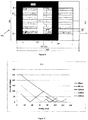
- Figure 7 shows the explicit uncompensated power contributions of each of the receiver coils that make up the BPRP when it is positioned 250mm vertically above the DDP transmitter of Figure 1 (configured as in Table A1) but shifted laterally in either the x or y directions.
- the output of each of these coils is indicated by use of labels A and B respectively (where A represents the coil on the left of Figure 4 and B represents the coil on the right of Figure 4 ).
- the contributions are identical when the pad is shifted in the y direction as each of the receiver coils are equidistant from the DDP transmitter.
- receiver coil B When shifted in the positive x direction, then receiver coil B is shifted further away from the transmitter and therefore captures less flux, while coil A captures a greater percentage of the available flux. If the BPRP were shifted in the opposite negative x direction, then the flux capture would naturally reverse.
- the DDQP pickup has two sets of coils, 2, 3 (DD) (assuming the two DD coils are in series) and the quadrature (Q) coil 12.
- DD DD
- Q quadrature
- the BPRP has a power profile which is almost identical for the majority of the useable offset range. It requires 17% more copper that the DDP, but the DDQP uses 56% more copper that the DDP. In consequence the DDQP uses 34% more copper than the BPRP and only produces slightly improved power profile in the x direction (perhaps 20-25% improvement at best at 200-250mm offset)
- Table A1 Dimensions of the transmitter DDP Winding width 84 mm Inner winding width 84mm Ferrite spacing 33 mm Ferrite width 28 mm Y coil spacing 10 mm Y padding 0 mm Cover thickness 6 mm Coil height 4 mm Ferrite height 16 mm Spacer thickness 6 mm Plate thickness 4 mm Ferrite length 651 mm X coil spacing (csX) 10 mm X padding 0 mm
- Table A2 Dimensions of the receiver DDP and DDQP Winding width 84 mm Inner winding width 84mm Ferrite spacing 33 mm Ferrite width 28 mm Y coil spacing 10 mm Y padding 0 mm Cover thickness 6 mm Coil height 4 mm Ferrite height 16 mm Spacer thickness 6 mm Plate thickness 4 mm Ferrite length 837 mm X coil spacing (csX) - 80
- the flux receiver construction described herein can also be used to sense the presence and alignment of the receiver with a transmitter.
- the transmitter may have a similar construction to the receiver, but could be a different construction, for example the transmitter could be a circular single coil pad structure such as that disclosed in WO2008/140333 .
- the extent of alignment (or misalignment) is detected by activating decoupling switch 809 and sensing the magnitude and phase of the AC short circuit current in one of coils 2, 3 with respect to the other, , whereas in applications where the coils are series tuned the extent of alignment (or misalignment) can be determined by again decoupling both receiver coils and measuring the magnitude and phase of the open circuit voltage of coils 2 and 3.
- the magnetic assembly describes two overlapping coils which preferably are substantially mutually decoupled, it will be apparent to those skilled in the art, that in some instances it may be helpful to have overlapping coils which are not substantially mutually decoupled. For example, it may be desirable to make the coils wider and therefore the overlap is larger than necessary. In such instances the combined power received from both coils 2 and 3 when the receiver is ideally aligned with a suitable transmitter will be less than if they were designed to be mutually decoupled, however because coils 2 and 3 are made wider they can better capture the available flux when the receiver is displaced laterally from a suitable transmitter and this may be an advantage in some designs to help improve tolerance to misalignment.
- the coils are preferably made from litz wire.
- litz wire manufactured from aluminium (rather than the conventional copper) offers significant unexpected advantages. Aluminium has previously been considered to be unsuitable because it is very fragile and it cannot be soldered to make terminations. However, we have found that it can be manufactured as Litz wire from individual strands of 0.3mm diameter and in such a form is lighter and provides up to approximately seven times as much useful wire as copper for a comparable cost. Aluminium Litz wire can be used in other flux generating and receiving magnetic structures which include the pad structures described in this document and others including without limitation the circular pads referred to in WO2008/140333 for example. Aluminium can also be used as copper clad alumium which can be drawn to size, and assembled if desired to provide litz wire. It can thus be soldered, and is about 75% lighter than conventional copper wire while being able to be used essentially as a conventional wire as well as litz wire.
Landscapes
- Engineering & Computer Science (AREA)
- Power Engineering (AREA)
- Computer Networks & Wireless Communication (AREA)
- Physics & Mathematics (AREA)
- Electromagnetism (AREA)
- Manufacturing & Machinery (AREA)
- Current-Collector Devices For Electrically Propelled Vehicles (AREA)
- Electric Propulsion And Braking For Vehicles (AREA)
- Charge And Discharge Circuits For Batteries Or The Like (AREA)
- Transportation (AREA)
- Mechanical Engineering (AREA)
Claims (12)
- Magnetflusspad zum Empfangen eines magnetischen Flusses, wobei das Pad einen magnetisch permeablen Kern (4) und zwei überlappende, im Wesentlichen koplanare Spulen (2, 3) umfasst, die magnetisch mit dem Kern (4) assoziiert sind, wobei eine Überlappung zwischen den Spulen (2, 3) derart ist, dass es keine gemeinsame Kopplung zwischen den Spulen (2, 3) gibt, wobei das Flusspad eine Einrichtung beinhaltet, die zum unabhängigen Abstimmen jeder Spule (2, 3) und Kombinieren der Ausgabe jeder abgestimmten Spule (2, 3) eingerichtet ist, um dadurch Leistung bereitzustellen.
- Magnetflusspad nach Anspruch 1, wobei die magnetischen Eigenschaften der Spulen (2, 3) gleich sind.
- Magnetflusspad nach einem der vorhergehenden Ansprüche, wobei eine Überlappung zwischen den Spulen (2, 3) derart ist, dass die Spulen vollständig magnetisch entkoppelt sind.
- Magnetflusspad nach einem der vorhergehenden Ansprüche, wobei die Spulen (2, 3) teilweise überlappen.
- Magnetflusspad nach einem der vorhergehenden Ansprüche, wobei die Spulen (2, 3) flach sind.
- Magnetflusspad nach einem der vorhergehenden Ansprüche, wobei die Spulen (2, 3) auf einer Seite des permeablen Kerns (4) bereitgestellt sind und ein Abschirmungsmittel auf der anderen Seite des Kerns (4) bereitgestellt ist.
- Magnetflusspad nach Anspruch 6, wobei das Abschirmungsmittel eine Abschirmungsplatte umfasst.
- Magnetflusspad nach Anspruch 7, wobei die Abschirmungsplatte aus Aluminium oder Magnesium gefertigt ist.
- Magnetflusspad nach einem der vorhergehenden Ansprüche, wobei eine dielektrische Abdeckung auf der Seite der Spulen (2, 3) gegenüber dem Magnetkern (2, 3) bereitgestellt ist.
- Aufnahmeeinrichtung für ein induktives Leistungstransfersystem, wobei die Aufnahmeeinrichtung Folgendes beinhaltet:
ein Magnetflusspad nach einem vorhergehenden Anspruch, wobei die kombinierte Ausgabe jeder abgestimmten Spule (2, 3) Leistung an einen Ausgang der Aufnahmeeinrichtung liefert. - Aufnahmeeinrichtung nach Anspruch 10, die ferner Schaltmittel zum Regeln der an dem Ausgang verfügbaren Leistung beinhaltet.
- Aufnahmeeinrichtung nach Anspruch 10 oder 11, die ferner Detektionsmittel zum Detektieren der Ausrichtung des Magnetflusspads der Aufnahme mit einem Transmitterflusspad detektiert.
Applications Claiming Priority (3)
| Application Number | Priority Date | Filing Date | Title |
|---|---|---|---|
| PCT/NZ2010/000160 WO2011016737A1 (en) | 2009-08-07 | 2010-08-06 | Inductive power transfer system |
| NZ58893710 | 2010-11-01 | ||
| PCT/NZ2011/000154 WO2012018269A1 (en) | 2010-08-06 | 2011-08-05 | Inductive power receiver apparatus |
Publications (3)
| Publication Number | Publication Date |
|---|---|
| EP2601723A1 EP2601723A1 (de) | 2013-06-12 |
| EP2601723A4 EP2601723A4 (de) | 2017-08-16 |
| EP2601723B1 true EP2601723B1 (de) | 2020-04-22 |
Family
ID=45559668
Family Applications (1)
| Application Number | Title | Priority Date | Filing Date |
|---|---|---|---|
| EP11814854.3A Active EP2601723B1 (de) | 2010-08-06 | 2011-08-05 | Induktive stromempfangsvorrichtung |
Country Status (6)
| Country | Link |
|---|---|
| US (2) | US9620281B2 (de) |
| EP (1) | EP2601723B1 (de) |
| JP (1) | JP5941046B2 (de) |
| KR (2) | KR101825627B1 (de) |
| CN (2) | CN109585147B (de) |
| WO (1) | WO2012018269A1 (de) |
Families Citing this family (35)
| Publication number | Priority date | Publication date | Assignee | Title |
|---|---|---|---|---|
| JP2013501665A (ja) | 2009-08-07 | 2013-01-17 | オークランド ユニサービシズ リミテッド | 道路から電気エネルギーを得る電気車両システム |
| US9620281B2 (en) * | 2010-08-06 | 2017-04-11 | Auckland Uniservices Limited | Inductive power receiver apparatus |
| JP6294831B2 (ja) * | 2011-12-16 | 2018-03-14 | オークランド ユニサービシズ リミテッドAuckland Uniservices Limited | 誘導電力伝送システムおよび方法 |
| US20150236513A1 (en) * | 2012-02-16 | 2015-08-20 | Auckland Uniservices Limited | Multiple coil flux pad |
| US9666357B2 (en) * | 2012-09-11 | 2017-05-30 | Qualcomm Incorporated | Apparatus system, and method for wirelessly receiving power using conductive structures |
| US10014104B2 (en) | 2012-11-02 | 2018-07-03 | Qualcomm Incorporated | Coil arrangements in wireless power transfer systems for low electromagnetic emissions |
| US9142990B2 (en) | 2013-01-18 | 2015-09-22 | Qualcomm Incorporated | Method of multi-coil operation and optimization |
| US10573445B2 (en) | 2013-03-27 | 2020-02-25 | Auckland Uniservices Limited | Electromagnetic field confinement |
| JP2015015452A (ja) * | 2013-06-06 | 2015-01-22 | Tdk株式会社 | ワイヤレス電力伝送用コイル装置 |
| WO2015132890A1 (ja) * | 2014-03-04 | 2015-09-11 | 株式会社 テクノバ | 走行中非接触給電システム |
| KR20170031128A (ko) * | 2014-07-09 | 2017-03-20 | 오클랜드 유니서비시즈 리미티드 | 전기 차량들에 적절한 유도 전력 시스템 |
| US11031826B2 (en) | 2014-09-11 | 2021-06-08 | Auckland Uniservices Limited | Magnetic flux coupling structures with controlled flux cancellation |
| US9941708B2 (en) | 2014-11-05 | 2018-04-10 | Qualcomm Incorporated | Systems, methods, and apparatus for integrated tuning capacitors in charging coil structure |
| US10414279B2 (en) * | 2014-12-19 | 2019-09-17 | Ford Global Technologies, Llc | Inductive wireless power transfer systems |
| US9991732B2 (en) | 2015-04-10 | 2018-06-05 | Enovate Medical Llc | Contactless battery system utilizing a bidirectional power converter |
| US9935501B2 (en) * | 2015-04-10 | 2018-04-03 | Samsung Electro-Mechanics Co., Ltd. | Wireless power transmitting and receiving device, apparatus including the same, and method |
| CN108141063B (zh) | 2015-08-06 | 2022-06-28 | 奥克兰大学服务有限公司 | 混合感应电力传输系统 |
| US9876366B2 (en) | 2015-09-25 | 2018-01-23 | Qualcomm Incorporated | Methods and apparatus utilizing a bipolar double D vehicle coupler in wireless power transfer applications |
| US20170229913A1 (en) * | 2016-02-08 | 2017-08-10 | Qualcomm Incorporated | Wireless power transfer in wearable devices |
| WO2017156499A1 (en) * | 2016-03-10 | 2017-09-14 | Wireless Advanced Vehicle Electrification, Inc. | Bi-plane wireless power transmission pad |
| US10756572B2 (en) | 2016-05-20 | 2020-08-25 | Lear Corporation | Wireless charging pad having coolant assembly |
| US11237595B2 (en) | 2016-06-06 | 2022-02-01 | Omnicharge, Inc. | Portable power solutions |
| US10630085B2 (en) * | 2016-06-06 | 2020-04-21 | Omnicharge, Inc. | Portable power solutions |
| US11376966B2 (en) | 2016-07-19 | 2022-07-05 | Auckland Uniservices Limited | Electric vehicle detection for roadway wireless power transfer |
| US10958111B2 (en) | 2016-08-01 | 2021-03-23 | Auckland Uniservices Limited | Power transfer and leakage flux control |
| US10245963B2 (en) | 2016-12-05 | 2019-04-02 | Lear Corporation | Air cooled wireless charging pad |
| KR20180115932A (ko) * | 2017-04-14 | 2018-10-24 | 엘지이노텍 주식회사 | 중첩되어 배치되는 복수의 무선 전력 안테나를 포함하는 무선 전력 송신기 |
| WO2019108071A1 (en) | 2017-12-01 | 2019-06-06 | Auckland Uniservices Limited | A misalignment tolerant hybrid wireless power transfer system |
| CN108461264B (zh) * | 2018-02-09 | 2020-03-03 | 浙江大学 | 一种偏移容错范围大的无线电能传输松散磁耦合变压器装置及其电路 |
| JP7275648B2 (ja) * | 2018-06-26 | 2023-05-18 | 株式会社デンソー | 走行中非接触給電システム |
| WO2020159323A1 (ko) * | 2019-02-01 | 2020-08-06 | 주식회사 와이파워원 | 전기차량 및 산업용 장비의 주행 중 무선충전 급전 시스템 |
| US11394242B2 (en) | 2019-09-12 | 2022-07-19 | Spark Connected LLC | Wireless power transfer in-band communication circuit and method |
| US11837884B2 (en) | 2020-12-17 | 2023-12-05 | Tennessee Technological University | Layered double-D coil for wireless power transfer systems |
| CN115149666A (zh) * | 2021-03-31 | 2022-10-04 | 欧姆龙株式会社 | 无线充电系统、发射侧充电装置和接收侧充电装置 |
| US12523654B1 (en) * | 2022-08-22 | 2026-01-13 | National Technology & Engineering Solutions Of Sandia, Llc | Multiplanar planar electromagnetic array |
Citations (1)
| Publication number | Priority date | Publication date | Assignee | Title |
|---|---|---|---|---|
| US4973907A (en) * | 1988-12-01 | 1990-11-27 | U.S. Philips Corporation | RF coil system having several surface coils |
Family Cites Families (31)
| Publication number | Priority date | Publication date | Assignee | Title |
|---|---|---|---|---|
| JP3163967B2 (ja) * | 1995-10-19 | 2001-05-08 | 住友電装株式会社 | 電気自動車充電用の電磁結合装置 |
| US6556013B2 (en) * | 2001-03-09 | 2003-04-29 | Bruker Biospin Corp. | Planar NMR coils with localized field-generating and capacitive elements |
| CN1171557C (zh) * | 2001-05-30 | 2004-10-20 | 陈梓平 | 一种用于电磁炉具上的带电磁耦合线圈的烹调器具 |
| GB2388716B (en) * | 2002-05-13 | 2004-10-20 | Splashpower Ltd | Improvements relating to contact-less power transfer |
| GB0210886D0 (en) * | 2002-05-13 | 2002-06-19 | Zap Wireless Technologies Ltd | Improvements relating to contact-less power transfer |
| US7180403B2 (en) * | 2004-05-18 | 2007-02-20 | Assa Abloy Identification Technology Group Ab | RFID reader utilizing an analog to digital converter for data acquisition and power monitoring functions |
| JP4852829B2 (ja) * | 2004-07-28 | 2012-01-11 | セイコーエプソン株式会社 | 非接触電力伝送装置 |
| US20080224656A1 (en) * | 2005-09-12 | 2008-09-18 | Koninklijke Philips Electronics, N.V. | Device For Recharging Batteries |
| US7952322B2 (en) * | 2006-01-31 | 2011-05-31 | Mojo Mobility, Inc. | Inductive power source and charging system |
| US8169185B2 (en) * | 2006-01-31 | 2012-05-01 | Mojo Mobility, Inc. | System and method for inductive charging of portable devices |
| NZ546955A (en) * | 2006-05-02 | 2008-09-26 | Auckland Uniservices Ltd | Pick-up apparatus for inductive power transfer systems |
| NZ547604A (en) | 2006-05-30 | 2008-09-26 | John Talbot Boys | Inductive power transfer system pick-up circuit |
| US9520225B2 (en) * | 2006-09-18 | 2016-12-13 | Koninklijke Philips N.V. | Apparatus, a system and a method for enabling electromagnetic energy transfer |
| JP4936923B2 (ja) * | 2007-02-20 | 2012-05-23 | 株式会社東芝 | 静止誘導機器および静止誘導機器監視装置 |
| WO2008140333A2 (en) * | 2007-05-10 | 2008-11-20 | Auckland Uniservices Limited | Multi power sourced electric vehicle |
| KR20100017582A (ko) * | 2007-05-10 | 2010-02-16 | 오클랜드 유니서비시즈 리미티드 | 멀티 전력을 공급받는 전기 자동차 |
| KR20100054846A (ko) * | 2007-09-28 | 2010-05-25 | 액세스 비지니스 그룹 인터내셔날 엘엘씨 | 다중 위상 유도 전력 공급 시스템 |
| JP5224442B2 (ja) * | 2007-12-28 | 2013-07-03 | Necトーキン株式会社 | 非接触電力伝送装置 |
| JP2010022183A (ja) * | 2008-02-08 | 2010-01-28 | Suri-Ai:Kk | 電気自動車及びそれに好適な車両用誘導送電装置 |
| JP2009200174A (ja) * | 2008-02-20 | 2009-09-03 | Panasonic Electric Works Co Ltd | 非接触電力伝送機器 |
| JP2010041906A (ja) * | 2008-07-10 | 2010-02-18 | Nec Tokin Corp | 非接触電力伝送装置、軟磁性体シート及びそれを用いたモジュール |
| JP2012504387A (ja) * | 2008-09-27 | 2012-02-16 | ウィトリシティ コーポレーション | 無線エネルギー伝達システム |
| US20120119698A1 (en) * | 2008-09-27 | 2012-05-17 | Aristeidis Karalis | Wireless energy transfer for vehicles |
| JP5439797B2 (ja) * | 2008-11-20 | 2014-03-12 | パナソニック株式会社 | ノイズフィルタ |
| CN101447699A (zh) * | 2008-12-31 | 2009-06-03 | 湖南大学 | 高压输电线在线除冰机器人的电磁感应耦合电源装置 |
| CA2751595C (en) * | 2009-02-05 | 2023-08-01 | Auckland Uniservices Limited | Inductive power transfer apparatus |
| JP2013501665A (ja) * | 2009-08-07 | 2013-01-17 | オークランド ユニサービシズ リミテッド | 道路から電気エネルギーを得る電気車両システム |
| CN201523069U (zh) * | 2009-10-28 | 2010-07-07 | 北京握奇数据系统有限公司 | 一种非接触式天线、天线组、智能卡和终端设备 |
| JP6144195B2 (ja) * | 2010-05-19 | 2017-07-12 | オークランド ユニサービシズ リミテッドAuckland Uniservices Limited | 誘導電力転送システム1次トラックトポロジー |
| KR101134625B1 (ko) * | 2010-07-16 | 2012-04-09 | 주식회사 한림포스텍 | 무선 전력 통신용 코어 어셈블리와 그를 구비하는 무선 전력 통신용 전력 공급 장치, 그리고 무선 전력 통신용 코어 어셈블리 제조 방법 |
| US9620281B2 (en) * | 2010-08-06 | 2017-04-11 | Auckland Uniservices Limited | Inductive power receiver apparatus |
-
2011
- 2011-08-05 US US13/814,542 patent/US9620281B2/en active Active
- 2011-08-05 WO PCT/NZ2011/000154 patent/WO2012018269A1/en not_active Ceased
- 2011-08-05 KR KR1020137005726A patent/KR101825627B1/ko active Active
- 2011-08-05 EP EP11814854.3A patent/EP2601723B1/de active Active
- 2011-08-05 CN CN201811263929.8A patent/CN109585147B/zh active Active
- 2011-08-05 JP JP2013524060A patent/JP5941046B2/ja active Active
- 2011-08-05 KR KR1020187002898A patent/KR101970324B1/ko active Active
- 2011-08-05 CN CN2011800480573A patent/CN103155341A/zh active Pending
-
2017
- 2017-04-10 US US15/483,838 patent/US10424967B2/en active Active
Patent Citations (1)
| Publication number | Priority date | Publication date | Assignee | Title |
|---|---|---|---|---|
| US4973907A (en) * | 1988-12-01 | 1990-11-27 | U.S. Philips Corporation | RF coil system having several surface coils |
Also Published As
| Publication number | Publication date |
|---|---|
| WO2012018269A1 (en) | 2012-02-09 |
| CN109585147B (zh) | 2023-10-31 |
| KR20130093616A (ko) | 2013-08-22 |
| JP2013535841A (ja) | 2013-09-12 |
| US9620281B2 (en) | 2017-04-11 |
| CN103155341A (zh) | 2013-06-12 |
| KR20180015752A (ko) | 2018-02-13 |
| JP5941046B2 (ja) | 2016-06-29 |
| EP2601723A4 (de) | 2017-08-16 |
| US20130285463A1 (en) | 2013-10-31 |
| EP2601723A1 (de) | 2013-06-12 |
| US20170222485A1 (en) | 2017-08-03 |
| US10424967B2 (en) | 2019-09-24 |
| CN109585147A (zh) | 2019-04-05 |
| KR101970324B1 (ko) | 2019-04-18 |
| KR101825627B1 (ko) | 2018-03-22 |
Similar Documents
| Publication | Publication Date | Title |
|---|---|---|
| EP2601723B1 (de) | Induktive stromempfangsvorrichtung | |
| US11581124B2 (en) | Multiple coil flux pad | |
| EP2462679B1 (de) | Induktives stromübertragungssystem | |
| KR101948276B1 (ko) | 유도 전력 전송 장치 | |
| US11756727B2 (en) | Wireless power transfer coupling structures with reduced leakage flux | |
| NZ609482A (en) | Multiple coil flux pad | |
| NZ609482B2 (en) | Multiple coil flux pad |
Legal Events
| Date | Code | Title | Description |
|---|---|---|---|
| PUAI | Public reference made under article 153(3) epc to a published international application that has entered the european phase |
Free format text: ORIGINAL CODE: 0009012 |
|
| 17P | Request for examination filed |
Effective date: 20130306 |
|
| AK | Designated contracting states |
Kind code of ref document: A1 Designated state(s): AL AT BE BG CH CY CZ DE DK EE ES FI FR GB GR HR HU IE IS IT LI LT LU LV MC MK MT NL NO PL PT RO RS SE SI SK SM TR |
|
| DAX | Request for extension of the european patent (deleted) | ||
| RA4 | Supplementary search report drawn up and despatched (corrected) |
Effective date: 20170713 |
|
| RIC1 | Information provided on ipc code assigned before grant |
Ipc: H02J 7/00 20060101AFI20170707BHEP |
|
| 111L | Licence recorded |
Designated state(s): AL AT BE BG CH CY CZ DE DK EE ES FI FR GB GR HR HU IE IS IT LT LU LV MC MK MT NL NO PL PT RO RS SE SI SK SM TR Free format text: EXCLUSIVE LICENSE Name of requester: QUALCOMM INCORPORATED, US Effective date: 20171018 |
|
| STAA | Information on the status of an ep patent application or granted ep patent |
Free format text: STATUS: REQUEST FOR EXAMINATION WAS MADE |
|
| STAA | Information on the status of an ep patent application or granted ep patent |
Free format text: STATUS: EXAMINATION IS IN PROGRESS |
|
| 17Q | First examination report despatched |
Effective date: 20180712 |
|
| RAP1 | Party data changed (applicant data changed or rights of an application transferred) |
Owner name: AUCKLAND UNISERVICES LIMITED |
|
| GRAP | Despatch of communication of intention to grant a patent |
Free format text: ORIGINAL CODE: EPIDOSNIGR1 |
|
| STAA | Information on the status of an ep patent application or granted ep patent |
Free format text: STATUS: GRANT OF PATENT IS INTENDED |
|
| INTG | Intention to grant announced |
Effective date: 20191218 |
|
| GRAS | Grant fee paid |
Free format text: ORIGINAL CODE: EPIDOSNIGR3 |
|
| GRAA | (expected) grant |
Free format text: ORIGINAL CODE: 0009210 |
|
| STAA | Information on the status of an ep patent application or granted ep patent |
Free format text: STATUS: THE PATENT HAS BEEN GRANTED |
|
| 111L | Licence recorded |
Designated state(s): AL AT BE BG CH CY CZ DE DK EE ES FI FR GB GR HR HU IE IS IT LT LU LV MC MK MT NL NO PL PT RO RS SE SI SK SM TR Free format text: EXCLUSIVE LICENSE Name of requester: QUALCOMM INCORPORATED, US Effective date: 20171018 |
|
| AK | Designated contracting states |
Kind code of ref document: B1 Designated state(s): AL AT BE BG CH CY CZ DE DK EE ES FI FR GB GR HR HU IE IS IT LI LT LU LV MC MK MT NL NO PL PT RO RS SE SI SK SM TR |
|
| REG | Reference to a national code |
Ref country code: GB Ref legal event code: FG4D |
|
| REG | Reference to a national code |
Ref country code: CH Ref legal event code: EP |
|
| REG | Reference to a national code |
Ref country code: IE Ref legal event code: FG4D |
|
| REG | Reference to a national code |
Ref country code: DE Ref legal event code: R096 Ref document number: 602011066420 Country of ref document: DE |
|
| REG | Reference to a national code |
Ref country code: AT Ref legal event code: REF Ref document number: 1261421 Country of ref document: AT Kind code of ref document: T Effective date: 20200515 |
|
| REG | Reference to a national code |
Ref country code: LT Ref legal event code: MG4D |
|
| REG | Reference to a national code |
Ref country code: NL Ref legal event code: MP Effective date: 20200422 |
|
| PG25 | Lapsed in a contracting state [announced via postgrant information from national office to epo] |
Ref country code: LT Free format text: LAPSE BECAUSE OF FAILURE TO SUBMIT A TRANSLATION OF THE DESCRIPTION OR TO PAY THE FEE WITHIN THE PRESCRIBED TIME-LIMIT Effective date: 20200422 Ref country code: FI Free format text: LAPSE BECAUSE OF FAILURE TO SUBMIT A TRANSLATION OF THE DESCRIPTION OR TO PAY THE FEE WITHIN THE PRESCRIBED TIME-LIMIT Effective date: 20200422 Ref country code: GR Free format text: LAPSE BECAUSE OF FAILURE TO SUBMIT A TRANSLATION OF THE DESCRIPTION OR TO PAY THE FEE WITHIN THE PRESCRIBED TIME-LIMIT Effective date: 20200723 Ref country code: NO Free format text: LAPSE BECAUSE OF FAILURE TO SUBMIT A TRANSLATION OF THE DESCRIPTION OR TO PAY THE FEE WITHIN THE PRESCRIBED TIME-LIMIT Effective date: 20200722 Ref country code: SE Free format text: LAPSE BECAUSE OF FAILURE TO SUBMIT A TRANSLATION OF THE DESCRIPTION OR TO PAY THE FEE WITHIN THE PRESCRIBED TIME-LIMIT Effective date: 20200422 Ref country code: IS Free format text: LAPSE BECAUSE OF FAILURE TO SUBMIT A TRANSLATION OF THE DESCRIPTION OR TO PAY THE FEE WITHIN THE PRESCRIBED TIME-LIMIT Effective date: 20200822 Ref country code: PT Free format text: LAPSE BECAUSE OF FAILURE TO SUBMIT A TRANSLATION OF THE DESCRIPTION OR TO PAY THE FEE WITHIN THE PRESCRIBED TIME-LIMIT Effective date: 20200824 Ref country code: NL Free format text: LAPSE BECAUSE OF FAILURE TO SUBMIT A TRANSLATION OF THE DESCRIPTION OR TO PAY THE FEE WITHIN THE PRESCRIBED TIME-LIMIT Effective date: 20200422 |
|
| REG | Reference to a national code |
Ref country code: AT Ref legal event code: MK05 Ref document number: 1261421 Country of ref document: AT Kind code of ref document: T Effective date: 20200422 |
|
| PG25 | Lapsed in a contracting state [announced via postgrant information from national office to epo] |
Ref country code: LV Free format text: LAPSE BECAUSE OF FAILURE TO SUBMIT A TRANSLATION OF THE DESCRIPTION OR TO PAY THE FEE WITHIN THE PRESCRIBED TIME-LIMIT Effective date: 20200422 Ref country code: RS Free format text: LAPSE BECAUSE OF FAILURE TO SUBMIT A TRANSLATION OF THE DESCRIPTION OR TO PAY THE FEE WITHIN THE PRESCRIBED TIME-LIMIT Effective date: 20200422 Ref country code: HR Free format text: LAPSE BECAUSE OF FAILURE TO SUBMIT A TRANSLATION OF THE DESCRIPTION OR TO PAY THE FEE WITHIN THE PRESCRIBED TIME-LIMIT Effective date: 20200422 Ref country code: BG Free format text: LAPSE BECAUSE OF FAILURE TO SUBMIT A TRANSLATION OF THE DESCRIPTION OR TO PAY THE FEE WITHIN THE PRESCRIBED TIME-LIMIT Effective date: 20200722 |
|
| PG25 | Lapsed in a contracting state [announced via postgrant information from national office to epo] |
Ref country code: AL Free format text: LAPSE BECAUSE OF FAILURE TO SUBMIT A TRANSLATION OF THE DESCRIPTION OR TO PAY THE FEE WITHIN THE PRESCRIBED TIME-LIMIT Effective date: 20200422 |
|
| REG | Reference to a national code |
Ref country code: DE Ref legal event code: R097 Ref document number: 602011066420 Country of ref document: DE |
|
| PG25 | Lapsed in a contracting state [announced via postgrant information from national office to epo] |
Ref country code: CZ Free format text: LAPSE BECAUSE OF FAILURE TO SUBMIT A TRANSLATION OF THE DESCRIPTION OR TO PAY THE FEE WITHIN THE PRESCRIBED TIME-LIMIT Effective date: 20200422 Ref country code: IT Free format text: LAPSE BECAUSE OF FAILURE TO SUBMIT A TRANSLATION OF THE DESCRIPTION OR TO PAY THE FEE WITHIN THE PRESCRIBED TIME-LIMIT Effective date: 20200422 Ref country code: DK Free format text: LAPSE BECAUSE OF FAILURE TO SUBMIT A TRANSLATION OF THE DESCRIPTION OR TO PAY THE FEE WITHIN THE PRESCRIBED TIME-LIMIT Effective date: 20200422 Ref country code: SM Free format text: LAPSE BECAUSE OF FAILURE TO SUBMIT A TRANSLATION OF THE DESCRIPTION OR TO PAY THE FEE WITHIN THE PRESCRIBED TIME-LIMIT Effective date: 20200422 Ref country code: AT Free format text: LAPSE BECAUSE OF FAILURE TO SUBMIT A TRANSLATION OF THE DESCRIPTION OR TO PAY THE FEE WITHIN THE PRESCRIBED TIME-LIMIT Effective date: 20200422 Ref country code: EE Free format text: LAPSE BECAUSE OF FAILURE TO SUBMIT A TRANSLATION OF THE DESCRIPTION OR TO PAY THE FEE WITHIN THE PRESCRIBED TIME-LIMIT Effective date: 20200422 Ref country code: ES Free format text: LAPSE BECAUSE OF FAILURE TO SUBMIT A TRANSLATION OF THE DESCRIPTION OR TO PAY THE FEE WITHIN THE PRESCRIBED TIME-LIMIT Effective date: 20200422 Ref country code: RO Free format text: LAPSE BECAUSE OF FAILURE TO SUBMIT A TRANSLATION OF THE DESCRIPTION OR TO PAY THE FEE WITHIN THE PRESCRIBED TIME-LIMIT Effective date: 20200422 |
|
| PG25 | Lapsed in a contracting state [announced via postgrant information from national office to epo] |
Ref country code: SK Free format text: LAPSE BECAUSE OF FAILURE TO SUBMIT A TRANSLATION OF THE DESCRIPTION OR TO PAY THE FEE WITHIN THE PRESCRIBED TIME-LIMIT Effective date: 20200422 Ref country code: PL Free format text: LAPSE BECAUSE OF FAILURE TO SUBMIT A TRANSLATION OF THE DESCRIPTION OR TO PAY THE FEE WITHIN THE PRESCRIBED TIME-LIMIT Effective date: 20200422 |
|
| PLBE | No opposition filed within time limit |
Free format text: ORIGINAL CODE: 0009261 |
|
| STAA | Information on the status of an ep patent application or granted ep patent |
Free format text: STATUS: NO OPPOSITION FILED WITHIN TIME LIMIT |
|
| 26N | No opposition filed |
Effective date: 20210125 |
|
| PG25 | Lapsed in a contracting state [announced via postgrant information from national office to epo] |
Ref country code: MC Free format text: LAPSE BECAUSE OF FAILURE TO SUBMIT A TRANSLATION OF THE DESCRIPTION OR TO PAY THE FEE WITHIN THE PRESCRIBED TIME-LIMIT Effective date: 20200422 |
|
| REG | Reference to a national code |
Ref country code: CH Ref legal event code: PL |
|
| PG25 | Lapsed in a contracting state [announced via postgrant information from national office to epo] |
Ref country code: LU Free format text: LAPSE BECAUSE OF NON-PAYMENT OF DUE FEES Effective date: 20200805 Ref country code: CH Free format text: LAPSE BECAUSE OF NON-PAYMENT OF DUE FEES Effective date: 20200831 Ref country code: LI Free format text: LAPSE BECAUSE OF NON-PAYMENT OF DUE FEES Effective date: 20200831 |
|
| REG | Reference to a national code |
Ref country code: BE Ref legal event code: MM Effective date: 20200831 |
|
| PG25 | Lapsed in a contracting state [announced via postgrant information from national office to epo] |
Ref country code: SI Free format text: LAPSE BECAUSE OF FAILURE TO SUBMIT A TRANSLATION OF THE DESCRIPTION OR TO PAY THE FEE WITHIN THE PRESCRIBED TIME-LIMIT Effective date: 20200422 |
|
| PG25 | Lapsed in a contracting state [announced via postgrant information from national office to epo] |
Ref country code: BE Free format text: LAPSE BECAUSE OF NON-PAYMENT OF DUE FEES Effective date: 20200831 Ref country code: IE Free format text: LAPSE BECAUSE OF NON-PAYMENT OF DUE FEES Effective date: 20200805 |
|
| PG25 | Lapsed in a contracting state [announced via postgrant information from national office to epo] |
Ref country code: TR Free format text: LAPSE BECAUSE OF FAILURE TO SUBMIT A TRANSLATION OF THE DESCRIPTION OR TO PAY THE FEE WITHIN THE PRESCRIBED TIME-LIMIT Effective date: 20200422 Ref country code: MT Free format text: LAPSE BECAUSE OF FAILURE TO SUBMIT A TRANSLATION OF THE DESCRIPTION OR TO PAY THE FEE WITHIN THE PRESCRIBED TIME-LIMIT Effective date: 20200422 Ref country code: CY Free format text: LAPSE BECAUSE OF FAILURE TO SUBMIT A TRANSLATION OF THE DESCRIPTION OR TO PAY THE FEE WITHIN THE PRESCRIBED TIME-LIMIT Effective date: 20200422 |
|
| PG25 | Lapsed in a contracting state [announced via postgrant information from national office to epo] |
Ref country code: MK Free format text: LAPSE BECAUSE OF FAILURE TO SUBMIT A TRANSLATION OF THE DESCRIPTION OR TO PAY THE FEE WITHIN THE PRESCRIBED TIME-LIMIT Effective date: 20200422 |
|
| P01 | Opt-out of the competence of the unified patent court (upc) registered |
Effective date: 20230529 |
|
| PGFP | Annual fee paid to national office [announced via postgrant information from national office to epo] |
Ref country code: DE Payment date: 20250708 Year of fee payment: 15 |
|
| PGFP | Annual fee paid to national office [announced via postgrant information from national office to epo] |
Ref country code: GB Payment date: 20250707 Year of fee payment: 15 |
|
| PGFP | Annual fee paid to national office [announced via postgrant information from national office to epo] |
Ref country code: FR Payment date: 20250707 Year of fee payment: 15 |