EP2601871B1 - Abnehmbarer Griff und Kochutensil für einen solchen Griff - Google Patents
Abnehmbarer Griff und Kochutensil für einen solchen Griff Download PDFInfo
- Publication number
- EP2601871B1 EP2601871B1 EP20120290425 EP12290425A EP2601871B1 EP 2601871 B1 EP2601871 B1 EP 2601871B1 EP 20120290425 EP20120290425 EP 20120290425 EP 12290425 A EP12290425 A EP 12290425A EP 2601871 B1 EP2601871 B1 EP 2601871B1
- Authority
- EP
- European Patent Office
- Prior art keywords
- handle
- base
- movable magnet
- intended
- locking
- Prior art date
- Legal status (The legal status is an assumption and is not a legal conclusion. Google has not performed a legal analysis and makes no representation as to the accuracy of the status listed.)
- Not-in-force
Links
- 238000010411 cooking Methods 0.000 title description 2
- 230000007246 mechanism Effects 0.000 claims description 17
- 230000008878 coupling Effects 0.000 claims description 5
- 238000010168 coupling process Methods 0.000 claims description 5
- 238000005859 coupling reaction Methods 0.000 claims description 5
- 230000002093 peripheral effect Effects 0.000 claims description 3
- 238000000926 separation method Methods 0.000 description 4
- 238000006073 displacement reaction Methods 0.000 description 2
- 230000000694 effects Effects 0.000 description 2
- 229910001220 stainless steel Inorganic materials 0.000 description 2
- 239000010935 stainless steel Substances 0.000 description 2
- 230000007704 transition Effects 0.000 description 2
- 229920001342 Bakelite® Polymers 0.000 description 1
- 239000000919 ceramic Substances 0.000 description 1
- 239000003795 chemical substances by application Substances 0.000 description 1
- 238000010586 diagram Methods 0.000 description 1
- 239000011521 glass Substances 0.000 description 1
- 239000000463 material Substances 0.000 description 1
- 239000002184 metal Substances 0.000 description 1
- 239000002991 molded plastic Substances 0.000 description 1
- 229920001568 phenolic resin Polymers 0.000 description 1
- 239000004033 plastic Substances 0.000 description 1
- 229920003023 plastic Polymers 0.000 description 1
- 230000000750 progressive effect Effects 0.000 description 1
Images


Classifications
-
- A—HUMAN NECESSITIES
- A47—FURNITURE; DOMESTIC ARTICLES OR APPLIANCES; COFFEE MILLS; SPICE MILLS; SUCTION CLEANERS IN GENERAL
- A47J—KITCHEN EQUIPMENT; COFFEE MILLS; SPICE MILLS; APPARATUS FOR MAKING BEVERAGES
- A47J45/00—Devices for fastening or gripping kitchen utensils or crockery
- A47J45/06—Handles for hollow-ware articles
- A47J45/07—Handles for hollow-ware articles of detachable type
- A47J45/071—Saucepan, frying-pan handles
Definitions
- the invention relates to kitchen utensils, such as pots, pans and the like.
- It relates more particularly to a removable handle for a kitchen utensil, and the kitchen utensil adapted to receive this handle.
- removable handles comprise mechanical means for locking and unlocking the handle acting either on the utensil itself, for example on the edge of a saucepan or the like, or on a base secured to the utensil .
- This base can be made in one piece with the utensil, or reported on the latter.
- Such handles may use, for example, pinching means cooperating with a portion of the utensil or hooking means operating by shape cooperation between the handle and the cooking utensil.
- pinching means cooperating with a portion of the utensil or hooking means operating by shape cooperation between the handle and the cooking utensil.
- FR 2 758 074 and FR 2,898,032 we can refer to FR 2 758 074 and FR 2,898,032 .
- the invention particularly aims to overcome the disadvantages of known removable handles.
- It aims in particular to provide a removable handle that can ensure easy locking and unlocking and safe.
- the invention also aims to provide a removable handle whose use is comfortable for the user and the movement of approach to the utensil or removal of the utensil does not require a combination of movements.
- the invention provides a removable handle for kitchen utensil, adapted to cooperate with a base of the utensil.
- the handle houses a movable magnet adapted to be rotated about an axis of rotation extending substantially in the longitudinal direction of the handle, the poles of the movable magnet being arranged radially on the side and else of the axis of rotation, the movable magnet being provided to cooperate with a fixed magnet carried by the base, and a drive mechanism adapted to drive the movable magnet from one to the other of two positions comprising a locking position in which the poles of the movable magnet and the poles of the fixed magnet attract and an unlocking position in which the poles of the movable magnet and the poles of the fixed magnet repel, as well as a hook of locking actuated at least in part by the rotation of the movable magnet and adapted to be placed in one or the other of two positions comprising a locking position in which the locking hook is provided to engage in the base and an unlocking position in which the locking hook is provided to disengage the base.
- the removable handle of the invention uses in combination magnetic means, namely a movable magnet housed in the handle and a fixed magnet housed in the base of the utensil, adapted to cooperate with each other, and mechanical means comprising a locking hook.
- the movable magnet is movable between a locking position in which the poles of the movable magnet and the poles of the fixed magnet attract, thereby ensuring proper relative positioning of the handle and the base. . Moreover, in this locking position, the locking hook is engaged in the base, which provides a mechanical lock, so that the handle and the base are firmly connected to each other safely.
- the movable magnet is rotated to bring it into an unlocking position in which the respective poles of the two magnets repel, this which promotes the separation of the handle and the base and unlocks the locking hook at the same time.
- the presence of the two magnets further provides a feeling of safety to the user, especially when locking, because the handle is attracted by the base to a stop position.
- the user is thus reassured because he feels and perceives this action of stop as well by the touch as by the hearing (noise of contact).
- the user perceives the mutual distance of the base and the handle and simultaneously the mechanical unlocking.
- the removable handle allows a fitting on the base by a simple translational movement in a direction where the two magnets will come closer. It is the same for the inverse kinematics, that is to say for the separation of the handle and the base.
- the movements of ruzement and remoteness are thus more instinctive. They can also be made with one hand.
- the handle comprises an oblong body housing the movable magnet and the drive mechanism, and an extension provided to bear under the base and housing the locking hook. .
- This extension allows a good support under the base and to ensure, through the locking hook, a mechanical lock between the extension of the handle and the base.
- the movable magnet is disposed behind a front wall of the handle provided to abut against a front wall of the base and connecting with an upper wall of the extension provided to come into support under a lower wall of the base, and in which opens a cavity housing the locking hook.
- the movable magnet and the fixed magnet are arranged behind respective front walls of the handle and the base, they are protected especially vis-à-vis external agents.
- the two magnets are housed each behind a wall and it is also conceivable that the two magnets are directly exposed to the outside, which then promotes a direct contact between them in the locking position.
- the movable magnet is advantageously carried by a cylinder of generally cylindrical shape, rotatably mounted in the handle and coupled to the drive mechanism, the barrel forming a peripheral cam adapted to cooperate with a stop of the locking hook to move it from the one to the other of its locking position and its unlocking position.
- the rotation of the movable magnet between its two extreme positions (locking and unlocking) should be of the order of 180 ° to respectively ensure the attraction and repulsion of their respective poles.
- the movable magnet can rotate over an angular interval of at least 90 ° to move from one to the other of its locking position and its position of unlocking.
- the aforementioned angular interval can be about 120 °.
- the north and south poles of the movable magnet are vis-a-vis the south and north poles respectively of the fixed magnet.
- the north and south poles of the movable magnet are strictly vis-à-vis the north and south poles of the fixed magnet, which would be the case with a rotation of 180 °.
- the locking hook is subjected to the action of a spring tending to move said hook to the locking position in which it protrudes from the handle and is intended to engage in the base, the locking hook being adapted to be moved to the unlocking position in which it is at least partially retracted into the handle.
- the locking hook comprises an inclined face provided to cooperate with the base during the introduction of the handle on the base to bring the locking hook in the unlocking position and in the locking position .
- the drive mechanism can be realized in different ways. It advantageously comprises a rod extending substantially in the longitudinal direction of the handle and rotatably coupled to the movable magnet.
- the drive rod can be coupled directly to the movable magnet. It can also be coupled in rotation to the movable magnet by means of a universal coupling, so that the axis of rotation of the movable magnet is inclined angularly with respect to the axis of rotation of the rod.
- the drive mechanism is coupled to a biased slider to a first position corresponding to the locking position of the movable magnet and manually movable to a second position corresponding to the unlock position of the movable magnet. the moving magnet.
- the handle is advantageous for the handle to be provided with at least one guide rod extending substantially in the longitudinal direction of the handle and designed to engage the base in order to provide translation guidance for the fitting of the handle. the handle on the base.
- the invention in another aspect, relates to a kitchen utensil comprising a base adapted to receive a removable handle as defined above.
- this base houses a fixed magnet whose respective poles are disposed on either side of an axis defining an axis of fitting of the handle, and the base comprises a recess provided for receiving a hook. locking the handle.
- the invention also relates to a gripping device comprising in combination a removable handle as defined above and a base of a kitchen utensil comprising a base adapted to receive this removable handle.
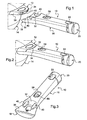
- FIG 1 shows a removable handle 10 designed to cooperate by interlocking with a base 12 integral with a kitchen utensil 14, such as for example a pan, a saucepan, etc.
- the kitchen utensil 14 itself can be made of different materials, for example stainless steel, resistant glass, ceramic, etc.
- the fastening of the base 12 on the utensil itself can be realized by different means, as will be seen later.
- the handle 10 is removable and is adapted to fit on the base by a simple fitting movement in a direction of translation which corresponds substantially to the longitudinal direction of the handle, which ensures the introduction and removal of the handle by a simple linear motion.
- the pressing movement and the reverse movement can thus be performed with one hand.
- the figure 2 shows the relative positions of the handle and the base in the position of fitting or locking.
- the handle 10 comprises a body 16 of oblong shape formed by the assembly of molded plastic parts.
- a body 16 of oblong shape formed by the assembly of molded plastic parts.
- plastics having suitable strength and heat resistance properties, including phenoplasts, such as Bakelite®, can be used for this purpose.
- This body 16 is provided with an extension 18 designed to bear under the base 12.
- This extension is located towards the front end of the handle, its rear end being provided with an end plug 20 which defines, jointly with the body 16, a through passage 22 to allow for example the attachment of the handle on a suitable support.
- the body 16 is formed by the assembly of two molded shells, namely an upper shell 24 and a lower shell 26 ( figure 5 ). These two shells are fixed together by a screw 28 passing through the upper shell 24 to engage the lower shell 26 in the region of the extension 18 and a screw 30 passing through the lower shell 26 to engage the upper shell 24 in a region near the plug 20. This plug is then reported for example by means of a screw at the end of the body of the handle.
- the body 16 of the handle has a front wall 32 of curved shape, intended to abut against a front wall 34 of the base 12 in the position of fitting of the handle ( figure 2 ).
- the front wall 32 is connected to an upper wall 36 of the extension 18 which is provided to bear under a lower wall 38 of the base.
- the walls 36 and 38 are here made substantially flat, but could have a different shape, for example raised on the sides.
- the handle 10 is provided with two guide rods 40 which extend parallel to each other and substantially in the longitudinal direction of the handle and are intended to engage in the base to provide a translational guide for the fitting of the handle. the handle on the base.
- These two guide rods 40 ( Figures 1 and 3 ) are housed in the upper shell 24 and fixed in the latter by any appropriate means. They pass through the front wall 32 and extend parallel to the upper wall 36 of the extension to form a fork.
- These guide rods are preferably made of metal, in particular stainless steel, and are provided for engaging respectively in two housings 42 ( figure 1 ) of the base.
- the handle 10 houses a movable magnet 44 carried by a cylinder 46 of generally circular cylindrical shape rotatably mounted about an axis of rotation XX which is inclined with respect to the longitudinal direction of the handle and in particular with respect to the plane defined by the upper wall 36 of the extension 18.
- the magnet 44 is disposed behind the front wall 32, made in the form of a thin wall, the north and south poles (N and S) of the magnet being arranged radially from on both sides of the axis of rotation. It follows that the effects of the magnet 44 can be exerted through the front wall 32. However, the movable magnet could, alternatively, be exposed directly to the outside as mentioned above.
- the front wall 32 and the upper wall 36 of the handle form an angle greater than 90 °, typically of the order of 120 °.
- the front wall 34 forms with the bottom wall 38 of the base a corresponding angle greater than 90 °, typically of the order of 120 °.
- the aforementioned angle could, alternatively, have a lower value, for example less than 90 °.
- the movable magnet 44 is provided to cooperate with a fixed magnet 48 housed inside the base 12 and whose respective north and south poles (N 'and S') are also arranged radially with respect to the aforementioned axis when the handle is engaged on the base as shown in figure 5 .
- the base 12 is fixed on a projection 50 of the utensil 14 by means of a screw 52 housed internally in the base.
- the magnet 48 is placed immediately behind the front wall 34 of the base which is also made with a small thickness so that the effects of this magnet can be exerted through the front wall 34.
- the fixed magnet 48 could alternatively be exposed directly to the outside, as indicated above.
- the movable magnet 44 can be rotated by a drive mechanism, which will be described later, from one to the other of two positions comprising a locking position and an unlocking position.
- the movable magnet Under the action of the drive mechanism, the movable magnet can be brought into an unlocking position in which the north and south poles (N and S) of the movable magnet 44 and the north and south poles (N 'and S ') of the fixed magnet 48 repel each other respectively.
- the transition from the lock position to the unlocking position is effected by a rotation in the direction of the arrow F 1 as shown in FIG. the figure 6 .
- the rotation interval between the two positions should be 180 ° to reach an unlocking position in which the north poles N and N 'are vis-à-vis and the south poles S and S' are screwed -a-vis.
- a rotation of at least 90 °, typically of the order of 120 ° is sufficient to allow repulsion in the unlocking position.
- the mechanism for rotating the barrel 46 and thus the magnet 44 comprises a rod 54 ( Figures 4 and 5 ) extending substantially in the longitudinal direction of the handle and rotatably coupled to the movable magnet.
- this rotational coupling is effected by means of a universal coupling 56, which allows the axis of rotation XX of the movable magnet to be inclined angularly with respect to the axis of rotation. YY rotation of the rod.
- the rod 54 To move the magnet 44 from one to the other of its two extreme positions, the rod 54 must be rotated over an angular interval which, in the example, is about 120 °.
- the drive mechanism is coupled to a slider or pusher 58 passing through a slot 60 having the shape of an oblong opening arranged in the upper part of the handle, in the shell 24.
- the slider 58 is resiliently biased to a first position (near the front end of the handle) corresponding to the locking position of the movable magnet.
- Slider 58 may be moved manually, i.e. towards the rear end of the handle, to a second position corresponding to the unlocking position of the movable magnet.
- the drive mechanism further comprises a rack 62 integral with the slider 58, which meshes with a spur gear 64 ( figure 4 ).
- This spur gear is wedged on an axis 66 which extends perpendicularly to the longitudinal axis of the handle and on which is locked a return pinion 68 which meshes with another pinion gear 70 integral in rotation with the drive rod. .
- the slider 58 is further biased by a helical spring 72 to its first position or rest position.
- the handle also houses a locking hook 74 ( Figures 4 and 5 ) capable of being actuated at least in part by the rotation of the movable magnet and adapted to be placed in one or other of two positions comprising a locking position in which the hook is provided to engage in the base and an unlocking position in which the hook is provided to disengage the base.
- a locking hook 74 Figures 4 and 5
- the locking hook is made in the form of a tilting element about an axis 76 ( Figures 4 and 5 ).
- the locking hook 74 is housed in the extension 18 of the handle and is subjected to the action of a spring 78 tending to move it to the locking position in which it protrudes from the handle.
- the hook 74 has an inclined face 80 which protrudes from the plane of the upper wall 36 of the extension in the locking position so as to engage in a recess 82 opening into the bottom wall 38 of the base. In the locking position, the hook engages in the notch and thus ensures the immobilization of the handle on the base.
- the locking hook 74 can also be moved to the unlocking position in which it is at least partly retracted into the handle.
- the transition from the locking position to the unlocking position is performed automatically by tilting the hook about its axis 76 when the handle is fitted on the base.
- the barrel 46 ( Figures 7 and 8 ) has a circular cylindrical contour and further forms a peripheral cam 84 adapted to cooperate with a stop 86 of the locking hook to move it from one to the other of its locking position and its unlocking position. Under the action of the spring 78, the stop 84 bears on the cam 86.
- the latter has a progressive shape and extends over approximately 120 ° between a half axis OA and a half axis OB. At point A (high point), cam 84 is at a distance d from the periphery of the barrel, while at point B (low point), it reaches the periphery of the barrel. The distance d thus defines a displacement travel of the stop 84 between two extreme positions.
- the stop 84 In the position of the figure 7 the stop 84 is in the deepest part of the cam 86 (low point B). As the barrel 46 is rotated in the direction of the arrow F 1 (here clockwise), the stop 84 moves in translation in the direction of the arrow F 2 away from the center of the barrel O to reach the position of the figure 8 (high point A).
- the stop 84 has moved by the distance d, which makes it possible to tilt and unlock the locking hook 74, compressing the spring 78 ( figure 5 ).
- the handle of the invention is used as follows. To achieve its fitting on the base, simply engage it by a simple translational movement by cooperating the respective faces of the handle and the base and also engaging the rods 40 in the housing 42 of the base . During engagement, the magnets 44 and 48 attract and at the same time the unlocking hook rocker to provide a mechanical lock in the base. To ensure the removal of the handle, simply act on the slider 58, which ensures both the rotation of the movable magnet 44 so that the two magnets are pushing and tilting the locking hook 74 from the locking position to the unlocking position.
- the drive rod 54 could be coupled directly to a rotary knob placed at the end of the handle.
- this rod could be coupled directly to the barrel carrying the movable magnet 44.
- the magnets 44 and 48 advantageously have a generally parallelepipedal shape, for example a cubic shape, so as to provide two flat faces facing each other.
- Other forms are possible as long as the two poles of the movable magnet are mutually spaced in a direction transverse to the axis of rotation of the movable magnet. It is the same for the fixed magnet whose two poles must be mutually spaced in a direction transverse to the axis of fitting of the handle.
- the invention applies to different types of kitchen utensils, such as pots, pans, dishes, etc.
Landscapes
- Engineering & Computer Science (AREA)
- Food Science & Technology (AREA)
- Food-Manufacturing Devices (AREA)
- Table Equipment (AREA)
Claims (17)
- Abnehmbarer Griff für ein Küchengerät, der in der Lage ist, mit einem Unterteil des Geräts zusammenzuwirken, dadurch gekennzeichnet, dass der Griff (10) einen beweglichen Magneten (44) aufnimmt, der in der Lage ist, in Drehung um eine Drehachse (XX) angetrieben zu werden, die sich im Wesentlichen in der Längsrichtung des Griffs erstreckt, wobei die Pole (N, S) des beweglichen Magneten (44) radial beiderseits der Drehachse (XX) angeordnet sind, wobei der bewegliche Magnet (44) vorgesehen ist, um mit einem festen Magneten (48), der von dem Unterteil (12) getragen wird, zusammenzuwirken, und einen Antriebsmechanismus (54, 56) aufnimmt, der in der Lage ist, den beweglichen Magneten (44) von der einen in die andere der beiden Positionen anzutreiben, umfassend eine Verriegelungsposition, in der die Pole (N, S) des beweglichen Magneten (44) und die Pole (N', S') des festen Magneten (48) sich anziehen und eine Entriegelungsposition, in der die Pole (N, S) des beweglichen Magneten (44) und die Pole (N', S') des festen Magneten (48) sich voneinander abstoßen, sowie einen Verriegelungshaken (74) aufnimmt, der wenigstens teilweise durch die Drehung des beweglichen Magneten (44) betätigt wird und in der Lage ist, in die eine oder die andere der beiden Positionen gesetzt zu werden, umfassend eine Verriegelungsposition, in der der Verriegelungshaken vorgesehen ist, in das Unterteil einzugreifen und eine Entriegelungsposition, in der der Verriegelungshaken vorgesehen ist, das Unterteil freizugeben.
- Abnehmbarer Griff nach Anspruch 1, mit einem Körper (16) von länglicher Form, der den beweglichen Magneten (44) und den Antriebsmechanismus (54, 56) sowie eine Verlängerung (18) aufnimmt, die vorgesehen ist, um sich auf dem Unterteil abzustützen und den Verriegelungshaken (74) aufzunehmen.
- Abnehmbarer Griff nach Anspruch 2, bei dem der bewegliche Magnet (44) hinter einer Vorderwand (32) des Griffs angeordnet ist, die vorgesehen ist, um in Anschlag gegen eine Vorderwand (34) des Unterteils zu kommen und sich mit einer oberen Wand (36) der Verlängerung (18) verbindet, die vorgesehen ist, um unter eine untere Wand (38) des Unterteils zu drücken, und in der ein Hohlraum mündet, der den Verriegelungshaken (74) aufnimmt.
- Abnehmbarer Griff nach einem der Ansprüche 1 bis 3, bei dem der bewegliche Magnet (44) durch eine Trommel (46) von allgemeiner Zylinderform getragen wird, drehbeweglich angebracht in dem Griff und gekoppelt mit dem Antriebsmechanismus (54, 56), wobei die Trommel einen Umfangsnocken (48) bildet, der geeignet ist, mit einem Anschlag (46) des Verriegelungshakens (74) zusammenzuwirken, um ihn von der einen in die andere seiner Verriegelungsposition und seiner Entriegelungsposition zu bewegen.
- Entfernbarer Griff nach einem der Ansprüche 1 bis 4, bei dem der bewegliche Magnet (44) geeignet ist, über einen Winkelabstand von wenigstens 90° zu drehen, um sich von der einen zur anderen seiner Verriegelungs- und Entriegelungspositionen zu bewegen.
- Abnehmbarer Griff nach einem der Ansprüche 1 bis 5, bei der der Verriegelungshaken (74) der Einwirkung einer Feder (78) unterworfen ist, die dazu drängt, den Verriegelungshaken in die Verriegelungsposition zu bewegen, in der er von dem Griff vorspringt und vorgesehen ist, in das Unterteil einzugreifen, wobei der Verriegelungshaken in der Lage ist, in die Entriegelungsposition verschoben zu werden, in der er wenigstens teilweise in dem Griff eingefahren ist.
- Abnehmbarer Griff nach einem der Ansprüche 1 bis 6, bei dem der Verriegelungshaken (74) eine geneigte Fläche (80) aufweist, die vorgesehen ist, um mit dem Unterteil beim Vorortsetzen des Griffs an das Unterteil zusammenzuwirken, um den Verriegelungshaken in Entriegelungsposition sodann in Verriegelungsposition zu bringen.
- Abnehmbarer Griff nach einem der Ansprüche 1 bis 7, bei dem der Antriebsmechanismus eine Antriebsstange (54) aufweist, die sich im Wesentlichen in der Längsrichtung des Griffs erstreckt, und beim Drehen mit dem beweglichen Magneten (44) gekoppelt ist.
- Abnehmbarer Griff nach Anspruch 8, bei dem die Antriebsstange (54) in Drehung mit dem beweglichen Magneten (44) mittels einer Universalkupplung (56) gekoppelt ist, derart, dass die Drehachse (XX) des beweglichen Magneten (44) winkelmäßig bezüglich der Drehachse der Antriebsstange geneigt ist.
- Abnehmbarer Griff nach einem der Ansprüche 1 bis 9, bei dem der Antriebsmechanismus (54, 56) mit einem Schieber (58) gekoppelt ist, der in eine erste Position, entsprechend der Verriegelungsposition des beweglichen Magneten zurückgesetzt ist, und in der Lage ist, manuell in eine zweite Position verschoben zu werden, die der Entriegelungsposition des beweglichen Magneten entspricht.
- Abnehmbarer Griff nach Anspruch 10 in Kombination mit Anspruch 8, bei dem der Antriebsmechanismus eine mit dem Schieber (58) verbundene Zahnstange (62) aufweist, die in Eingriff steht mit einem geraden Ritzel (64), das drehverbunden ist mit einem Rücksetzritzel (68), das in Eingriff steht mit einem Rücksetzritzel (70), das drehverbunden ist mit der Antriebsstange (54).
- Abnehmbarer Griff nach einem der Ansprüche 1 bis 11, bei dem der Griff mit wenigstens einer Führungsstange (40) versehen ist, die sich im Wesentlichen in die Längsrichtung des Griffs erstreckt und vorgesehen ist, um in Eingriff zu kommen mit dem Unterteil (12), um eine Translationsführung für das Einsetzen des Griffs in das Unterteil sicherzustellen.
- Küchengerät mit einem Unterteil (12), das vorgesehen ist, um einen abnehmbaren Griff aufzunehmen, dadurch gekennzeichnet, dass das Unterteil einen festen Magneten (48) aufnimmt, dessen entsprechende Pole (N', S') beiderseits einer Achse angeordnet sind, die eine Einsetzachse des Griffs definiert und dass das Unterteil eine Ausnehmung (82) aufweist, die vorgesehen ist, um einen Verriegelungshaken des Griffs aufzunehmen.
- Küchengerät nach Anspruch 13, bei dem das Unterteil (12) eine Vorderwand (34) aufweist, die vorgesehen ist, um in Anschlag gegen eine Vorderwand des Griffs zu kommen, und sich mit einer unteren Wand (38) verbindet, um in Anlage an eine obere Wand des Unterteils zu kommen.
- Küchengerät nach Anspruch 14, bei dem der feste Magnet (48) hinter der Vorderwand (34) des Unterteils angeordnet ist und die Ausnehmung (82) in der unteren Wand (38) des Unterteils (12) mündet.
- Küchengerät nach einem der Ansprüche 13 bis 15, bei dem das Unterteil wenigstens eine Aufnahme (42) aufweist, die vorgesehen ist, um eine Führungsstange (40) des Griffs aufzunehmen, um eine Translationsführung für das Einsetzen des Griffs in das Unterteil sicherzustellen.
- Greifvorrichtung mit einem abnehmbaren Griff nach einem der Ansprüche 1 bis 12 und einem Küchengerät nach einem der Ansprüche 13 bis 16.
Applications Claiming Priority (1)
| Application Number | Priority Date | Filing Date | Title |
|---|---|---|---|
| FR1103787A FR2983693B1 (fr) | 2011-12-09 | 2011-12-09 | Poignee amovible et ustensile de cuisine adapte a cette poignee |
Publications (2)
| Publication Number | Publication Date |
|---|---|
| EP2601871A1 EP2601871A1 (de) | 2013-06-12 |
| EP2601871B1 true EP2601871B1 (de) | 2014-04-23 |
Family
ID=47294817
Family Applications (1)
| Application Number | Title | Priority Date | Filing Date |
|---|---|---|---|
| EP20120290425 Not-in-force EP2601871B1 (de) | 2011-12-09 | 2012-12-03 | Abnehmbarer Griff und Kochutensil für einen solchen Griff |
Country Status (3)
| Country | Link |
|---|---|
| EP (1) | EP2601871B1 (de) |
| ES (1) | ES2483166T3 (de) |
| FR (1) | FR2983693B1 (de) |
Cited By (2)
| Publication number | Priority date | Publication date | Assignee | Title |
|---|---|---|---|---|
| EP4221551A4 (de) * | 2020-09-29 | 2024-09-25 | Meyer Intellectual Properties Limited | Kochgeschirr mit abnehmbarem griff |
| US12274398B2 (en) | 2020-09-29 | 2025-04-15 | Meyer Intellectual Properties Limited | Cookware vessel with removable handle |
Families Citing this family (9)
| Publication number | Priority date | Publication date | Assignee | Title |
|---|---|---|---|---|
| CN104274081A (zh) * | 2013-07-12 | 2015-01-14 | 宁波卡特马克炊具科技有限公司 | 一种锅子及其制备方法 |
| KR101509482B1 (ko) * | 2014-05-29 | 2015-04-08 | 이동우 | 주방용기용 접이식 손잡이 구조 |
| CN107049081B (zh) * | 2015-03-16 | 2020-04-03 | 浙江诺维雅工贸有限公司 | 一种可拆卸手柄 |
| CN104873122B (zh) * | 2015-05-21 | 2017-05-24 | 常熟卡斯玛因厨具有限公司 | 磁铁旋转可脱卸式锅提手及其锅体连接装置 |
| IT201700010532A1 (it) * | 2017-01-31 | 2018-07-31 | Bib Srl | Contenitore per la cottura di prodotti alimentari |
| CN108758579A (zh) * | 2018-06-15 | 2018-11-06 | 柏赛塑胶科技(珠海保税区)有限公司 | 一种可灵活布设的电路装置 |
| CN109077765A (zh) * | 2018-09-12 | 2018-12-25 | 苏州法兰克曼医疗器械有限公司 | 一种具有新型锁定控制机构的外科器械 |
| CN115429135B (zh) * | 2021-06-02 | 2024-11-15 | 浙江三禾厨具有限公司 | 可拆锅用手柄 |
| CN116919215B (zh) * | 2022-04-02 | 2025-10-31 | 浙江天喜厨电股份有限公司 | 一种用于空气炸锅的可拆卸握柄装置及其空气炸锅 |
Family Cites Families (8)
| Publication number | Priority date | Publication date | Assignee | Title |
|---|---|---|---|---|
| FR2220767B1 (de) | 1973-03-08 | 1976-11-05 | France Etat | |
| FR2758074B1 (fr) | 1997-01-08 | 1999-03-26 | Dja Cristel | Dispositif de prehension pour ustensile de cuisson |
| ES2245533B1 (es) | 2002-11-04 | 2007-05-01 | Armando Moli Campderrich | Utensilio de cocina y utilizaciones correspondientes. |
| US20050015933A1 (en) * | 2003-07-25 | 2005-01-27 | Tom Hasegawa | Removable handles for cooking vessels and cooking vessels using same |
| FR2893494B1 (fr) * | 2005-11-23 | 2013-04-05 | Seb Sa | Organe de prehension de couvercle aimante |
| FR2898032B1 (fr) | 2006-03-06 | 2008-04-18 | Seb Sa | Dispositif de prehension amovible avec moyens d'ouverture des organes formant pince |
| NO328146B1 (no) * | 2008-04-03 | 2009-12-21 | Mnt As | Magnetisk frigjorbart handtak for et lokk eller lignende |
| RO126365A2 (ro) * | 2009-12-03 | 2011-06-30 | Adrian Leonard Militaru | Capac multifuncţional cu mâner magnetic, detaşabil, pentru vase de gătit |
-
2011
- 2011-12-09 FR FR1103787A patent/FR2983693B1/fr not_active Expired - Fee Related
-
2012
- 2012-12-03 ES ES12290425.3T patent/ES2483166T3/es active Active
- 2012-12-03 EP EP20120290425 patent/EP2601871B1/de not_active Not-in-force
Cited By (2)
| Publication number | Priority date | Publication date | Assignee | Title |
|---|---|---|---|---|
| EP4221551A4 (de) * | 2020-09-29 | 2024-09-25 | Meyer Intellectual Properties Limited | Kochgeschirr mit abnehmbarem griff |
| US12274398B2 (en) | 2020-09-29 | 2025-04-15 | Meyer Intellectual Properties Limited | Cookware vessel with removable handle |
Also Published As
| Publication number | Publication date |
|---|---|
| ES2483166T3 (es) | 2014-08-05 |
| FR2983693A1 (fr) | 2013-06-14 |
| EP2601871A1 (de) | 2013-06-12 |
| FR2983693B1 (fr) | 2015-03-06 |
Similar Documents
| Publication | Publication Date | Title |
|---|---|---|
| EP2601871B1 (de) | Abnehmbarer Griff und Kochutensil für einen solchen Griff | |
| FR3059534B1 (fr) | Autocuiseur a baionnette et verrou mobile | |
| EP2204112B1 (de) | Dampfdruckkochtopf mit Steuerorgan zum Verriegeln und Entriegeln mit asymetrischem Verhalten | |
| EP2687132B1 (de) | Druckkochgerät mit verbesserter Bedienungsvorrichtung | |
| EP1991097B1 (de) | Halterung für ein küchenutensil | |
| CA1283788C (fr) | Serrure a armement par commande electrique | |
| EP3888511B1 (de) | Abnehmbarer griff mit mobiler verriegelung | |
| EP3345520B1 (de) | Abnehmbarer griff, der mit einem öffnungssystem mit einem schwenkbaren knopf ausgestattet ist | |
| WO2001043611A1 (fr) | Dispositif de prehension pour ustensile de cuisson | |
| FR3038505A1 (fr) | Poignee amovible | |
| WO2021205039A1 (fr) | Volant de vehicule avec structure mobile et dispositif de blocage | |
| FR3059533A1 (fr) | Autocuiseur a baionnette a poignees de cuve et de couvercle interverrouillables | |
| EP3319498B1 (de) | Abnehmbarer griff mit einem öffnungssystem mit zwei wippknöpfen | |
| EP3253615A1 (de) | Lösbare scharnieranordnung für einen kraftfahrzeugsitz | |
| FR3117985A1 (fr) | Volant de vehicule automobile a jante repliable ou escamotable | |
| EP1745728B1 (de) | Küchengerät mit rotierendem Werkzeug und spezieller Sicherheitsvorrichtung | |
| EP2438841B1 (de) | Elektrogerät zur Zubereitung von Speisen, das mit einem Zubehör zur Aufhängung von Küchenwerkzeugen ausgestattet ist | |
| EP1793712B1 (de) | Vorrichtung mit einem behälter für flaschen | |
| FR2809438A1 (fr) | Serrure, pour portiere de vehicule, comportant une fonction securite enfant et une fonction supercondamnation | |
| EP0852924B1 (de) | Griffelement für Kochgeschirr | |
| FR2822364A1 (fr) | Appareil electromenager de preparation culinaire comportant un outil rotatif et un double dispositif de securite | |
| FR2852794A1 (fr) | Boitier comportant un systeme de fermeture magnetique | |
| FR2798950A1 (fr) | Dispositif de verrouillage comportant un doigt de transmission debrayable commande par came | |
| EP1669527B1 (de) | Treibstangenverschluss für Koffer | |
| FR2973207A1 (fr) | Chaise de table pour enfant securisee |
Legal Events
| Date | Code | Title | Description |
|---|---|---|---|
| PUAI | Public reference made under article 153(3) epc to a published international application that has entered the european phase |
Free format text: ORIGINAL CODE: 0009012 |
|
| AK | Designated contracting states |
Kind code of ref document: A1 Designated state(s): AL AT BE BG CH CY CZ DE DK EE ES FI FR GB GR HR HU IE IS IT LI LT LU LV MC MK MT NL NO PL PT RO RS SE SI SK SM TR |
|
| AX | Request for extension of the european patent |
Extension state: BA ME |
|
| 17P | Request for examination filed |
Effective date: 20130704 |
|
| GRAP | Despatch of communication of intention to grant a patent |
Free format text: ORIGINAL CODE: EPIDOSNIGR1 |
|
| GRAC | Information related to communication of intention to grant a patent modified |
Free format text: ORIGINAL CODE: EPIDOSCIGR1 |
|
| GRAJ | Information related to disapproval of communication of intention to grant by the applicant or resumption of examination proceedings by the epo deleted |
Free format text: ORIGINAL CODE: EPIDOSDIGR1 |
|
| GRAP | Despatch of communication of intention to grant a patent |
Free format text: ORIGINAL CODE: EPIDOSNIGR1 |
|
| INTG | Intention to grant announced |
Effective date: 20131106 |
|
| INTG | Intention to grant announced |
Effective date: 20131106 |
|
| RAP1 | Party data changed (applicant data changed or rights of an application transferred) |
Owner name: ARC INTERNATIONAL COOKWARE SAS |
|
| GRAS | Grant fee paid |
Free format text: ORIGINAL CODE: EPIDOSNIGR3 |
|
| GRAA | (expected) grant |
Free format text: ORIGINAL CODE: 0009210 |
|
| AK | Designated contracting states |
Kind code of ref document: B1 Designated state(s): AL AT BE BG CH CY CZ DE DK EE ES FI FR GB GR HR HU IE IS IT LI LT LU LV MC MK MT NL NO PL PT RO RS SE SI SK SM TR |
|
| REG | Reference to a national code |
Ref country code: GB Ref legal event code: FG4D Free format text: NOT ENGLISH |
|
| REG | Reference to a national code |
Ref country code: CH Ref legal event code: EP |
|
| REG | Reference to a national code |
Ref country code: AT Ref legal event code: REF Ref document number: 663259 Country of ref document: AT Kind code of ref document: T Effective date: 20140515 |
|
| REG | Reference to a national code |
Ref country code: IE Ref legal event code: FG4D Free format text: LANGUAGE OF EP DOCUMENT: FRENCH |
|
| REG | Reference to a national code |
Ref country code: DE Ref legal event code: R096 Ref document number: 602012001496 Country of ref document: DE Effective date: 20140528 |
|
| REG | Reference to a national code |
Ref country code: ES Ref legal event code: FG2A Ref document number: 2483166 Country of ref document: ES Kind code of ref document: T3 Effective date: 20140805 |
|
| RAP2 | Party data changed (patent owner data changed or rights of a patent transferred) |
Owner name: INTERNATIONAL COOKWARE |
|
| REG | Reference to a national code |
Ref country code: CH Ref legal event code: NV Representative=s name: KATZAROV S.A., CH Ref country code: CH Ref legal event code: PFA Owner name: INTERNATIONAL COOKWARE, FR Free format text: FORMER OWNER: ARC INTERNATIONAL COOKWARE SAS, FR |
|
| REG | Reference to a national code |
Ref country code: AT Ref legal event code: MK05 Ref document number: 663259 Country of ref document: AT Kind code of ref document: T Effective date: 20140423 |
|
| REG | Reference to a national code |
Ref country code: NL Ref legal event code: VDEP Effective date: 20140423 |
|
| REG | Reference to a national code |
Ref country code: LT Ref legal event code: MG4D |
|
| PG25 | Lapsed in a contracting state [announced via postgrant information from national office to epo] |
Ref country code: IS Free format text: LAPSE BECAUSE OF FAILURE TO SUBMIT A TRANSLATION OF THE DESCRIPTION OR TO PAY THE FEE WITHIN THE PRESCRIBED TIME-LIMIT Effective date: 20140823 Ref country code: CY Free format text: LAPSE BECAUSE OF FAILURE TO SUBMIT A TRANSLATION OF THE DESCRIPTION OR TO PAY THE FEE WITHIN THE PRESCRIBED TIME-LIMIT Effective date: 20140423 Ref country code: GR Free format text: LAPSE BECAUSE OF FAILURE TO SUBMIT A TRANSLATION OF THE DESCRIPTION OR TO PAY THE FEE WITHIN THE PRESCRIBED TIME-LIMIT Effective date: 20140724 Ref country code: LT Free format text: LAPSE BECAUSE OF FAILURE TO SUBMIT A TRANSLATION OF THE DESCRIPTION OR TO PAY THE FEE WITHIN THE PRESCRIBED TIME-LIMIT Effective date: 20140423 Ref country code: NL Free format text: LAPSE BECAUSE OF FAILURE TO SUBMIT A TRANSLATION OF THE DESCRIPTION OR TO PAY THE FEE WITHIN THE PRESCRIBED TIME-LIMIT Effective date: 20140423 Ref country code: NO Free format text: LAPSE BECAUSE OF FAILURE TO SUBMIT A TRANSLATION OF THE DESCRIPTION OR TO PAY THE FEE WITHIN THE PRESCRIBED TIME-LIMIT Effective date: 20140723 Ref country code: BG Free format text: LAPSE BECAUSE OF FAILURE TO SUBMIT A TRANSLATION OF THE DESCRIPTION OR TO PAY THE FEE WITHIN THE PRESCRIBED TIME-LIMIT Effective date: 20140723 |
|
| PG25 | Lapsed in a contracting state [announced via postgrant information from national office to epo] |
Ref country code: PL Free format text: LAPSE BECAUSE OF FAILURE TO SUBMIT A TRANSLATION OF THE DESCRIPTION OR TO PAY THE FEE WITHIN THE PRESCRIBED TIME-LIMIT Effective date: 20140423 Ref country code: AT Free format text: LAPSE BECAUSE OF FAILURE TO SUBMIT A TRANSLATION OF THE DESCRIPTION OR TO PAY THE FEE WITHIN THE PRESCRIBED TIME-LIMIT Effective date: 20140423 Ref country code: LV Free format text: LAPSE BECAUSE OF FAILURE TO SUBMIT A TRANSLATION OF THE DESCRIPTION OR TO PAY THE FEE WITHIN THE PRESCRIBED TIME-LIMIT Effective date: 20140423 Ref country code: HR Free format text: LAPSE BECAUSE OF FAILURE TO SUBMIT A TRANSLATION OF THE DESCRIPTION OR TO PAY THE FEE WITHIN THE PRESCRIBED TIME-LIMIT Effective date: 20140423 Ref country code: SE Free format text: LAPSE BECAUSE OF FAILURE TO SUBMIT A TRANSLATION OF THE DESCRIPTION OR TO PAY THE FEE WITHIN THE PRESCRIBED TIME-LIMIT Effective date: 20140423 Ref country code: RS Free format text: LAPSE BECAUSE OF FAILURE TO SUBMIT A TRANSLATION OF THE DESCRIPTION OR TO PAY THE FEE WITHIN THE PRESCRIBED TIME-LIMIT Effective date: 20140423 |
|
| PG25 | Lapsed in a contracting state [announced via postgrant information from national office to epo] |
Ref country code: PT Free format text: LAPSE BECAUSE OF FAILURE TO SUBMIT A TRANSLATION OF THE DESCRIPTION OR TO PAY THE FEE WITHIN THE PRESCRIBED TIME-LIMIT Effective date: 20140825 |
|
| REG | Reference to a national code |
Ref country code: DE Ref legal event code: R097 Ref document number: 602012001496 Country of ref document: DE |
|
| PG25 | Lapsed in a contracting state [announced via postgrant information from national office to epo] |
Ref country code: CZ Free format text: LAPSE BECAUSE OF FAILURE TO SUBMIT A TRANSLATION OF THE DESCRIPTION OR TO PAY THE FEE WITHIN THE PRESCRIBED TIME-LIMIT Effective date: 20140423 Ref country code: DK Free format text: LAPSE BECAUSE OF FAILURE TO SUBMIT A TRANSLATION OF THE DESCRIPTION OR TO PAY THE FEE WITHIN THE PRESCRIBED TIME-LIMIT Effective date: 20140423 Ref country code: EE Free format text: LAPSE BECAUSE OF FAILURE TO SUBMIT A TRANSLATION OF THE DESCRIPTION OR TO PAY THE FEE WITHIN THE PRESCRIBED TIME-LIMIT Effective date: 20140423 Ref country code: SK Free format text: LAPSE BECAUSE OF FAILURE TO SUBMIT A TRANSLATION OF THE DESCRIPTION OR TO PAY THE FEE WITHIN THE PRESCRIBED TIME-LIMIT Effective date: 20140423 Ref country code: RO Free format text: LAPSE BECAUSE OF FAILURE TO SUBMIT A TRANSLATION OF THE DESCRIPTION OR TO PAY THE FEE WITHIN THE PRESCRIBED TIME-LIMIT Effective date: 20140423 |
|
| PLBE | No opposition filed within time limit |
Free format text: ORIGINAL CODE: 0009261 |
|
| STAA | Information on the status of an ep patent application or granted ep patent |
Free format text: STATUS: NO OPPOSITION FILED WITHIN TIME LIMIT |
|
| 26N | No opposition filed |
Effective date: 20150126 |
|
| REG | Reference to a national code |
Ref country code: DE Ref legal event code: R097 Ref document number: 602012001496 Country of ref document: DE Effective date: 20150126 |
|
| PG25 | Lapsed in a contracting state [announced via postgrant information from national office to epo] |
Ref country code: SI Free format text: LAPSE BECAUSE OF FAILURE TO SUBMIT A TRANSLATION OF THE DESCRIPTION OR TO PAY THE FEE WITHIN THE PRESCRIBED TIME-LIMIT Effective date: 20140423 Ref country code: LU Free format text: LAPSE BECAUSE OF FAILURE TO SUBMIT A TRANSLATION OF THE DESCRIPTION OR TO PAY THE FEE WITHIN THE PRESCRIBED TIME-LIMIT Effective date: 20141203 |
|
| REG | Reference to a national code |
Ref country code: IE Ref legal event code: MM4A |
|
| PG25 | Lapsed in a contracting state [announced via postgrant information from national office to epo] |
Ref country code: IE Free format text: LAPSE BECAUSE OF NON-PAYMENT OF DUE FEES Effective date: 20141203 |
|
| REG | Reference to a national code |
Ref country code: FR Ref legal event code: PLFP Year of fee payment: 4 |
|
| PG25 | Lapsed in a contracting state [announced via postgrant information from national office to epo] |
Ref country code: MC Free format text: LAPSE BECAUSE OF FAILURE TO SUBMIT A TRANSLATION OF THE DESCRIPTION OR TO PAY THE FEE WITHIN THE PRESCRIBED TIME-LIMIT Effective date: 20140423 |
|
| PG25 | Lapsed in a contracting state [announced via postgrant information from national office to epo] |
Ref country code: HU Free format text: LAPSE BECAUSE OF FAILURE TO SUBMIT A TRANSLATION OF THE DESCRIPTION OR TO PAY THE FEE WITHIN THE PRESCRIBED TIME-LIMIT; INVALID AB INITIO Effective date: 20121203 Ref country code: TR Free format text: LAPSE BECAUSE OF FAILURE TO SUBMIT A TRANSLATION OF THE DESCRIPTION OR TO PAY THE FEE WITHIN THE PRESCRIBED TIME-LIMIT Effective date: 20140423 Ref country code: MT Free format text: LAPSE BECAUSE OF FAILURE TO SUBMIT A TRANSLATION OF THE DESCRIPTION OR TO PAY THE FEE WITHIN THE PRESCRIBED TIME-LIMIT Effective date: 20140423 |
|
| REG | Reference to a national code |
Ref country code: FR Ref legal event code: PLFP Year of fee payment: 5 |
|
| PG25 | Lapsed in a contracting state [announced via postgrant information from national office to epo] |
Ref country code: SM Free format text: LAPSE BECAUSE OF FAILURE TO SUBMIT A TRANSLATION OF THE DESCRIPTION OR TO PAY THE FEE WITHIN THE PRESCRIBED TIME-LIMIT Effective date: 20140423 |
|
| REG | Reference to a national code |
Ref country code: FR Ref legal event code: PLFP Year of fee payment: 6 |
|
| REG | Reference to a national code |
Ref country code: CH Ref legal event code: PCAR Free format text: NEW ADDRESS: AVENUE DES MORGINES 12, 1213 PETIT-LANCY (CH) |
|
| PG25 | Lapsed in a contracting state [announced via postgrant information from national office to epo] |
Ref country code: MK Free format text: LAPSE BECAUSE OF FAILURE TO SUBMIT A TRANSLATION OF THE DESCRIPTION OR TO PAY THE FEE WITHIN THE PRESCRIBED TIME-LIMIT Effective date: 20140423 |
|
| PG25 | Lapsed in a contracting state [announced via postgrant information from national office to epo] |
Ref country code: AL Free format text: LAPSE BECAUSE OF FAILURE TO SUBMIT A TRANSLATION OF THE DESCRIPTION OR TO PAY THE FEE WITHIN THE PRESCRIBED TIME-LIMIT Effective date: 20140423 |
|
| PGFP | Annual fee paid to national office [announced via postgrant information from national office to epo] |
Ref country code: FI Payment date: 20201222 Year of fee payment: 9 Ref country code: DE Payment date: 20201211 Year of fee payment: 9 Ref country code: FR Payment date: 20201217 Year of fee payment: 9 Ref country code: GB Payment date: 20201223 Year of fee payment: 9 Ref country code: CH Payment date: 20201221 Year of fee payment: 9 |
|
| PGFP | Annual fee paid to national office [announced via postgrant information from national office to epo] |
Ref country code: IT Payment date: 20201224 Year of fee payment: 9 |
|
| PGFP | Annual fee paid to national office [announced via postgrant information from national office to epo] |
Ref country code: ES Payment date: 20210223 Year of fee payment: 9 Ref country code: BE Payment date: 20201231 Year of fee payment: 9 |
|
| REG | Reference to a national code |
Ref country code: DE Ref legal event code: R119 Ref document number: 602012001496 Country of ref document: DE |
|
| REG | Reference to a national code |
Ref country code: FI Ref legal event code: MAE |
|
| REG | Reference to a national code |
Ref country code: CH Ref legal event code: PL |
|
| GBPC | Gb: european patent ceased through non-payment of renewal fee |
Effective date: 20211203 |
|
| PG25 | Lapsed in a contracting state [announced via postgrant information from national office to epo] |
Ref country code: FI Free format text: LAPSE BECAUSE OF NON-PAYMENT OF DUE FEES Effective date: 20211203 |
|
| REG | Reference to a national code |
Ref country code: BE Ref legal event code: MM Effective date: 20211231 |
|
| PG25 | Lapsed in a contracting state [announced via postgrant information from national office to epo] |
Ref country code: GB Free format text: LAPSE BECAUSE OF NON-PAYMENT OF DUE FEES Effective date: 20211203 Ref country code: DE Free format text: LAPSE BECAUSE OF NON-PAYMENT OF DUE FEES Effective date: 20220701 |
|
| PG25 | Lapsed in a contracting state [announced via postgrant information from national office to epo] |
Ref country code: FR Free format text: LAPSE BECAUSE OF NON-PAYMENT OF DUE FEES Effective date: 20211231 Ref country code: BE Free format text: LAPSE BECAUSE OF NON-PAYMENT OF DUE FEES Effective date: 20211231 |
|
| PG25 | Lapsed in a contracting state [announced via postgrant information from national office to epo] |
Ref country code: LI Free format text: LAPSE BECAUSE OF NON-PAYMENT OF DUE FEES Effective date: 20211231 Ref country code: CH Free format text: LAPSE BECAUSE OF NON-PAYMENT OF DUE FEES Effective date: 20211231 |
|
| PG25 | Lapsed in a contracting state [announced via postgrant information from national office to epo] |
Ref country code: IT Free format text: LAPSE BECAUSE OF NON-PAYMENT OF DUE FEES Effective date: 20211203 |
|
| REG | Reference to a national code |
Ref country code: ES Ref legal event code: FD2A Effective date: 20230301 |
|
| PG25 | Lapsed in a contracting state [announced via postgrant information from national office to epo] |
Ref country code: ES Free format text: LAPSE BECAUSE OF NON-PAYMENT OF DUE FEES Effective date: 20211204 |