EP2601895A1 - Instrument médical - Google Patents
Instrument médical Download PDFInfo
- Publication number
- EP2601895A1 EP2601895A1 EP12193321.2A EP12193321A EP2601895A1 EP 2601895 A1 EP2601895 A1 EP 2601895A1 EP 12193321 A EP12193321 A EP 12193321A EP 2601895 A1 EP2601895 A1 EP 2601895A1
- Authority
- EP
- European Patent Office
- Prior art keywords
- medical instrument
- rolling surfaces
- lever arms
- instrument according
- actuating element
- Prior art date
- Legal status (The legal status is an assumption and is not a legal conclusion. Google has not performed a legal analysis and makes no representation as to the accuracy of the status listed.)
- Granted
Links
Images



Classifications
-
- A—HUMAN NECESSITIES
- A61—MEDICAL OR VETERINARY SCIENCE; HYGIENE
- A61B—DIAGNOSIS; SURGERY; IDENTIFICATION
- A61B1/00—Instruments for performing medical examinations of the interior of cavities or tubes of the body by visual or photographical inspection, e.g. endoscopes; Illuminating arrangements therefor
- A61B1/012—Instruments for performing medical examinations of the interior of cavities or tubes of the body by visual or photographical inspection, e.g. endoscopes; Illuminating arrangements therefor characterised by internal passages or accessories therefor
- A61B1/018—Instruments for performing medical examinations of the interior of cavities or tubes of the body by visual or photographical inspection, e.g. endoscopes; Illuminating arrangements therefor characterised by internal passages or accessories therefor for receiving instruments
-
- A—HUMAN NECESSITIES
- A61—MEDICAL OR VETERINARY SCIENCE; HYGIENE
- A61B—DIAGNOSIS; SURGERY; IDENTIFICATION
- A61B17/00—Surgical instruments, devices or methods
- A61B17/28—Surgical forceps
- A61B17/29—Forceps for use in minimally invasive surgery
- A61B17/2909—Handles
-
- A—HUMAN NECESSITIES
- A61—MEDICAL OR VETERINARY SCIENCE; HYGIENE
- A61B—DIAGNOSIS; SURGERY; IDENTIFICATION
- A61B17/00—Surgical instruments, devices or methods
- A61B2017/0046—Surgical instruments, devices or methods with a releasable handle; with handle and operating part separable
-
- A—HUMAN NECESSITIES
- A61—MEDICAL OR VETERINARY SCIENCE; HYGIENE
- A61B—DIAGNOSIS; SURGERY; IDENTIFICATION
- A61B17/00—Surgical instruments, devices or methods
- A61B17/28—Surgical forceps
- A61B17/29—Forceps for use in minimally invasive surgery
- A61B17/2909—Handles
- A61B2017/2912—Handles transmission of forces to actuating rod or piston
- A61B2017/2919—Handles transmission of forces to actuating rod or piston details of linkages or pivot points
- A61B2017/292—Handles transmission of forces to actuating rod or piston details of linkages or pivot points connection of actuating rod to handle, e.g. ball end in recess
-
- A—HUMAN NECESSITIES
- A61—MEDICAL OR VETERINARY SCIENCE; HYGIENE
- A61B—DIAGNOSIS; SURGERY; IDENTIFICATION
- A61B17/00—Surgical instruments, devices or methods
- A61B17/28—Surgical forceps
- A61B17/29—Forceps for use in minimally invasive surgery
- A61B17/2909—Handles
- A61B2017/2912—Handles transmission of forces to actuating rod or piston
- A61B2017/2923—Toothed members, e.g. rack and pinion
-
- A—HUMAN NECESSITIES
- A61—MEDICAL OR VETERINARY SCIENCE; HYGIENE
- A61B—DIAGNOSIS; SURGERY; IDENTIFICATION
- A61B90/00—Instruments, implements or accessories specially adapted for surgery or diagnosis and not covered by any of the groups A61B1/00 - A61B50/00, e.g. for luxation treatment or for protecting wound edges
- A61B90/08—Accessories or related features not otherwise provided for
- A61B2090/0813—Accessories designed for easy sterilising, i.e. re-usable
Definitions
- the invention relates to a medical instrument.
- Out DE 665 208 such as FR 2 688 681
- medical instruments are known in which an axially movable actuating element with two pivotally arranged gripping parts arranged in a spaced manner is coupled in such a manner that the actuating element is displaced in a first direction by the gripping parts moving towards each other and moving away from each other in a second direction opposite thereto is moved.
- a proximal end portion of the actuating element is designed as a rack with teeth on two longitudinal sides facing away from each other, wherein at each of these teeth a toothed wheel-shaped at the two handle portions formed in engagement.
- the invention has for its object to provide a medical instrument of the type mentioned above, which has a simpler structure compared to the previously known instruments, and the actuator can be dismantled and mounted in a simpler manner.
- the medical instrument according to the invention is preferably an endoscopic shaft instrument, for example an endoscopic grasping forceps, coagulation forceps or scissors.
- the instrument has an axially displaceable in a shaft actuator.
- This preferably rod-shaped actuating element can be coupled in the distal direction with a tool arranged on the distal end of the instrument and particularly advantageously with a pliers or scissors branch arranged pivotably there, which together with a clamp or scissors branch fixed or rigidly arranged at the distal end of the instrument forms a pliers or scissors mouth.
- the instrument according to the invention has two spaced apart pivotally hinged lever arms.
- Each of these lever arms is part of a handle for operating the instrument.
- the lever arms are coupled to the actuating element and directly coupled to each other. That is, unlike heretofore usual, the handle parts are not indirectly via the actuator motion coupled with each other but coupled directly to each other, so that the necessary for synchronizing the pivoting movements of the handle parts movement coupling of the two lever arms of these handle parts takes place independently of each other of the movement coupling of the lever arms with the actuator.
- rolling surfaces rolling against one another are preferably formed on mutually facing sides of the lever arms.
- the contacting rolling surfaces are arranged on the lever arms on one of the pivot axis of the respective other lever arm facing outside.
- the rolling surfaces are formed in a circular arc, wherein a central axis of the rolling surfaces coincides with the pivot axis of the respective lever arm.
- the two circular rolling surfaces on an equal radius, so that no under orbsbei takes place in the movement coupling of the two lever arms.
- the rolling surfaces of the two lever arms rolling on one another it is possible for the rolling surfaces of the two lever arms rolling on one another to form a friction pair, so that the movement coupling of the two lever arms takes place in a non-positive manner.
- a configuration in which the movement coupling of the two lever arms takes place in a form-fitting manner is preferred.
- the rolling surfaces of the two lever arms are formed toothed, wherein the teeth formed on the two rolling surfaces are engaged with each other.
- the actuating element is preferably guided between the rolling surfaces.
- the leadership of the actuating element is in this case such that the rolling surfaces always contact at least in a partial area and thus create a direct movement coupling of the two lever arms together.
- a groove is advantageously formed on the two rolling surfaces in each case on the outside.
- the grooves extend in each case as a circular arc over the rolling surfaces and are preferably arranged in the pivoting plane of the two lever arms or in a plane parallel thereto. Together, the grooves form a receiving space for the actuating element or a guide channel closed in the direction transverse to the longitudinal extent of the actuating element.
- the actuating element with the two lever arms is also coupled for movement via a positive connection.
- an extension preferably a spherical extension, be formed, which engages in two recesses formed on the rolling surfaces.
- the extension formed on the actuating element is a region which is preferably arranged at the proximal end of the actuating element and which has an expanded cross section in relation to a section of the actuating element which adjoins it distally.
- the recesses provided on the rolling surfaces of the two lever arms are each arranged in the region of the grooves formed on the rolling surfaces, a central axis of the recess extending in the longitudinal direction of the rolling surface in each case coinciding with a central axis of the groove. If the two rolling surfaces by a simultaneous pivoting of the lever arms roll on each other, the position of the recesses formed on the rolling surfaces, whereby the engaging in the two recesses extension and, consequently, the entire actuator is linearly moved in a certain range.
- the rolling surfaces are formed in two parts in the direction of the pivot axes of the lever arms, wherein a toothing formed on a first part is offset from a toothing formed on a second part by a tooth gap width or tooth thickness.
- the division of the rolling surfaces expediently takes place in the direction of the pivot axis of the lever arms.
- the teeth formed on the first part of the rolling surfaces and those on the second part of the rolling surfaces trained teeth expediently a same tooth and tooth space profile.
- the offset in the two parts of the rolling surfaces gear teeth have the advantage that the formation of the two teeth of the rolling surface gears can be used with a comparatively large module, so that the tooth gaps of the individual gears are relatively large and so a large part of the recesses for Recording can form the formed on the actuator extension.
- the staggered arrangement of the gears allows a particularly backlash-free motion coupling of the two lever arms together.
- each two gear segments form the rolling surface of a lever arm, all Gear segments are constructed identical.
- the instrument according to the invention has a total of four identical gear segments.
- the gear segments have an asymmetric toothing. That is, the teeth formed on a gear segment starts with a tooth and ends with a tooth gap.
- two gear segments are to be arranged one above the other, wherein a second gear segment is rotated relative to a first gear segment by 180 ° about an axis extending in the radius direction of the gear segment axis.
- toothed segments equipped with two teeth and two tooth spaces are sufficient, the toothing formed on the toothed wheel segment extending over an angular range of 65 °.
- the gear segments advantageously each have two teeth and two tooth gaps, and further advantageously include an angle of 65 °.
- the gear segments are integrated in the handle parts for actuating the instrument according to the invention.
- a recess may be formed on each of the two grip parts, in each of which two gear segments are arranged one above the other in the manner described above.
- the two gear segments of a grip part can also be encapsulated with a plastic forming the grip part.
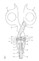
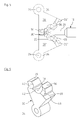
- FIGS. 1 and 2 show a control panel of a medical instrument, which forms the proximal end of the instrument.
- the medical instrument is an endoscopic shaft instrument.
- the control unit has a connection part 2, on which two grip parts 4a and 4b are articulated.
- an opening 6 is formed on the connecting part 2, which extends in the longitudinal direction of the connecting part 2 completely through this.
- Proximal material has the Druchbrechung 6 a section 8, starting from the proximal end of the connecting part 2 in the distal direction continuously rejuvenated.
- a cylindrical section 10 of the opening 6 closes distally to form a shoulder.
- Distal side of the portion 10 tapers through the opening 6 conical and merges into a section 12.
- a sleeve 14 is arranged in the sections 10 and 12, with a distal end section 16 of the sleeve 14 protruding distally from the connection part 2.
- the end portion 16 serves for attachment of a stem tube, not shown in the drawing, of the endoscopic shaft instrument.
- an actuator 18 is guided in the form of a train-pressure rod.
- the actuating element 18 is axially displaceable in the shaft tube and in the connecting part 2. Not visible from the drawing, the actuating element 18 extends through the entire shaft tube and is coupled in the region of the distal end of the instrument with a movably arranged there tool.
- the actuating element 18 has a section 20 with a cross-section that is narrower than the rest of the actuating element 18.
- the proximal end of the actuating element 18 forms a spherical extension 22, which adjoins the portion 20 of the actuating element 18.
- two hinge pins 24 are arranged at a distance from each other in the immediate vicinity of the proximal end of the connection part 2. At these two hinge pins 24, the handle parts 4a and 4b are pivotally hinged to the connector part 2.
- the grip parts 4a and 4b are each formed as a two-part lever. They each have a manually engageable lever arm 26 and a lever arm 28.
- the lever arms 28 of the handle parts 4a and 4b are each in Aligned substantially in the direction of the hinge pin 24, on which the respective other grip part 4a and 4b is articulated. In this respect, the lever arms 28 of the two handle parts 4a and 4b between the hinge pins 24 are aligned with each other.
- the lever arms 28 of the two grip parts 4a and 4b are directly coupled with each other in a movement-related manner.
- the lever arms 28 each have a toothing on the mutually facing sides, wherein the two toothings are engaged with one another.
- the teeth are formed by gear segments 30 which are integrated in recesses 32 of the lever arms 28.
- Fig. 2 has been omitted for reasons of clarity on the presentation of the gears. These are but from the Fig. 3 - 9 clear.
- the gear segments 30 have substantially the shape of a circular sector with an arcuate outer side on which the toothing is formed and two outgoing from the arcuate outer side tapered straight outer sides, at the ends of a bearing eye 34 is formed, which serves to receive a hinge pin 24 ,
- the tapered outer sides of the gear segments 30 enclose an angle of 65 °.
- the toothing of the gear segments 30 is asymmetrical and is formed by two teeth 36 and two tooth gaps 38.
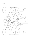
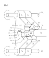
- two gear segments 30 are arranged one above the other, wherein a first gear segment 30 is arranged to a second gear segment 30 'rotated by 180 °, so that there, where there is a tooth gap 38 of the first gear segment 30, a Tooth 36 'of the second gear segment 30' is arranged and where there is a tooth 36 of the first gear segment 30, a tooth gap 38 'of the second gear segment 30' is arranged, which in particular from FIGS. 6 to 8 becomes clear.
- the respectively arranged in the lever arms 28 gear segments 30 and 3ß0 ' are all of identical design, so identical
- the lever arms 28 are coupled via the gear segments 30 and 30 'also directly to the actuating element 18.
- the actuator 18 between the oppositely arranged and mutually engaged gear segments 30 and 30 'out.
- recesses 40 are formed on the gear segments 30 and 30 'on their teeth 36 and 36', starting from a flat side of the gear segments 30 and 30 'and extending substantially over the entire tooth height of the teeth 36 and 36' ( Fig. 9 ).
- a further recess 42 is formed on each of the gear segments 30 and 30 'whose inner contour corresponds to the outer contour of the spherical extension 22 of the actuating element 18.
- the recesses 42 of the superimposed gear segments 30 and 30 'of the gear segment pairs of the lever 28 has a substantially spherical receiving space in which the spherical extension 22 of the actuating element 18 is arranged in a form-fitting manner.
- Fig. 6 to 8 The mode of operation of the medical instrument according to the invention is made in particular from Fig. 6 to 8 clear.
Landscapes
- Health & Medical Sciences (AREA)
- Life Sciences & Earth Sciences (AREA)
- Surgery (AREA)
- Animal Behavior & Ethology (AREA)
- Public Health (AREA)
- Engineering & Computer Science (AREA)
- Biomedical Technology (AREA)
- Heart & Thoracic Surgery (AREA)
- Medical Informatics (AREA)
- Molecular Biology (AREA)
- Veterinary Medicine (AREA)
- General Health & Medical Sciences (AREA)
- Nuclear Medicine, Radiotherapy & Molecular Imaging (AREA)
- Ophthalmology & Optometry (AREA)
- Physics & Mathematics (AREA)
- Biophysics (AREA)
- Optics & Photonics (AREA)
- Pathology (AREA)
- Radiology & Medical Imaging (AREA)
- Surgical Instruments (AREA)
- Infusion, Injection, And Reservoir Apparatuses (AREA)
Applications Claiming Priority (1)
| Application Number | Priority Date | Filing Date | Title |
|---|---|---|---|
| DE102011088003A DE102011088003A1 (de) | 2011-12-08 | 2011-12-08 | Medizinisches Instrument |
Publications (2)
| Publication Number | Publication Date |
|---|---|
| EP2601895A1 true EP2601895A1 (fr) | 2013-06-12 |
| EP2601895B1 EP2601895B1 (fr) | 2015-08-12 |
Family
ID=47278138
Family Applications (1)
| Application Number | Title | Priority Date | Filing Date |
|---|---|---|---|
| EP12193321.2A Active EP2601895B1 (fr) | 2011-12-08 | 2012-11-20 | Instrument médical |
Country Status (5)
| Country | Link |
|---|---|
| US (1) | US8926599B2 (fr) |
| EP (1) | EP2601895B1 (fr) |
| JP (1) | JP6055664B2 (fr) |
| CN (1) | CN103156669B (fr) |
| DE (1) | DE102011088003A1 (fr) |
Cited By (2)
| Publication number | Priority date | Publication date | Assignee | Title |
|---|---|---|---|---|
| EP2996620A4 (fr) * | 2013-05-15 | 2017-11-08 | Intuitive Surgical Operations, Inc. | Mécanisme de transmission de force pour instrument chirurgical téléopéré |
| CN110403669A (zh) * | 2019-07-31 | 2019-11-05 | 上海交通大学医学院附属仁济医院 | 一种用于微创腔镜手术的多自由度手术器械 |
Families Citing this family (4)
| Publication number | Priority date | Publication date | Assignee | Title |
|---|---|---|---|---|
| DE102013211368B4 (de) | 2013-06-18 | 2024-02-22 | Richard Wolf Gmbh | Endoskopisches Schaftinstrument |
| US12551203B2 (en) | 2018-12-28 | 2026-02-17 | Cellapax Corporation | Catheter with vessel lining for cell collection and methods for using same |
| CN110051410B (zh) * | 2019-05-15 | 2022-02-22 | 成都五义医疗科技有限公司 | 一种可拆洗重用的细长轴组件及其手术器械 |
| DE102023122446A1 (de) * | 2023-08-22 | 2025-02-27 | Aesculap Ag | Schmetterlingsgriff eines chirurgischen Handinstruments |
Citations (4)
| Publication number | Priority date | Publication date | Assignee | Title |
|---|---|---|---|---|
| DE665208C (de) | 1936-12-08 | 1938-09-20 | Ernst Axel Johan Ericsson | Gipsverbandschere |
| US5176699A (en) * | 1991-06-05 | 1993-01-05 | Harold Markham | Surgical device with double jaw actuation |
| FR2688681A1 (fr) | 1992-03-23 | 1993-09-24 | Lebosse Guy | Manche universel pour instrumentation de cóoeliochirurgie. |
| US6425906B1 (en) * | 1998-01-19 | 2002-07-30 | Michael John Radley Young | Ultrasonic cutting tool |
Family Cites Families (14)
| Publication number | Priority date | Publication date | Assignee | Title |
|---|---|---|---|---|
| CA1134701A (fr) * | 1977-10-17 | 1982-11-02 | David T. Green | Applicateur d'agrafes chirurgicales |
| US5282806A (en) * | 1992-08-21 | 1994-02-01 | Habley Medical Technology Corporation | Endoscopic surgical instrument having a removable, rotatable, end effector assembly |
| WO1994000059A1 (fr) * | 1992-06-24 | 1994-01-06 | Microsurge, Inc. | Instrument chirurgical endoscopique reutilisable |
| DE19508186C2 (de) * | 1995-03-09 | 1998-01-15 | Stefan Koscher | Chirurgisches Instrument |
| US5700270A (en) * | 1995-10-20 | 1997-12-23 | United States Surgical Corporation | Surgical clip applier |
| US20060287641A1 (en) * | 2005-06-16 | 2006-12-21 | Alfred Perlin | Laparoscopic surgical instrument for in situ tool exchange |
| DE602007008964D1 (de) * | 2006-02-01 | 2010-10-21 | Arthrex Inc | Griff für chirurgische Instrumente |
| US9561045B2 (en) * | 2006-06-13 | 2017-02-07 | Intuitive Surgical Operations, Inc. | Tool with rotation lock |
| WO2008008441A2 (fr) * | 2006-07-12 | 2008-01-17 | Nelson Drew V | Instrument chirurgical multifonctionnel |
| DE102006038515A1 (de) * | 2006-08-17 | 2008-02-21 | Karl Storz Gmbh & Co. Kg | Medizinisches Rohrschaftinstrument |
| DE202007000427U1 (de) * | 2007-01-08 | 2007-03-08 | Aesculap Ag & Co. Kg | Chirurgischer Haltegriff und chirurgisches Instrument |
| US8728057B2 (en) * | 2009-06-04 | 2014-05-20 | Adapta Medical, Inc. | Devices and methods for catheter advancement |
| DK2515770T3 (en) * | 2009-12-22 | 2019-02-25 | Cook Medical Technologies Llc | MEDICAL DEVICES WITH REMOVABLE THREADABLE BUYERS |
| CN102247180B (zh) * | 2011-06-30 | 2013-01-02 | 李宝童 | 医用持针钳 |
-
2011
- 2011-12-08 DE DE102011088003A patent/DE102011088003A1/de not_active Withdrawn
-
2012
- 2012-11-20 EP EP12193321.2A patent/EP2601895B1/fr active Active
- 2012-12-04 JP JP2012265341A patent/JP6055664B2/ja active Active
- 2012-12-05 US US13/705,796 patent/US8926599B2/en active Active
- 2012-12-10 CN CN201210528384.5A patent/CN103156669B/zh active Active
Patent Citations (4)
| Publication number | Priority date | Publication date | Assignee | Title |
|---|---|---|---|---|
| DE665208C (de) | 1936-12-08 | 1938-09-20 | Ernst Axel Johan Ericsson | Gipsverbandschere |
| US5176699A (en) * | 1991-06-05 | 1993-01-05 | Harold Markham | Surgical device with double jaw actuation |
| FR2688681A1 (fr) | 1992-03-23 | 1993-09-24 | Lebosse Guy | Manche universel pour instrumentation de cóoeliochirurgie. |
| US6425906B1 (en) * | 1998-01-19 | 2002-07-30 | Michael John Radley Young | Ultrasonic cutting tool |
Cited By (2)
| Publication number | Priority date | Publication date | Assignee | Title |
|---|---|---|---|---|
| EP2996620A4 (fr) * | 2013-05-15 | 2017-11-08 | Intuitive Surgical Operations, Inc. | Mécanisme de transmission de force pour instrument chirurgical téléopéré |
| CN110403669A (zh) * | 2019-07-31 | 2019-11-05 | 上海交通大学医学院附属仁济医院 | 一种用于微创腔镜手术的多自由度手术器械 |
Also Published As
| Publication number | Publication date |
|---|---|
| CN103156669A (zh) | 2013-06-19 |
| US20130150665A1 (en) | 2013-06-13 |
| JP2013119036A (ja) | 2013-06-17 |
| JP6055664B2 (ja) | 2016-12-27 |
| CN103156669B (zh) | 2016-09-07 |
| EP2601895B1 (fr) | 2015-08-12 |
| US8926599B2 (en) | 2015-01-06 |
| DE102011088003A1 (de) | 2013-06-13 |
Similar Documents
| Publication | Publication Date | Title |
|---|---|---|
| EP2696741B1 (fr) | Dispositif de commande | |
| EP2601895B1 (fr) | Instrument médical | |
| EP3175801B1 (fr) | Instrument médical | |
| DE102009042491A1 (de) | Chirurgisches Instrument | |
| DE102009042150A1 (de) | Chirurgisches Instrument | |
| EP3076882A1 (fr) | Instrument, en particulier instrument médical-endoscopique ou technoscope | |
| EP3012924A1 (fr) | Pince de pression | |
| EP3175802B1 (fr) | Instrument médical | |
| DE102021119386A1 (de) | Abwinkelbarer Schaft für ein medizinisches Handinstrument | |
| DE102014217796B4 (de) | Instrument, insbesondere medizinisch-endoskopisches Instrument oder Technoskop | |
| EP3695793B1 (fr) | Instrument médical | |
| WO2014124846A1 (fr) | Instrument, en particulier instrument médical d'endoscopie ou technoscope | |
| EP1721577B1 (fr) | Instrument endoscopique | |
| DE102014219195A1 (de) | Instrument, insbesondere medizinisch-endoskopisches Schaftinstrument | |
| DE102014206930B4 (de) | Instrument, insbesondere medizinisch-endoskopisches Instrument | |
| EP2653122B1 (fr) | Outil pour un instrument médical | |
| DE102013207248A1 (de) | Instrument, insbesondere ein medizinisch endoskopisches Instrument oder Technoskop | |
| DE4444025C2 (de) | Betätigungselement für eine medizinische Zange und dessen Verwendung in einer medizinischen Zange | |
| EP2403418B1 (fr) | Instrument médical | |
| DE202007000427U1 (de) | Chirurgischer Haltegriff und chirurgisches Instrument | |
| DE102021119526A1 (de) | Chirurgisches Instrument und Lenkgetriebe dafür | |
| DE102013003316B4 (de) | Chirurgisches Maulinstrument | |
| DE10145107A1 (de) | Füllstab für Endoskope | |
| EP2898818B1 (fr) | Instrument endoscopique | |
| DE10136963B4 (de) | Chirurgisches Instrument |
Legal Events
| Date | Code | Title | Description |
|---|---|---|---|
| PUAI | Public reference made under article 153(3) epc to a published international application that has entered the european phase |
Free format text: ORIGINAL CODE: 0009012 |
|
| AK | Designated contracting states |
Kind code of ref document: A1 Designated state(s): AL AT BE BG CH CY CZ DE DK EE ES FI FR GB GR HR HU IE IS IT LI LT LU LV MC MK MT NL NO PL PT RO RS SE SI SK SM TR |
|
| AX | Request for extension of the european patent |
Extension state: BA ME |
|
| 17P | Request for examination filed |
Effective date: 20131128 |
|
| RBV | Designated contracting states (corrected) |
Designated state(s): AL AT BE BG CH CY CZ DE DK EE ES FI FR GB GR HR HU IE IS IT LI LT LU LV MC MK MT NL NO PL PT RO RS SE SI SK SM TR |
|
| GRAP | Despatch of communication of intention to grant a patent |
Free format text: ORIGINAL CODE: EPIDOSNIGR1 |
|
| INTG | Intention to grant announced |
Effective date: 20150316 |
|
| GRAS | Grant fee paid |
Free format text: ORIGINAL CODE: EPIDOSNIGR3 |
|
| GRAA | (expected) grant |
Free format text: ORIGINAL CODE: 0009210 |
|
| AK | Designated contracting states |
Kind code of ref document: B1 Designated state(s): AL AT BE BG CH CY CZ DE DK EE ES FI FR GB GR HR HU IE IS IT LI LT LU LV MC MK MT NL NO PL PT RO RS SE SI SK SM TR |
|
| REG | Reference to a national code |
Ref country code: GB Ref legal event code: FG4D Free format text: NOT ENGLISH |
|
| REG | Reference to a national code |
Ref country code: CH Ref legal event code: EP |
|
| REG | Reference to a national code |
Ref country code: AT Ref legal event code: REF Ref document number: 741402 Country of ref document: AT Kind code of ref document: T Effective date: 20150815 |
|
| REG | Reference to a national code |
Ref country code: IE Ref legal event code: FG4D Free format text: LANGUAGE OF EP DOCUMENT: GERMAN |
|
| REG | Reference to a national code |
Ref country code: DE Ref legal event code: R096 Ref document number: 502012004092 Country of ref document: DE |
|
| REG | Reference to a national code |
Ref country code: FR Ref legal event code: PLFP Year of fee payment: 4 |
|
| REG | Reference to a national code |
Ref country code: CH Ref legal event code: NV Representative=s name: ISLER AND PEDRAZZINI AG, CH |
|
| REG | Reference to a national code |
Ref country code: LT Ref legal event code: MG4D |
|
| REG | Reference to a national code |
Ref country code: NL Ref legal event code: FP |
|
| PG25 | Lapsed in a contracting state [announced via postgrant information from national office to epo] |
Ref country code: LT Free format text: LAPSE BECAUSE OF FAILURE TO SUBMIT A TRANSLATION OF THE DESCRIPTION OR TO PAY THE FEE WITHIN THE PRESCRIBED TIME-LIMIT Effective date: 20150812 Ref country code: FI Free format text: LAPSE BECAUSE OF FAILURE TO SUBMIT A TRANSLATION OF THE DESCRIPTION OR TO PAY THE FEE WITHIN THE PRESCRIBED TIME-LIMIT Effective date: 20150812 Ref country code: GR Free format text: LAPSE BECAUSE OF FAILURE TO SUBMIT A TRANSLATION OF THE DESCRIPTION OR TO PAY THE FEE WITHIN THE PRESCRIBED TIME-LIMIT Effective date: 20151113 Ref country code: NO Free format text: LAPSE BECAUSE OF FAILURE TO SUBMIT A TRANSLATION OF THE DESCRIPTION OR TO PAY THE FEE WITHIN THE PRESCRIBED TIME-LIMIT Effective date: 20151112 Ref country code: LV Free format text: LAPSE BECAUSE OF FAILURE TO SUBMIT A TRANSLATION OF THE DESCRIPTION OR TO PAY THE FEE WITHIN THE PRESCRIBED TIME-LIMIT Effective date: 20150812 |
|
| PG25 | Lapsed in a contracting state [announced via postgrant information from national office to epo] |
Ref country code: IS Free format text: LAPSE BECAUSE OF FAILURE TO SUBMIT A TRANSLATION OF THE DESCRIPTION OR TO PAY THE FEE WITHIN THE PRESCRIBED TIME-LIMIT Effective date: 20151212 Ref country code: HR Free format text: LAPSE BECAUSE OF FAILURE TO SUBMIT A TRANSLATION OF THE DESCRIPTION OR TO PAY THE FEE WITHIN THE PRESCRIBED TIME-LIMIT Effective date: 20150812 Ref country code: PL Free format text: LAPSE BECAUSE OF FAILURE TO SUBMIT A TRANSLATION OF THE DESCRIPTION OR TO PAY THE FEE WITHIN THE PRESCRIBED TIME-LIMIT Effective date: 20150812 Ref country code: PT Free format text: LAPSE BECAUSE OF FAILURE TO SUBMIT A TRANSLATION OF THE DESCRIPTION OR TO PAY THE FEE WITHIN THE PRESCRIBED TIME-LIMIT Effective date: 20151214 Ref country code: ES Free format text: LAPSE BECAUSE OF FAILURE TO SUBMIT A TRANSLATION OF THE DESCRIPTION OR TO PAY THE FEE WITHIN THE PRESCRIBED TIME-LIMIT Effective date: 20150812 Ref country code: RS Free format text: LAPSE BECAUSE OF FAILURE TO SUBMIT A TRANSLATION OF THE DESCRIPTION OR TO PAY THE FEE WITHIN THE PRESCRIBED TIME-LIMIT Effective date: 20150812 Ref country code: SE Free format text: LAPSE BECAUSE OF FAILURE TO SUBMIT A TRANSLATION OF THE DESCRIPTION OR TO PAY THE FEE WITHIN THE PRESCRIBED TIME-LIMIT Effective date: 20150812 |
|
| PG25 | Lapsed in a contracting state [announced via postgrant information from national office to epo] |
Ref country code: IT Free format text: LAPSE BECAUSE OF FAILURE TO SUBMIT A TRANSLATION OF THE DESCRIPTION OR TO PAY THE FEE WITHIN THE PRESCRIBED TIME-LIMIT Effective date: 20150812 Ref country code: EE Free format text: LAPSE BECAUSE OF FAILURE TO SUBMIT A TRANSLATION OF THE DESCRIPTION OR TO PAY THE FEE WITHIN THE PRESCRIBED TIME-LIMIT Effective date: 20150812 Ref country code: SK Free format text: LAPSE BECAUSE OF FAILURE TO SUBMIT A TRANSLATION OF THE DESCRIPTION OR TO PAY THE FEE WITHIN THE PRESCRIBED TIME-LIMIT Effective date: 20150812 Ref country code: DK Free format text: LAPSE BECAUSE OF FAILURE TO SUBMIT A TRANSLATION OF THE DESCRIPTION OR TO PAY THE FEE WITHIN THE PRESCRIBED TIME-LIMIT Effective date: 20150812 |
|
| REG | Reference to a national code |
Ref country code: DE Ref legal event code: R097 Ref document number: 502012004092 Country of ref document: DE |
|
| PG25 | Lapsed in a contracting state [announced via postgrant information from national office to epo] |
Ref country code: RO Free format text: LAPSE BECAUSE OF FAILURE TO SUBMIT A TRANSLATION OF THE DESCRIPTION OR TO PAY THE FEE WITHIN THE PRESCRIBED TIME-LIMIT Effective date: 20150812 |
|
| PLBE | No opposition filed within time limit |
Free format text: ORIGINAL CODE: 0009261 |
|
| STAA | Information on the status of an ep patent application or granted ep patent |
Free format text: STATUS: NO OPPOSITION FILED WITHIN TIME LIMIT |
|
| PG25 | Lapsed in a contracting state [announced via postgrant information from national office to epo] |
Ref country code: MC Free format text: LAPSE BECAUSE OF FAILURE TO SUBMIT A TRANSLATION OF THE DESCRIPTION OR TO PAY THE FEE WITHIN THE PRESCRIBED TIME-LIMIT Effective date: 20150812 |
|
| 26N | No opposition filed |
Effective date: 20160513 |
|
| REG | Reference to a national code |
Ref country code: IE Ref legal event code: MM4A |
|
| PG25 | Lapsed in a contracting state [announced via postgrant information from national office to epo] |
Ref country code: SI Free format text: LAPSE BECAUSE OF FAILURE TO SUBMIT A TRANSLATION OF THE DESCRIPTION OR TO PAY THE FEE WITHIN THE PRESCRIBED TIME-LIMIT Effective date: 20150812 |
|
| REG | Reference to a national code |
Ref country code: FR Ref legal event code: PLFP Year of fee payment: 5 |
|
| PG25 | Lapsed in a contracting state [announced via postgrant information from national office to epo] |
Ref country code: IE Free format text: LAPSE BECAUSE OF NON-PAYMENT OF DUE FEES Effective date: 20151120 |
|
| PG25 | Lapsed in a contracting state [announced via postgrant information from national office to epo] |
Ref country code: BG Free format text: LAPSE BECAUSE OF FAILURE TO SUBMIT A TRANSLATION OF THE DESCRIPTION OR TO PAY THE FEE WITHIN THE PRESCRIBED TIME-LIMIT Effective date: 20150812 Ref country code: HU Free format text: LAPSE BECAUSE OF FAILURE TO SUBMIT A TRANSLATION OF THE DESCRIPTION OR TO PAY THE FEE WITHIN THE PRESCRIBED TIME-LIMIT; INVALID AB INITIO Effective date: 20121120 Ref country code: SM Free format text: LAPSE BECAUSE OF FAILURE TO SUBMIT A TRANSLATION OF THE DESCRIPTION OR TO PAY THE FEE WITHIN THE PRESCRIBED TIME-LIMIT Effective date: 20150812 |
|
| PG25 | Lapsed in a contracting state [announced via postgrant information from national office to epo] |
Ref country code: CY Free format text: LAPSE BECAUSE OF FAILURE TO SUBMIT A TRANSLATION OF THE DESCRIPTION OR TO PAY THE FEE WITHIN THE PRESCRIBED TIME-LIMIT Effective date: 20150812 |
|
| PG25 | Lapsed in a contracting state [announced via postgrant information from national office to epo] |
Ref country code: MT Free format text: LAPSE BECAUSE OF FAILURE TO SUBMIT A TRANSLATION OF THE DESCRIPTION OR TO PAY THE FEE WITHIN THE PRESCRIBED TIME-LIMIT Effective date: 20150812 |
|
| REG | Reference to a national code |
Ref country code: FR Ref legal event code: PLFP Year of fee payment: 6 |
|
| PG25 | Lapsed in a contracting state [announced via postgrant information from national office to epo] |
Ref country code: MK Free format text: LAPSE BECAUSE OF FAILURE TO SUBMIT A TRANSLATION OF THE DESCRIPTION OR TO PAY THE FEE WITHIN THE PRESCRIBED TIME-LIMIT Effective date: 20150812 Ref country code: TR Free format text: LAPSE BECAUSE OF FAILURE TO SUBMIT A TRANSLATION OF THE DESCRIPTION OR TO PAY THE FEE WITHIN THE PRESCRIBED TIME-LIMIT Effective date: 20150812 |
|
| PG25 | Lapsed in a contracting state [announced via postgrant information from national office to epo] |
Ref country code: AL Free format text: LAPSE BECAUSE OF FAILURE TO SUBMIT A TRANSLATION OF THE DESCRIPTION OR TO PAY THE FEE WITHIN THE PRESCRIBED TIME-LIMIT Effective date: 20150812 |
|
| PGFP | Annual fee paid to national office [announced via postgrant information from national office to epo] |
Ref country code: LU Payment date: 20231120 Year of fee payment: 12 |
|
| PGFP | Annual fee paid to national office [announced via postgrant information from national office to epo] |
Ref country code: BE Payment date: 20241119 Year of fee payment: 13 |
|
| PGFP | Annual fee paid to national office [announced via postgrant information from national office to epo] |
Ref country code: GB Payment date: 20241121 Year of fee payment: 13 |
|
| PGFP | Annual fee paid to national office [announced via postgrant information from national office to epo] |
Ref country code: FR Payment date: 20241122 Year of fee payment: 13 |
|
| PGFP | Annual fee paid to national office [announced via postgrant information from national office to epo] |
Ref country code: AT Payment date: 20241118 Year of fee payment: 13 |
|
| PGFP | Annual fee paid to national office [announced via postgrant information from national office to epo] |
Ref country code: CZ Payment date: 20241108 Year of fee payment: 13 |
|
| PGFP | Annual fee paid to national office [announced via postgrant information from national office to epo] |
Ref country code: CH Payment date: 20241201 Year of fee payment: 13 |
|
| PG25 | Lapsed in a contracting state [announced via postgrant information from national office to epo] |
Ref country code: LU Free format text: LAPSE BECAUSE OF NON-PAYMENT OF DUE FEES Effective date: 20241120 |
|
| PGFP | Annual fee paid to national office [announced via postgrant information from national office to epo] |
Ref country code: NL Payment date: 20251119 Year of fee payment: 14 |
|
| PGFP | Annual fee paid to national office [announced via postgrant information from national office to epo] |
Ref country code: DE Payment date: 20251128 Year of fee payment: 14 |