EP2602182B1 - Vorrichtung zur Befestigung von Tragflächenpaneelen - Google Patents
Vorrichtung zur Befestigung von Tragflächenpaneelen Download PDFInfo
- Publication number
- EP2602182B1 EP2602182B1 EP12194697.4A EP12194697A EP2602182B1 EP 2602182 B1 EP2602182 B1 EP 2602182B1 EP 12194697 A EP12194697 A EP 12194697A EP 2602182 B1 EP2602182 B1 EP 2602182B1
- Authority
- EP
- European Patent Office
- Prior art keywords
- aerodynamic structure
- fixed aerodynamic
- shroud panel
- aircraft
- structure assembly
- Prior art date
- Legal status (The legal status is an assumption and is not a legal conclusion. Google has not performed a legal analysis and makes no representation as to the accuracy of the status listed.)
- Active
Links
Images

Classifications
-
- B—PERFORMING OPERATIONS; TRANSPORTING
- B64—AIRCRAFT; AVIATION; COSMONAUTICS
- B64C—AEROPLANES; HELICOPTERS
- B64C1/00—Fuselages; Constructional features common to fuselages, wings, stabilising surfaces or the like
-
- B—PERFORMING OPERATIONS; TRANSPORTING
- B64—AIRCRAFT; AVIATION; COSMONAUTICS
- B64C—AEROPLANES; HELICOPTERS
- B64C3/00—Wings
- B64C3/28—Leading or trailing edges attached to primary structures, e.g. forming fixed slots
Definitions
- the present invention is concerned with apparatus for attachment of panels to aircraft aerodynamic structures. More specifically, the present invention is concerned with an apparatus for attaching shroud panels to the trailing edge of aircraft wing covers.
- Known aircraft aerodynamic structures such as wings and stabilisers comprise a rear spar, abutted on its top and bottom surfaces by upper and lower skins or covers.
- wings and stabilisers are provided with shroud panels, which extend rearward of the spar and act as a continuation of the skins.
- an aircraft fixed aerodynamic structure assembly according to claim 1.
- aircraft fixed aerodynamic structure we mean a structure of the aircraft attached to the fuselage which controls or influences flight, such as an aircraft wing, vertical stabiliser or horizontal stabiliser.
- the attachment members pivot at one or both ends, and are provided as pivoting butt straps.
- pivoting butt straps allows relative movement between adjacent locations on the shroud panel and wing or stabiliser. Therefore the stresses produced in both parts by any strain differential resulting from thermal or force effects are reduced.
- attachment members are pivotably connected to both the shroud panel and aerodynamic structure component.
- At least one of the butt straps has a range of motion limited by an abutment with the shroud panel or the wing trailing edge component. This may be defined by a shoulder formed in the butt strap, which may also act to keep the outer wing surface flush.
- the shroud panel and the wing trailing edge component are also attached by a non-pivotable butt strap, being rotationally fixed to the shroud panel and trailing edge component. This takes any side load, whilst allowing relative expansion / contraction.
- non-pivotable butt strap is located in substantially the spanwise centre of the shroud panel.
- a plurality of pivotable putt straps may be provided on either spanwise side of the non-pivotable butt strap.
- a spoiler rib extending from the trailing edge of the wing, which spoiler rib is connected to the shroud panel at a trailing edge thereof.
- the spoiler rib and shroud panel are connected by a strut, which strut extends in a vertical spanwise plane in use.
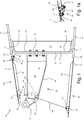
- a wing trailing edge assembly 10 comprises a rear spar 12 which runs in a spanwise direction along the wing.
- the rear spar comprises a vertical plate 14 and two forwardly depending flanges 16, 18 at the top and bottom thereof.
- the flanges 16, 18 are tapered slightly to diverge in a forward direction.
- the rear spar 12 therefore defines a forward facing concavity.
- a stiffener 20 is provided against the forward facing side of the spar 12.
- the stiffener 20 comprises a main plate 22 extending vertically and in a chordwise direction.
- a peripheral flange 24 runs around the edge of the main plate 22 giving it a cup-like shape.
- the plate 22 tapers outwardly in a forward direction and is nested within the concavity formed by the spar 12.
- an upper wing skin 26 is provided which has a small overhang 28 over the rear of the spar 12.
- the overhang defines a number of bores 30 equally spaced in a spanwise direction (see Figure 2 ).
- a lower wing skin 27 extends over the lower part of the rib 12 in a similar manner, having an overhang 29.
- a first spoiler rib 32 extends from the rear of the spar 12.
- the rib 32 defines a lug 34 at a first end which is connected to a dogleg portion 36 and then to a main beam 38.
- an attachment portion 40 is defined whereby the rib 32 is bolted to the spar 12 and stiffener 20.
- a spoiler (not shown) is pivotably attached to the lug 34.
- the rib 32 is generally constructed as a chordwise vertical plate 42 having a peripheral flange 44 extending in a spanwise direction for structural rigidity.
- a second spolier rib 46 is also provided.
- the second spoiler rib 46 is a mirror image of the first rib 32 and the plates 42 are offset by a distance d.
- the flanges 44 extend in opposite directions.
- a rib attachment plate 46 is provided extending between the ribs 32, 46.
- the rib attachment plate 46 has a vertical spanwise plate 48 having two side flanges 50, 52 which are bolted to the ribs 32, 46 respectively.
- the plate 48 extends to a double pivot mount 54 defining a first bore 56 and a second bore 58.
- an upper shroud panel 60, and lower shroud panel 62 are provided. Both shroud panels are attached to, and extend from the skin overhangs 28, 29 respectively.
- the lower shroud panel comprises a plate like extension 64 of the wing skin 27 having stiffening ribs 66 defined thereon. Proximate the end opposite the wing skin overhang 29, the panel defines an attachment lug 68 defining a bore 70.
- the upper shroud panel 60 also comprises a plate like extension 72 of the upper wing skin 26 having a number of stiffening ribs 74 defined thereon. At a first end of the panel 60, a row of bores 76 are defined, equally spaced in a spanwise direction. The locations of the bores 76 match those of the bores 30 on the upper wing skin overhang 28.
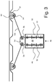
- the upper shroud panel 60 further defines a first strut attachment bracket 78 proximate the trailing edge thereof.
- the bracket comprises a plate 80 attached to the shroud panel 60, and a downwardly depending vertical spanwise flange 82 defining a bore 84 (see Figure 3 ).
- each butt strap 86 is obround in plan (as shown in Figure 2 ) and comprises a first attachment region 88 connected to a second attachment region 92 via a shoulder or step 90.
- the attachment regions 88, 92 define respective bores 94, 96.
- each strap 86 in an installed position, the first region 88 of each strap 86 is positioned such that the bore 94 aligns with one of the bores 30 on the wing skin overhang 28.
- a first fastener 98 is inserted in order to form a pivoting joint between the strap 86 and the overhang 28.
- each strap 86 is positioned such that the bore 96 aligns with one of the bores 76 on the shroud panel 60.
- a second fastener 100 is inserted in order to form a pivoting joint between the strap 86 and the shroud panel 60.
- the step in the straps 86 produced by the shoulder 90 accounts for the difference in thickness between the thick wing skin and the thinner shroud panel. By providing a step, the outer surfaces can be made flush.
- a plurality of straps 86 are used to attach the shroud panel 60 to the overhang 28.
- a central butt strap 102 is provided which is similar to the pivoting butt straps 86, but comprises a row of three bores on each side.
- the central butt strap is positioned at the spanwise centre of the shroud panel 60 with pivoting straps 86 either side.
- a lower strut 104 joins the attachment lug 68 of the lower shroud panel 62, via a pinned connection in the bore 70 to the main beam 38 of the rib 32, where it also pinned.
- the lower strut 104 extends in a fore-aft direction in a vertical chordwise plane.
- An upper strut 106 is pin joined to the upper shroud panel 60 at the bore 84 and extends to the bore 56 of the double pivot mount 54. It will be noted that the strut 106 extends in a vertical spanwise plane as shown in Figure 3 .
- each of the pivoting butt straps 86 can pivot about either attachment in order to allow relative deformation (under thermal or mechanical stresses) between the skin overhang 28 and the shroud panel 60.
- the degree of permitted relative deformation is determined in part by the geometry of the shoulder 90.
- the central strap 102 ensures that spanwise load can be taken by the structure without significant relative movement between the panels.
- the assembly as described above provides a stable structure for the reaction of the various forces experienced in flight.
- the ribs are arranged to support the shroud panels vertically (via the upper struts) whilst the panels support the ribs in a spanwise (lateral) sense though the struts. This functionality arises because the struts are angled in the vertical spanwise plane and in compression have both a vertical and horizontal (spanwise) load carry capacity.
- pivoting but straps may be connected to any other suitable component, not just the wing skin overhang.
- butt straps are simple components which are inexpensive and easily replaced, as well as providing multiple redundancy.
- the rib may be any other kind of rib, not just a spoiler rib.
Landscapes
- Engineering & Computer Science (AREA)
- Mechanical Engineering (AREA)
- Aviation & Aerospace Engineering (AREA)
- Body Structure For Vehicles (AREA)
- Connection Of Plates (AREA)
- Specific Sealing Or Ventilating Devices For Doors And Windows (AREA)
- Lining Or Joining Of Plastics Or The Like (AREA)
- Shielding Devices Or Components To Electric Or Magnetic Fields (AREA)
Claims (12)
- Flugzeug-Aerodynamik-Feststrukturanordnung (10), umfassend:eine Aerodynamik-Feststrukturkomponente (26),ein Verkleidungspaneel (60),wobei das Verkleidungspaneel (60) auf der Aerodynamik-Feststrukturkomponente (26) durch eine Vielzahl von Anbringungselementen (86) angebracht ist, dadurch gekennzeichnet, dass jedes Anbringungselement (86) mit dem Verkleidungspaneel durch eine Gelenkverbindung (100) und mit der Aerodynamik-Feststrukturkomponente durch eine andere Gelenkverbindung (98) verbunden ist.
- Flugzeug-Aerodynamik-Feststrukturanordnung (10) nach Anspruch 1, bei der die Gelenkverbindungen Drehgelenke sind.
- Flugzeug-Aerodynamik-Feststrukturanordnung (10) nach Anspruch 1 oder 2, bei der die Anbringungselemente Stoßlaschen (86) umfassend, von denen jede eine Aerodynamik-Feststrukturkomponenten-Formation an einem ersten Ende und eine Verkleidungspaneel-Formation an einem zweiten Ende aufweist.
- Flugzeug-Aerodynamik-Feststrukturanordnung (10) nach Anspruch 3, bei der wenigstens eine der Stoßlaschen (86) einen Bewegungsbereich aufweist, der durch ein Auflager (90) mit dem Verkleidungspaneel oder der Aerodynamik-Feststrukturkomponente limitiert ist.
- Flugzeug-Aerodynamik-Feststrukturanordnung (10) nach Anspruch 4, bei der das Auflager durch eine Schulter (90) definiert wird, die in der Stoßlasche ausgebildet ist.
- Flugzeug-Aerodynamik-Feststrukturanordnung (10) nach einem der vorherigen Ansprüche, bei der das Verkleidungspaneel und die Aerodynamik-Feststrukturkomponente zudem durch eine nicht-drehbare Stoßlasche (102) angebracht sind, die drehfest zum Verkleidungspaneel und zur Aerodynamik-Feststrukturkomponente ist.
- Flugzeug-Aerodynamik-Feststrukturanordnung (10) nach Anspruch 7, bei der die nicht-drehbare Stoßlasche (102) in der im Wesentlichen Spannweitenmitte des Verkleidungspaneels angeordnet ist.
- Flugzeug-Aerodynamik-Feststrukturanordnung (10) nach Anspruch 6 oder 7, bei der eine Vielzahl von drehbaren Stoßlaschen (86) an jeder Spannweitenseite des der nicht-drehbaren Stoßlasche (102) vorgesehen sind.
- Flugzeug-Aerodynamik-Feststrukturanordnung (10) nach einem der vorherigen Ansprüche, bei der die Aerodynamik-Feststrukturkomponente eine Flügel- oder Stabilisatorabdeckung oder ein Außenhautpaneel (26) ist, das von einer Hinter- oder Vorderkante des Flügels oder Stabilisators absteht.
- Flugzeug-Aerodynamik-Feststrukturanordnung (10) nach Anspruch 9, umfassend eine Spoilerrippe (28), die sich von der Hinterkante des Flügels oder Stabilisators erstreckt, welche Spoilerrippe mit dem Verkleidungspaneel an dessen Hinterkante verbunden ist.
- Flugzeug-Aerodynamik-Feststrukturanordnung (10) nach Anspruch 10, bei der die Spoilerrippe und das Verkleidungspaneel durch einen Holm verbunden sind.
- Flugzeug-Aerodynamik-Feststrukturanordnung (10) nach Anspruch 11, bei der sich der Holm im Gebrauch in einer vertikalen Spannenweitenebene erstreckt.
Applications Claiming Priority (1)
| Application Number | Priority Date | Filing Date | Title |
|---|---|---|---|
| GBGB1120996.2A GB201120996D0 (en) | 2011-12-07 | 2011-12-07 | Apparatus for attachment of wing panels |
Publications (2)
| Publication Number | Publication Date |
|---|---|
| EP2602182A1 EP2602182A1 (de) | 2013-06-12 |
| EP2602182B1 true EP2602182B1 (de) | 2018-05-30 |
Family
ID=45541314
Family Applications (1)
| Application Number | Title | Priority Date | Filing Date |
|---|---|---|---|
| EP12194697.4A Active EP2602182B1 (de) | 2011-12-07 | 2012-11-28 | Vorrichtung zur Befestigung von Tragflächenpaneelen |
Country Status (4)
| Country | Link |
|---|---|
| US (1) | US9334038B2 (de) |
| EP (1) | EP2602182B1 (de) |
| CN (1) | CN103144763B (de) |
| GB (1) | GB201120996D0 (de) |
Families Citing this family (6)
| Publication number | Priority date | Publication date | Assignee | Title |
|---|---|---|---|---|
| US20140059860A1 (en) * | 2012-08-15 | 2014-03-06 | Thomas Hsueh | Method of mating composite structures without the use of through-structure fasteners |
| US9156538B1 (en) | 2013-07-22 | 2015-10-13 | The Boeing Company | Aircraft skin attachment system |
| GB2605195B (en) | 2021-03-26 | 2023-12-13 | Airbus Operations Ltd | Trailing edge panel support with movable connector |
| GB2605194B (en) | 2021-03-26 | 2023-12-13 | Airbus Operations Ltd | Trailing edge panel support with biasing arrangement |
| GB2605197B (en) | 2021-03-26 | 2023-12-13 | Airbus Operations Ltd | Aircraft wing with trailing edge panel |
| GB2605196B (en) * | 2021-03-26 | 2024-01-10 | Airbus Operations Ltd | Trailing edge panel support |
Family Cites Families (14)
| Publication number | Priority date | Publication date | Assignee | Title |
|---|---|---|---|---|
| US4055041A (en) * | 1974-11-08 | 1977-10-25 | The United States Of America As Represented By The Administrator Of The National Aeronautics And Space Administration | Integrated gas turbine engine-nacelle |
| DE2804254C2 (de) | 1978-02-01 | 1985-02-07 | Grob, Burkhart, Dipl.-Ing. ETH, 8023 Großhesselohe | Tragflügel mit Klappe |
| GB0427957D0 (en) * | 2004-12-21 | 2005-01-26 | Airbus Uk Ltd | An aircraft wing |
| FR2911933B1 (fr) * | 2007-01-26 | 2009-05-01 | Snecma Sa | Dispositif d'assemblage de deux ensembles, par exemple pour stator de turbomachine |
| FR2926791B1 (fr) * | 2008-01-29 | 2010-05-28 | Aircelle Sa | Entree d'air pour nacelle d'aeronef, et ensemble propulsif comprenant une telle entree d'air |
| GB0803689D0 (en) | 2008-02-29 | 2008-04-09 | Airbus Uk Ltd | Trailing edge aircraft structure with overhaning cover |
| GB0803692D0 (en) * | 2008-02-29 | 2008-04-09 | Airbus Uk Ltd | Fitting for pivotally connecting aerodynamic control element to aircraft structure |
| GB0803690D0 (en) * | 2008-02-29 | 2008-04-09 | Airbus Uk Ltd | Aircraft structure with hinge rib assembly |
| GB0805963D0 (en) * | 2008-04-02 | 2008-05-07 | Airbus Uk Ltd | Aircraft structure |
| GB0901640D0 (en) * | 2009-02-03 | 2009-03-11 | Airbus Uk Ltd | Joint |
| GB0905818D0 (en) * | 2009-04-06 | 2009-05-20 | Airbus Uk Ltd | Coupling assembly |
| GB0911012D0 (en) * | 2009-06-25 | 2009-08-12 | Airbus Operations Ltd | Cross-bleed dam |
| GB0918750D0 (en) * | 2009-10-27 | 2009-12-09 | Airbus Uk Ltd | Cover trailing edge profile |
| GB201004757D0 (en) * | 2010-03-23 | 2010-05-05 | Airbus Operations Ltd | Joint |
-
2011
- 2011-12-07 GB GBGB1120996.2A patent/GB201120996D0/en not_active Ceased
-
2012
- 2012-11-28 EP EP12194697.4A patent/EP2602182B1/de active Active
- 2012-11-29 US US13/688,475 patent/US9334038B2/en active Active
- 2012-12-07 CN CN201210523539.6A patent/CN103144763B/zh not_active Expired - Fee Related
Non-Patent Citations (1)
| Title |
|---|
| None * |
Also Published As
| Publication number | Publication date |
|---|---|
| EP2602182A1 (de) | 2013-06-12 |
| CN103144763A (zh) | 2013-06-12 |
| CN103144763B (zh) | 2016-11-09 |
| US20130146712A1 (en) | 2013-06-13 |
| GB201120996D0 (en) | 2012-01-18 |
| US9334038B2 (en) | 2016-05-10 |
Similar Documents
| Publication | Publication Date | Title |
|---|---|---|
| EP2602182B1 (de) | Vorrichtung zur Befestigung von Tragflächenpaneelen | |
| US11352127B2 (en) | Wing tip device attachment apparatus and method | |
| US11247766B2 (en) | Leading edge structure | |
| US7887009B2 (en) | Methods and systems for attaching aircraft wings to fuselages | |
| US9248921B2 (en) | Method for mounting a pylon to an aircraft | |
| EP2602183B1 (de) | Flugzeugrippenanordnung | |
| JP5208115B2 (ja) | 胴体と主翼との間の自由な撓みを可能にする台形パネルのピン継手 | |
| US11192624B2 (en) | Aerofoil structure and method of assembly | |
| EP2772427B1 (de) | Vertikal integrierte Träger | |
| CN102442433B (zh) | 用于航空器发动机附连挂架的具有连接杆的结合有三个对齐的球窝接头的推动力吸收设备 | |
| KR102488781B1 (ko) | 핀 고정식 동체-날개 연결체 | |
| EP2415668B1 (de) | Verfahren zum Herstellen einer Verbindungsstruktur für eine Luftfahrzeugverkleidung | |
| US8371537B2 (en) | Aircraft structure with hinge rib assembly | |
| US20090218450A1 (en) | Fitting for pivotally connecting aerodynamic control element to aircraft structure | |
| US11905001B2 (en) | Wingtip to wing aircraft connection assembly | |
| JP7804468B2 (ja) | 航空機の中央ウィングボックスを隔壁に接続するためのコネクタ | |
| CN104724279A (zh) | 用于飞行器升力面的前缘 | |
| US20080001029A1 (en) | Fitting with torsion box, of plastic material reinforced with carbon fibre, for coupling a drive motor / spindle unit for trimming of a horizontal stabiliser of an aircraft | |
| CN113942652A (zh) | 具有机翼和发动机吊挂架的飞行器组件 | |
| US11260956B2 (en) | Leading edge slat with optimized structure | |
| US8256710B2 (en) | Live trim tabs | |
| EP3421354B1 (de) | Vorderkantenhüllenstruktur |
Legal Events
| Date | Code | Title | Description |
|---|---|---|---|
| PUAI | Public reference made under article 153(3) epc to a published international application that has entered the european phase |
Free format text: ORIGINAL CODE: 0009012 |
|
| AK | Designated contracting states |
Kind code of ref document: A1 Designated state(s): AL AT BE BG CH CY CZ DE DK EE ES FI FR GB GR HR HU IE IS IT LI LT LU LV MC MK MT NL NO PL PT RO RS SE SI SK SM TR |
|
| AX | Request for extension of the european patent |
Extension state: BA ME |
|
| 17P | Request for examination filed |
Effective date: 20140129 |
|
| RBV | Designated contracting states (corrected) |
Designated state(s): AL AT BE BG CH CY CZ DE DK EE ES FI FR GB GR HR HU IE IS IT LI LT LU LV MC MK MT NL NO PL PT RO RS SE SI SK SM TR |
|
| STAA | Information on the status of an ep patent application or granted ep patent |
Free format text: STATUS: EXAMINATION IS IN PROGRESS |
|
| 17Q | First examination report despatched |
Effective date: 20161020 |
|
| GRAP | Despatch of communication of intention to grant a patent |
Free format text: ORIGINAL CODE: EPIDOSNIGR1 |
|
| STAA | Information on the status of an ep patent application or granted ep patent |
Free format text: STATUS: GRANT OF PATENT IS INTENDED |
|
| INTG | Intention to grant announced |
Effective date: 20170802 |
|
| GRAJ | Information related to disapproval of communication of intention to grant by the applicant or resumption of examination proceedings by the epo deleted |
Free format text: ORIGINAL CODE: EPIDOSDIGR1 |
|
| STAA | Information on the status of an ep patent application or granted ep patent |
Free format text: STATUS: EXAMINATION IS IN PROGRESS |
|
| GRAP | Despatch of communication of intention to grant a patent |
Free format text: ORIGINAL CODE: EPIDOSNIGR1 |
|
| STAA | Information on the status of an ep patent application or granted ep patent |
Free format text: STATUS: GRANT OF PATENT IS INTENDED |
|
| INTC | Intention to grant announced (deleted) | ||
| INTG | Intention to grant announced |
Effective date: 20171213 |
|
| GRAS | Grant fee paid |
Free format text: ORIGINAL CODE: EPIDOSNIGR3 |
|
| GRAA | (expected) grant |
Free format text: ORIGINAL CODE: 0009210 |
|
| STAA | Information on the status of an ep patent application or granted ep patent |
Free format text: STATUS: THE PATENT HAS BEEN GRANTED |
|
| AK | Designated contracting states |
Kind code of ref document: B1 Designated state(s): AL AT BE BG CH CY CZ DE DK EE ES FI FR GB GR HR HU IE IS IT LI LT LU LV MC MK MT NL NO PL PT RO RS SE SI SK SM TR |
|
| REG | Reference to a national code |
Ref country code: GB Ref legal event code: FG4D |
|
| REG | Reference to a national code |
Ref country code: CH Ref legal event code: EP |
|
| REG | Reference to a national code |
Ref country code: AT Ref legal event code: REF Ref document number: 1003340 Country of ref document: AT Kind code of ref document: T Effective date: 20180615 |
|
| REG | Reference to a national code |
Ref country code: DE Ref legal event code: R096 Ref document number: 602012046828 Country of ref document: DE |
|
| REG | Reference to a national code |
Ref country code: IE Ref legal event code: FG4D |
|
| REG | Reference to a national code |
Ref country code: NL Ref legal event code: MP Effective date: 20180530 |
|
| REG | Reference to a national code |
Ref country code: LT Ref legal event code: MG4D |
|
| PG25 | Lapsed in a contracting state [announced via postgrant information from national office to epo] |
Ref country code: NO Free format text: LAPSE BECAUSE OF FAILURE TO SUBMIT A TRANSLATION OF THE DESCRIPTION OR TO PAY THE FEE WITHIN THE PRESCRIBED TIME-LIMIT Effective date: 20180830 Ref country code: ES Free format text: LAPSE BECAUSE OF FAILURE TO SUBMIT A TRANSLATION OF THE DESCRIPTION OR TO PAY THE FEE WITHIN THE PRESCRIBED TIME-LIMIT Effective date: 20180530 Ref country code: CY Free format text: LAPSE BECAUSE OF FAILURE TO SUBMIT A TRANSLATION OF THE DESCRIPTION OR TO PAY THE FEE WITHIN THE PRESCRIBED TIME-LIMIT Effective date: 20180530 Ref country code: LT Free format text: LAPSE BECAUSE OF FAILURE TO SUBMIT A TRANSLATION OF THE DESCRIPTION OR TO PAY THE FEE WITHIN THE PRESCRIBED TIME-LIMIT Effective date: 20180530 Ref country code: SE Free format text: LAPSE BECAUSE OF FAILURE TO SUBMIT A TRANSLATION OF THE DESCRIPTION OR TO PAY THE FEE WITHIN THE PRESCRIBED TIME-LIMIT Effective date: 20180530 Ref country code: FI Free format text: LAPSE BECAUSE OF FAILURE TO SUBMIT A TRANSLATION OF THE DESCRIPTION OR TO PAY THE FEE WITHIN THE PRESCRIBED TIME-LIMIT Effective date: 20180530 Ref country code: BG Free format text: LAPSE BECAUSE OF FAILURE TO SUBMIT A TRANSLATION OF THE DESCRIPTION OR TO PAY THE FEE WITHIN THE PRESCRIBED TIME-LIMIT Effective date: 20180830 |
|
| PG25 | Lapsed in a contracting state [announced via postgrant information from national office to epo] |
Ref country code: HR Free format text: LAPSE BECAUSE OF FAILURE TO SUBMIT A TRANSLATION OF THE DESCRIPTION OR TO PAY THE FEE WITHIN THE PRESCRIBED TIME-LIMIT Effective date: 20180530 Ref country code: RS Free format text: LAPSE BECAUSE OF FAILURE TO SUBMIT A TRANSLATION OF THE DESCRIPTION OR TO PAY THE FEE WITHIN THE PRESCRIBED TIME-LIMIT Effective date: 20180530 Ref country code: LV Free format text: LAPSE BECAUSE OF FAILURE TO SUBMIT A TRANSLATION OF THE DESCRIPTION OR TO PAY THE FEE WITHIN THE PRESCRIBED TIME-LIMIT Effective date: 20180530 Ref country code: GR Free format text: LAPSE BECAUSE OF FAILURE TO SUBMIT A TRANSLATION OF THE DESCRIPTION OR TO PAY THE FEE WITHIN THE PRESCRIBED TIME-LIMIT Effective date: 20180831 |
|
| REG | Reference to a national code |
Ref country code: AT Ref legal event code: MK05 Ref document number: 1003340 Country of ref document: AT Kind code of ref document: T Effective date: 20180530 |
|
| PG25 | Lapsed in a contracting state [announced via postgrant information from national office to epo] |
Ref country code: NL Free format text: LAPSE BECAUSE OF FAILURE TO SUBMIT A TRANSLATION OF THE DESCRIPTION OR TO PAY THE FEE WITHIN THE PRESCRIBED TIME-LIMIT Effective date: 20180530 |
|
| PG25 | Lapsed in a contracting state [announced via postgrant information from national office to epo] |
Ref country code: SK Free format text: LAPSE BECAUSE OF FAILURE TO SUBMIT A TRANSLATION OF THE DESCRIPTION OR TO PAY THE FEE WITHIN THE PRESCRIBED TIME-LIMIT Effective date: 20180530 Ref country code: PL Free format text: LAPSE BECAUSE OF FAILURE TO SUBMIT A TRANSLATION OF THE DESCRIPTION OR TO PAY THE FEE WITHIN THE PRESCRIBED TIME-LIMIT Effective date: 20180530 Ref country code: EE Free format text: LAPSE BECAUSE OF FAILURE TO SUBMIT A TRANSLATION OF THE DESCRIPTION OR TO PAY THE FEE WITHIN THE PRESCRIBED TIME-LIMIT Effective date: 20180530 Ref country code: DK Free format text: LAPSE BECAUSE OF FAILURE TO SUBMIT A TRANSLATION OF THE DESCRIPTION OR TO PAY THE FEE WITHIN THE PRESCRIBED TIME-LIMIT Effective date: 20180530 Ref country code: AT Free format text: LAPSE BECAUSE OF FAILURE TO SUBMIT A TRANSLATION OF THE DESCRIPTION OR TO PAY THE FEE WITHIN THE PRESCRIBED TIME-LIMIT Effective date: 20180530 Ref country code: CZ Free format text: LAPSE BECAUSE OF FAILURE TO SUBMIT A TRANSLATION OF THE DESCRIPTION OR TO PAY THE FEE WITHIN THE PRESCRIBED TIME-LIMIT Effective date: 20180530 Ref country code: RO Free format text: LAPSE BECAUSE OF FAILURE TO SUBMIT A TRANSLATION OF THE DESCRIPTION OR TO PAY THE FEE WITHIN THE PRESCRIBED TIME-LIMIT Effective date: 20180530 |
|
| PG25 | Lapsed in a contracting state [announced via postgrant information from national office to epo] |
Ref country code: SM Free format text: LAPSE BECAUSE OF FAILURE TO SUBMIT A TRANSLATION OF THE DESCRIPTION OR TO PAY THE FEE WITHIN THE PRESCRIBED TIME-LIMIT Effective date: 20180530 Ref country code: IT Free format text: LAPSE BECAUSE OF FAILURE TO SUBMIT A TRANSLATION OF THE DESCRIPTION OR TO PAY THE FEE WITHIN THE PRESCRIBED TIME-LIMIT Effective date: 20180530 |
|
| REG | Reference to a national code |
Ref country code: DE Ref legal event code: R097 Ref document number: 602012046828 Country of ref document: DE |
|
| PLBE | No opposition filed within time limit |
Free format text: ORIGINAL CODE: 0009261 |
|
| STAA | Information on the status of an ep patent application or granted ep patent |
Free format text: STATUS: NO OPPOSITION FILED WITHIN TIME LIMIT |
|
| 26N | No opposition filed |
Effective date: 20190301 |
|
| PG25 | Lapsed in a contracting state [announced via postgrant information from national office to epo] |
Ref country code: SI Free format text: LAPSE BECAUSE OF FAILURE TO SUBMIT A TRANSLATION OF THE DESCRIPTION OR TO PAY THE FEE WITHIN THE PRESCRIBED TIME-LIMIT Effective date: 20180530 |
|
| REG | Reference to a national code |
Ref country code: CH Ref legal event code: PL |
|
| PG25 | Lapsed in a contracting state [announced via postgrant information from national office to epo] |
Ref country code: MC Free format text: LAPSE BECAUSE OF FAILURE TO SUBMIT A TRANSLATION OF THE DESCRIPTION OR TO PAY THE FEE WITHIN THE PRESCRIBED TIME-LIMIT Effective date: 20180530 Ref country code: LU Free format text: LAPSE BECAUSE OF NON-PAYMENT OF DUE FEES Effective date: 20181128 |
|
| REG | Reference to a national code |
Ref country code: BE Ref legal event code: MM Effective date: 20181130 |
|
| REG | Reference to a national code |
Ref country code: IE Ref legal event code: MM4A |
|
| PG25 | Lapsed in a contracting state [announced via postgrant information from national office to epo] |
Ref country code: CH Free format text: LAPSE BECAUSE OF NON-PAYMENT OF DUE FEES Effective date: 20181130 Ref country code: LI Free format text: LAPSE BECAUSE OF NON-PAYMENT OF DUE FEES Effective date: 20181130 |
|
| PG25 | Lapsed in a contracting state [announced via postgrant information from national office to epo] |
Ref country code: IE Free format text: LAPSE BECAUSE OF NON-PAYMENT OF DUE FEES Effective date: 20181128 |
|
| PG25 | Lapsed in a contracting state [announced via postgrant information from national office to epo] |
Ref country code: AL Free format text: LAPSE BECAUSE OF FAILURE TO SUBMIT A TRANSLATION OF THE DESCRIPTION OR TO PAY THE FEE WITHIN THE PRESCRIBED TIME-LIMIT Effective date: 20180530 Ref country code: BE Free format text: LAPSE BECAUSE OF NON-PAYMENT OF DUE FEES Effective date: 20181130 |
|
| PG25 | Lapsed in a contracting state [announced via postgrant information from national office to epo] |
Ref country code: MT Free format text: LAPSE BECAUSE OF NON-PAYMENT OF DUE FEES Effective date: 20181128 |
|
| PG25 | Lapsed in a contracting state [announced via postgrant information from national office to epo] |
Ref country code: TR Free format text: LAPSE BECAUSE OF FAILURE TO SUBMIT A TRANSLATION OF THE DESCRIPTION OR TO PAY THE FEE WITHIN THE PRESCRIBED TIME-LIMIT Effective date: 20180530 |
|
| PG25 | Lapsed in a contracting state [announced via postgrant information from national office to epo] |
Ref country code: PT Free format text: LAPSE BECAUSE OF FAILURE TO SUBMIT A TRANSLATION OF THE DESCRIPTION OR TO PAY THE FEE WITHIN THE PRESCRIBED TIME-LIMIT Effective date: 20180530 |
|
| PG25 | Lapsed in a contracting state [announced via postgrant information from national office to epo] |
Ref country code: MK Free format text: LAPSE BECAUSE OF NON-PAYMENT OF DUE FEES Effective date: 20180530 Ref country code: HU Free format text: LAPSE BECAUSE OF FAILURE TO SUBMIT A TRANSLATION OF THE DESCRIPTION OR TO PAY THE FEE WITHIN THE PRESCRIBED TIME-LIMIT; INVALID AB INITIO Effective date: 20121128 |
|
| PG25 | Lapsed in a contracting state [announced via postgrant information from national office to epo] |
Ref country code: IS Free format text: LAPSE BECAUSE OF FAILURE TO SUBMIT A TRANSLATION OF THE DESCRIPTION OR TO PAY THE FEE WITHIN THE PRESCRIBED TIME-LIMIT Effective date: 20180930 |
|
| PGFP | Annual fee paid to national office [announced via postgrant information from national office to epo] |
Ref country code: DE Payment date: 20251119 Year of fee payment: 14 |
|
| PGFP | Annual fee paid to national office [announced via postgrant information from national office to epo] |
Ref country code: GB Payment date: 20251121 Year of fee payment: 14 |
|
| PGFP | Annual fee paid to national office [announced via postgrant information from national office to epo] |
Ref country code: FR Payment date: 20251125 Year of fee payment: 14 |