EP2602188B1 - Dispositif de recouvrement et zone d'avion comprenant un dispositif de recouvrement - Google Patents
Dispositif de recouvrement et zone d'avion comprenant un dispositif de recouvrement Download PDFInfo
- Publication number
- EP2602188B1 EP2602188B1 EP12195907.6A EP12195907A EP2602188B1 EP 2602188 B1 EP2602188 B1 EP 2602188B1 EP 12195907 A EP12195907 A EP 12195907A EP 2602188 B1 EP2602188 B1 EP 2602188B1
- Authority
- EP
- European Patent Office
- Prior art keywords
- sealing element
- ribs
- component
- covering device
- rib structure
- Prior art date
- Legal status (The legal status is an assumption and is not a legal conclusion. Google has not performed a legal analysis and makes no representation as to the accuracy of the status listed.)
- Active
Links
- 238000007789 sealing Methods 0.000 claims description 75
- 230000003014 reinforcing effect Effects 0.000 claims description 19
- 238000005452 bending Methods 0.000 claims description 10
- 239000004033 plastic Substances 0.000 claims description 10
- 229920003023 plastic Polymers 0.000 claims description 10
- 239000002985 plastic film Substances 0.000 claims description 5
- 229920006255 plastic film Polymers 0.000 claims description 5
- 230000015572 biosynthetic process Effects 0.000 claims description 3
- 230000033001 locomotion Effects 0.000 description 25
- 239000000463 material Substances 0.000 description 16
- 239000002131 composite material Substances 0.000 description 4
- 239000000835 fiber Substances 0.000 description 4
- 239000013013 elastic material Substances 0.000 description 3
- 238000001746 injection moulding Methods 0.000 description 3
- 229920002430 Fibre-reinforced plastic Polymers 0.000 description 2
- 239000000853 adhesive Substances 0.000 description 2
- 230000001070 adhesive effect Effects 0.000 description 2
- 239000011151 fibre-reinforced plastic Substances 0.000 description 2
- 238000009434 installation Methods 0.000 description 2
- 230000035515 penetration Effects 0.000 description 2
- 239000005060 rubber Substances 0.000 description 2
- 239000004952 Polyamide Substances 0.000 description 1
- 230000005540 biological transmission Effects 0.000 description 1
- 238000010276 construction Methods 0.000 description 1
- 238000011161 development Methods 0.000 description 1
- 230000018109 developmental process Effects 0.000 description 1
- 238000006073 displacement reaction Methods 0.000 description 1
- 230000000694 effects Effects 0.000 description 1
- 230000007613 environmental effect Effects 0.000 description 1
- 238000001125 extrusion Methods 0.000 description 1
- 229920002457 flexible plastic Polymers 0.000 description 1
- 230000010006 flight Effects 0.000 description 1
- 239000012530 fluid Substances 0.000 description 1
- 230000001771 impaired effect Effects 0.000 description 1
- 238000004519 manufacturing process Methods 0.000 description 1
- 239000002991 molded plastic Substances 0.000 description 1
- 229920002647 polyamide Polymers 0.000 description 1
- 230000002459 sustained effect Effects 0.000 description 1
Images


Classifications
-
- B—PERFORMING OPERATIONS; TRANSPORTING
- B64—AIRCRAFT; AVIATION; COSMONAUTICS
- B64C—AEROPLANES; HELICOPTERS
- B64C1/00—Fuselages; Constructional features common to fuselages, wings, stabilising surfaces or the like
-
- B—PERFORMING OPERATIONS; TRANSPORTING
- B64—AIRCRAFT; AVIATION; COSMONAUTICS
- B64D—EQUIPMENT FOR FITTING IN OR TO AIRCRAFT; FLIGHT SUITS; PARACHUTES; ARRANGEMENT OR MOUNTING OF POWER PLANTS OR PROPULSION TRANSMISSIONS IN AIRCRAFT
- B64D11/00—Passenger or crew accommodation; Flight-deck installations not otherwise provided for
- B64D11/04—Galleys
-
- F—MECHANICAL ENGINEERING; LIGHTING; HEATING; WEAPONS; BLASTING
- F16—ENGINEERING ELEMENTS AND UNITS; GENERAL MEASURES FOR PRODUCING AND MAINTAINING EFFECTIVE FUNCTIONING OF MACHINES OR INSTALLATIONS; THERMAL INSULATION IN GENERAL
- F16J—PISTONS; CYLINDERS; SEALINGS
- F16J15/00—Sealings
- F16J15/02—Sealings between relatively-stationary surfaces
- F16J15/06—Sealings between relatively-stationary surfaces with solid packing compressed between sealing surfaces
- F16J15/062—Sealings between relatively-stationary surfaces with solid packing compressed between sealing surfaces characterised by the geometry of the seat
Definitions
- the invention relates to a covering device and to an aircraft area which contains a covering device.
- Figure 1 shows an aircraft area 1 which has a first component 2 and a second component 3.
- the first component 2 may be, for example, a panel, and the second component 3 a monument.
- a gap 4 is provided between the first component 2 and the second component 3 in order to prevent said first component 2 colliding with said second component 3 in the event of relative movements, indicated by the arrow 5, between the former and the latter, and a transmission of force thus taking place between the two components and damaging them.
- the provision of the gap 4 has the disadvantage that dirt can get behind the first component 2 through the gap 4, or passengers can conceal objects behind said first component 2 (on a rear side 7 of the first component 2) by passing them through the gap 4.
- the gap 4 is covered with a covering device 6.
- Gap coverings which are suitable for use in aircraft are known, for example, from DE 10 2004 049 893 B4 , US 7,478,781 B2 or DE 10 2007 013 904 A1 .
- the covering device 6 is manufactured from flexible material (for example as a rubber sealing element), a major relative movement between the first component 2 and the second component 3 is possible, however penetration or perforation or subsequent pressing-down of the covering device 6 into the gap 4 by a passenger can be prevented only with difficulty, as a result of which it is possible for said passenger to conceal objects behind the first component 2 in spite of the covering device 6. If, on the other hand, said covering device 6 is manufactured from a hard material in order to prevent this, the relative movement between the first component 2 and the second component 3 is, in turn, impaired.
- US 2008/0217865 A1 discloses a shaft seal for forming a fluid tight seal between a stationary housing and a rotating shaft.
- the shaft seal includes a structurally rigid mounting collar portion configured to connect the shaft seal to the stationary housing.
- a seal lip of the shaft seal is connected to the mounting collar portion by an intervening bridge portion.
- a plurality of reinforcing ribs or webs radially extends between the bridge portion and the mounting collar portion to prevent the seal lip form being inadvertently unfolded during installation or while in use.
- the reinforcing ribs or webs are arranged angled with respect to a radial direction.
- the angled arrangement of the reinforcing ribs or webs serves to reduce the resistance to radial movement of the seal lip, while retaining the axial stiffing effect thereof in holding the seal lip and the bridge portion against axial displacement relative to the mounting collar portion during installation on the shaft.
- the underlying object of the invention is to make available a covering device and an aircraft area by means of which the disadvantages described above can be avoided.
- the invention makes available a covering device according to patent claim 1.
- the invention also makes available an aircraft area according to patent claim 9.
- Advantageous configurations or further developments of the concept of the invention are found in the subclaims.
- a covering device for covering a gap between a first component and a second component inside an aircraft which comprises a sealing element configured to be fastened to the first component in an area and a rib structure, wherein said rib structure is disposed on a surface of the sealing element.
- the rib structure comprises a plurality of ribs which extend parallel to the surface of the sealing element, wherein the bendability of the ribs parallel to the surface of the sealing element is high, and perpendicular to the surface of the sealing element is low.
- the rib structure is configured to be mounted, together with the sealing element, on the first component in the area by means of bonding or screwing.
- the covering device can be easily bent/buckled/compressed in a plane that extends parallel to the surface of the sealing element, but on the other hand, said covering device cannot be bent, or can be bent (in the xy direction) only very slightly, in a second direction (the z direction) which extends perpendicularly to the surface of the sealing element.
- the sealing element and the ribs may be designed in such a way, and consist of a material of such a kind, that the ribs can be bent to a 5 to 10 times greater extent in a direction parallel to the surface than in a direction perpendicular to the surface.
- a covering device of such a kind is used for covering a gap between two components inside an aircraft
- the relative movement between the two components may, on the one hand, be made possible in full measure, but at the same time, penetration of the covering device (i.e. perforation or bending of said covering device perpendicularly to the surface of the sealing element) by a passenger, in order to pass objects through the gap, is prevented.
- the ribs belonging to the rib structure extend parallel to one another.
- the ribs that extend parallel to one another may be spaced apart equidistantly from one another. This has the advantage of providing uniform flexibility/bendability of the covering device.
- the ribs belonging to the rib structure each have first ends and also second ends that lie opposite said first ends.
- the first ends as well as the second ends may be of "free-standing" construction or at least partially connected to other elements of the rib structure.
- the first ends of the ribs may be connected to a common transverse element of the rib structure in such a way that said rib structure has, as a whole, a comb-shaped formation.
- the part of the ribs which is not connected to the transverse element of the rib structure i.e., in particular, the second ends of the ribs
- the sealing element may, for example, be manufactured from a rubbery-elastic material or from a plastic which can be processed by injection moulding and which has suitable rubbery-elastic properties.
- the sealing element may also be manufactured from a continuous rubber mat, a continuous plastic film or a continuous plastic mat, or may consist, at least partially, of a plastic film or plastic mat.
- the sealing element may consist of a material which has a Shore hardness of 30 to 50.
- the ribs on the other hand, preferably consist of a plastic material, particularly of a plastic which can be processed by injection moulding. It is also conceivably possible to produce the ribs from a fibre composite material, in particular a glass-fibre-reinforced plastic material.
- the reinforcing fibres incorporated are preferably constructed as short fibres. Materials of this kind permit the production of ribs which have greater hardness and greater stiffness than the sealing element, but are nevertheless sufficiently elastic to allow said ribs to bend in a direction parallel to the surface of the sealing element.
- a part of the sealing element projects beyond the second ends of the ribs.
- a covering device which has regions of differing bendability, namely a first region with ribs and low bendability and a second region without ribs and with high bendability: If, for example, the covering device is used for covering a gap between two components, only a part of the sealing element of the covering device, which part projects above the second ends of the ribs, is bent (perpendicularly to the face along which the ribs extend) in a first stage in which the two components move only slightly relative to one another. Since the said part is easily bendable, only very slight resistance is directed against the relative movement.
- a part of the sealing element of the covering device is additionally bent (perpendicularly to the face along which the ribs extend), which part is located underneath the ribs, but is not fixedly connected to the latter, when the covering device is in the "rest state" (no relative movement).
- the ribs are bent in a plane in which they extend, i.e. the face which is covered by the ribs is buckled/reduced. Because of the lower bendability of the ribs, compared with the high bendability of the sealing element, an increased resistance is thereby directed against the relative movement.
- the sealing element reinforcing elements may be disposed in the sealing element reinforcing elements whose stiffness is greater than that of said sealing element and which are disposed in such a way that bending of the sealing element perpendicularly to its surface is made more difficult.
- the reinforcing elements may, for example, be embedded in the form of strip-shaped elements in a rubbery-elastic material or a plastic film/plastic mat. Furthermore, the reinforcing elements may be disposed in such a way that (in a rest state in which no relative movements occur) they extend perpendicularly to the longitudinal orientation of the ribs.
- the reinforcing elements incorporated in the sealing element may consist of a material which has greater hardness and higher stiffness than the material used to produce the sealing element.
- reinforcing elements made of a plastic material or a fibre composite material, in particular a glass-fibre-reinforced plastic material. If the reinforcing elements are produced from a fibre composite material, the reinforcing fibres incorporated are preferably constructed as short fibres.
- the sealing element comprising the incorporated reinforcing elements can be produced by a two-component injection-moulding process or by co-extrusion.
- the sealing element may have a shape which is adapted to the desired degree of bending of said element.
- the sealing element may be arched in a manner corresponding to the desired degree of bending, i.e. in the direction of said desired degree of bending. This makes it possible to prevent the sealing element from bending in an unwanted manner.
- the invention also makes available an aircraft area which comprises a first component and a second component which are separated from one another by a gap.
- Said aircraft area comprises a covering device according to the invention, which is fitted at the gap between the first component and the second component in such a way that it at least partially covers said gap, wherein the rib structure of the covering device is mounted, together with the sealing element of the covering device, on the first component in the area by means of bonding or screwing.
- the first component may be, for example, a panel, and the second component a monument.
- the ribs of the rib structure may extend along straight lines which intersect at least one edge, of opposite edges of the gap that extend parallel to one another, at an angle which is not equal to 90°.
- an angle of about 30 to 60°, in particular about 40 to 50°, and particularly preferably about 45° may be chosen.
- the angle may be chosen in dependence upon the desired degree of bendability of the ribs.
- a disposition of the ribs at an angle of about 45° makes possible a satisfactory compromise between the desired degree of bendability of the ribs parallel to the surface of the sealing element and the desired reinforcing or stiffening action of said ribs, perpendicularly to the surface of the sealing element.
- FIGS 2a and 2b show an aircraft area 10 according to one form of embodiment of the invention.
- the aircraft area 10 corresponds, in its make-up, to the aircraft area 1 shown in Figure 1 , the difference being that the covering device comprises a sealing element 8 and a rib structure 11, said rib structure 11 being disposed on said sealing element 8.
- the sealing element 8 consists of a rubbery-elastic material or a plastic with suitable rubbery-elastic properties and has a Shore hardness of 30 to 50.
- the rib structure 11 consists of a plastic material, particularly of an injection-moulded plastic material, such as polyamide for example, which has a greater hardness and a higher stiffness than the material of the sealing element 8.
- the material of the rib structure 11 must have a certain degree of elasticity in order to be able to achieve the bending, which will be described below, of the rib structure 11 parallel to the surface of the sealing element 8, without damaging the latter or the rib structure 11.
- the rib structure 11 comprises a plurality of ribs 12 which extend parallel to one another. Said ribs have first ends 18 and second ends 16. The straight lines along which the ribs 12 extend intersect edges 13 of the gap 4 at an angle ⁇ which is ⁇ 90°.
- the angle ⁇ may be chosen, for example, in dependence upon a desired bending resistance which the ribs 12 direct against the second component 3 in the event of movement relative to the first component 2. The smaller the chosen angle ⁇ , the lower the resistance the rib structure 11 directs against a relative movement between the first component 2 and the second component 3.
- the angle ⁇ preferably amounts to about 45°.
- the ribs 12 belonging to the rib structure 11 may be fastened on the sealing element 8 in an area 14, for example using an adhesive.
- the sealing element 8 may be fastened to the first component 2 in an area 14, for example using an adhesive. Outside the area 14, the ribs 12 belonging to the rib structure 11 are not fixedly connected to the sealing element 8, so that said sealing element 8 can be bent downwards (the z direction), away from the ribs 12; see Figures 3a and 3b .
- a width of an area 15 of a part of the sealing element 8 that projects beyond the second ends 16 of the ribs 12 amounts to about 1 cm. Since the relative movements between the first component 2 and the second component 3 during normal flights are, in most cases, smaller than 1 cm, this has the advantage that only low resistance is directed against the relative movement between the first component 2 and the second component 3; on the other hand, the width of the area 15 (i.e. that area of the covering device which is not masked by the ribs 12) is still so small that a passenger cannot, in spite of the absence of ribs, pass an object of any appreciable size through the gap 4, i.e. penetrate the covering device 6. More generally, it may be stated that the area 15 should be only large enough to be able to absorb just the "normal" (fairly small) relative movements.
- Figures 3a and 3b show the aircraft area 10 shown in Figure 2a in a condition which comes about after the second component 3 has moved towards the first component 2, as is indicated by the arrow 17.
- a part of the sealing element 8 is deflected/curled downwards (in the z direction) in this case.
- the ribs 12 are bent in a direction perpendicular thereto (the x-direction which extends parallel to the surface of the first component 2), as is also indicated by the arrows 25 shown in Figure 2b .
- the complete part, that projects beyond the second ends 16 of the ribs 12, of the sealing element 8 (the area 15), as well as almost the entire part of an area 21 of the sealing element 8 (that area of said sealing element 8 which lies underneath the ribs 12 but is not fixedly connected to the latter) is deflected/curled downwards. If the width of the area 15 amounts to 1 cm, the width of the area 21 may typically amount to 1 cm - 2.5 cm.
- Ribs 12 which have a height (measured perpendicularly to the surface of the sealing element 8) of about 5 mm and a width (measured parallel to the surface of said sealing element 8) of about 1 mm, can thus be bent, parallel to the surface of the sealing element, by about 1 to 2.5 cm, while their bendability perpendicularly to the surface of said sealing element 8 is limited to 1 to 2 mm.
- these deformations of the ribs 12 only occur in exceptional cases, i.e. when major relative movements of the components 2, 3 occur, for example in the event of intense turbulence or the like. Under normal flying conditions, on the other hand, the relative movement of the components 2, 3 is limited to the area 15. This has the advantage that the ribs 12 are not exposed to any sustained loading. It is therefore merely necessary for the ribs 12 to be designed taking into account the maximal loading that acts upon them.
- first ends 18 of the ribs 12 may be connected to one another by a transverse element of the rib structure, so that said rib structure 11 as a whole has a comb-shaped formation, such as is shown in Figure 4 for example.
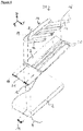
- FIG 4 shows a further form of embodiment of a covering device 30 belonging to the invention, in an exploded representation.
- the rib structure 11 of the covering device 30 comprises ribs 12, the first ends 18 of which are connected to one another by a transverse element of said rib structure.
- the ribs are disposed parallel to, and equidistantly from, one another and extend in the xy plane.
- the transverse element 19 of the rib structure likewise extends in the xy plane, but perpendicularly to the longitudinal direction of the ribs 12.
- the sealing element 8 rectilinear reinforcing elements 20, the stiffness of which is greater than that of said sealing element 8 and which are disposed in such a way that bending of the reinforcing elements within the xz plane is prevented or at least made difficult.
- the reinforcing elements 20 may be "displaced"/curled downwards (the z-direction) as a whole like a roller shutter, while retaining their rectilinear shape.
- the provision of the reinforcing elements 20 has the advantage that these form a grid, together with the ribs 12, which makes it additionally difficult to penetrate the covering device 30. Nevertheless, the sealing element 8 can be satisfactorily deflected/curled downwards (the z direction).
- the second ends 16 terminate flush with one edge 22 of an outer reinforcing element 20, but this is not a requirement.
- the rib structure 11 is mounted, together with the sealing element 8, on the first component 2 (for example a panel) by means of bonding or screwing within the area 14.
- first component 2 for example a panel
- second component 3 in a first stage (slight relative movement) only that area of the sealing element 8 which is identified by the reference numeral 15 is deflected/curled downwards (the z direction), under which circumstances the ribs 12 belonging to the rib structure 11 do not bend.
- a second stage that part of the sealing element 8 which is identified by the reference numeral 21 is additionally deflected/curled downwards (in the z direction), and at the same time the ribs 12 are bent in the xy plane, i.e. the second ends 16 are moved within the xy plane, but the first ends 18 of the ribs 12 are securely fixed in position with respect to the xy direction.
Landscapes
- Engineering & Computer Science (AREA)
- Aviation & Aerospace Engineering (AREA)
- Mechanical Engineering (AREA)
- General Engineering & Computer Science (AREA)
- Physics & Mathematics (AREA)
- Geometry (AREA)
- Gasket Seals (AREA)
- Sealing Devices (AREA)
Claims (11)
- Dispositif de recouvrement (10, 30) pour recouvrir un espace (4) entre un premier composant (2) et un second composant (3) dans un avion comprenant :- un élément d'étanchéité (8) conçu pour être fixé au premier composant (2) dans une zone (14) ; et- une structure nervurée (11) qui est disposée sur une surface de l'élément d'étanchéité (8), la structure nervurée (11) comprenant une pluralité de nervures (12) qui s'étendent parallèlement à la surface de l'élément d'étanchéité (8), la flexibilité des nervures (12) parallèles à la surface de l'élément d'étanchéité (8) étant élevée, et la flexibilité des nervuresperpendiculaires à la surface de l'élément d'étanchéité (8) étant faible, et la structure nervurée (11) étant conçue pour être montée, avec l'élément d'étanchéité (8), sur le premier composant (2) dans la zone (14) par collage ou vissage.
- Dispositif de recouvrement (10, 30) selon la revendication 1,
au moins certaines des nervures (12) s'étendant parallèlement les unes aux autres. - Dispositif de recouvrement (10, 30) selon la revendication 1 ou 2,
les premières extrémités (18) des nervures (12) étant chacune reliées à un élément transversal (19) de la structure nervurée de sorte que ladite structure nervurée (11) ait, dans son ensemble, une formation en forme de peigne. - Dispositif de recouvrement (10, 30) selon l'une des revendications 1 à 3, l'élément d'étanchéité (8) comprenant un film plastique ou un matelas plastique ou comprenant des zones de film plastique.
- Dispositif de recouvrement (10, 30) selon l'une des revendications 1 à 4,
une partie (15) de l'élément d'étanchéité (8) faisant saillie au-delà des secondes extrémités (16) des nervures (12). - Dispositif de recouvrement (10, 30) selon la revendication 5,
la partie (15) de l'élément d'étanchéité (8) qui fait saillie au-delà des secondes extrémités (16) des nervures (12) étant flexible perpendiculairement à la surface de la partie restante de l'élément d'étanchéité. - Dispositif de recouvrement (10, 30) selon la revendication 5 ou 6,
l'élément d'étanchéité (8) dépassant d'environ 1 cm des secondes extrémités (16) des nervures (12). - Dispositif de recouvrement (10, 30) selon l'une des revendications 1 à 7,
des éléments de renforcement (20), dont la rigidité est supérieure à celle dudit élément d'étanchéité (8) et qui sont disposés de sorte que la flexion de l'élément d'étanchéité (8) perpendiculairement à la surface dudit élément d'étanchéité (8) soit rendue difficile, étant disposés dans ou sur l'élément d'étanchéité (8). - Zone d'avion comprenant :- un premier composant (2) ;- un second composant (3) qui est séparé du premier composant (2) par un espace (4) ; et- un dispositif de recouvrement (20, 30) selon l'une des revendications 1 à 8, ledit dispositif de recouvrement (20, 30) étant disposé au niveau de l'espace (4) entre le premier composant (2) et le second composant (3) de sorte qu'il recouvre au moins partiellement ledit espace (4), et la structure nervurée (11) du dispositif de recouvrement (20, 30) étant montée, avec l'élément d'étanchéité (8) du dispositif de recouvrement (20, 30), sur le premier composant (2) dans la zone (14) par collage ou vissage.
- Zone d'avion selon la revendication 9,
le premier composant (2) étant un panneau, et le second composant (3) étant un repère. - Zone d'avion selon la revendication 9 ou 10,
les nervures (12) de la structure nervurée (11) s'étendent le long de lignes droites qui coupent au moins un bord, de bords opposés (13) de l'espace (4) qui s'étendent parallèlement les uns aux autres, à un angle (α) qui n'est pas égal à 90°.
Applications Claiming Priority (2)
| Application Number | Priority Date | Filing Date | Title |
|---|---|---|---|
| US201161568669P | 2011-12-09 | 2011-12-09 | |
| DE102011120762A DE102011120762A1 (de) | 2011-12-09 | 2011-12-09 | Abdeckungsvorrichtung sowie Flugzeugbereich mit Abdeckungsvorrichtung |
Publications (3)
| Publication Number | Publication Date |
|---|---|
| EP2602188A2 EP2602188A2 (fr) | 2013-06-12 |
| EP2602188A3 EP2602188A3 (fr) | 2016-02-17 |
| EP2602188B1 true EP2602188B1 (fr) | 2019-07-31 |
Family
ID=47602861
Family Applications (1)
| Application Number | Title | Priority Date | Filing Date |
|---|---|---|---|
| EP12195907.6A Active EP2602188B1 (fr) | 2011-12-09 | 2012-12-06 | Dispositif de recouvrement et zone d'avion comprenant un dispositif de recouvrement |
Country Status (3)
| Country | Link |
|---|---|
| US (1) | US8882045B2 (fr) |
| EP (1) | EP2602188B1 (fr) |
| DE (1) | DE102011120762A1 (fr) |
Families Citing this family (12)
| Publication number | Priority date | Publication date | Assignee | Title |
|---|---|---|---|---|
| GB201008863D0 (en) * | 2010-05-27 | 2010-07-14 | Airbus Operations Ltd | Method of sealing a gap |
| CA3192310A1 (fr) | 2014-04-25 | 2015-10-29 | Bombardier Inc. | Zone tampon pour des elements interieurs d'aeronef |
| US10017239B2 (en) | 2015-12-18 | 2018-07-10 | Northrop Grumman Systems Corporation | Dynamic conformal aerodynamic seal (CAS) for aircraft control surfaces |
| US9944379B2 (en) | 2016-09-06 | 2018-04-17 | The Boeing Company | Moisture path close-out and thermal control system and methods of assembling same |
| GB2555861A (en) * | 2016-11-15 | 2018-05-16 | Airbus Operations Ltd | Aircraft gap seal |
| US11072411B2 (en) | 2017-10-11 | 2021-07-27 | The Boeing Company | Devices and methods for diverting moisture from a support member |
| DE102017125299A1 (de) * | 2017-10-27 | 2019-05-02 | Airbus Operations Gmbh | Spaltabdeckung zwischen Kabinenmonumenten, insbesondere für eine Passagierkabine eines Flugzeuges |
| US10793248B2 (en) | 2017-10-30 | 2020-10-06 | The Boeing Company | Devices and methods to capture moisture from a structural member |
| DE102019119558A1 (de) * | 2019-07-18 | 2021-01-21 | Recaro Aircraft Seating Gmbh & Co. Kg | Dichtungsvorrichtung |
| US11320296B2 (en) | 2020-03-30 | 2022-05-03 | The Boeing Company | Test cage for testing a gap in a vehicle |
| DE102024113038A1 (de) * | 2024-05-08 | 2025-11-13 | Airbus Operations Gmbh | Dichtungs- und Halteelement für ein Luftfahrzeug |
| DE102024126405A1 (de) * | 2024-09-13 | 2026-03-19 | Airbus Operations Gmbh | Anordnung von Verkleidungselementen einer Flugzeugkabine, Verkleidungselement, Spaltabdeckung und Installationsverfahren |
Family Cites Families (12)
| Publication number | Priority date | Publication date | Assignee | Title |
|---|---|---|---|---|
| US5014934A (en) * | 1989-06-30 | 1991-05-14 | The Boeing Company | Removable seal for discontinuities in aircraft skin |
| DE9200494U1 (de) * | 1992-01-17 | 1992-03-12 | Deutsche Airbus GmbH, 2000 Hamburg | Dichtprofil für Verkleidungsteile |
| US5269624A (en) | 1992-04-30 | 1993-12-14 | Tremco, Inc. | Expansion joint system |
| US5365713A (en) * | 1992-12-14 | 1994-11-22 | Pawling Corporation | Elastomeric seismic seal system |
| US5827598A (en) * | 1996-11-05 | 1998-10-27 | The Boeing Company | Method and apparatus for sealing an aircraft penetration |
| DE102004049893B4 (de) | 2004-10-13 | 2010-07-01 | Airbus Deutschland Gmbh | Fugenabdeckung in Flugzeugen |
| EP1647480B1 (fr) | 2004-10-13 | 2010-12-08 | Airbus Operations GmbH | Couvre-joint pour aéronefs |
| DE102006017241B4 (de) * | 2006-04-12 | 2017-11-23 | Airbus Operations Gmbh | Ebene Spaltabdeckung für Kabinenverkleidungen |
| FR2905748B1 (fr) * | 2006-09-08 | 2011-04-15 | Airbus France | Assemblage de panneaux et procede de fabrication |
| US8052152B2 (en) * | 2007-03-09 | 2011-11-08 | Federal-Mogul Corporation | Dynamic shaft seal and method of installation thereof |
| DE102007013904A1 (de) | 2007-03-22 | 2008-09-25 | Airbus Deutschland Gmbh | Spaltabdeckvorrichtung |
| US8439597B2 (en) * | 2011-10-05 | 2013-05-14 | Richard Diamond | Asphalt paving seam sealer system |
-
2011
- 2011-12-09 DE DE102011120762A patent/DE102011120762A1/de not_active Ceased
-
2012
- 2012-12-06 EP EP12195907.6A patent/EP2602188B1/fr active Active
- 2012-12-07 US US13/708,282 patent/US8882045B2/en active Active
Non-Patent Citations (1)
| Title |
|---|
| None * |
Also Published As
| Publication number | Publication date |
|---|---|
| EP2602188A2 (fr) | 2013-06-12 |
| EP2602188A3 (fr) | 2016-02-17 |
| US8882045B2 (en) | 2014-11-11 |
| US20130168496A1 (en) | 2013-07-04 |
| DE102011120762A1 (de) | 2013-06-13 |
Similar Documents
| Publication | Publication Date | Title |
|---|---|---|
| EP2602188B1 (fr) | Dispositif de recouvrement et zone d'avion comprenant un dispositif de recouvrement | |
| ES2910461T3 (es) | Combinación de una superficie aerodinámica y un arreglos de dentículos | |
| EP1991803B1 (fr) | Hublot d'aéronef | |
| US8882049B2 (en) | Airfoil system for cruising flight | |
| EP2070816B1 (fr) | Procédés et appareil pour panneau aérodynamique intégré | |
| US10017239B2 (en) | Dynamic conformal aerodynamic seal (CAS) for aircraft control surfaces | |
| US9221411B2 (en) | Gasbag for a personal protection device | |
| EP3103727B1 (fr) | Panneau à distance d'un système de protection thermique et son procédé de fabrication | |
| JP7250497B2 (ja) | 航空機の複合材パネルのコア構造、コア構造を含む複合材パネルと航空機、及び複合材パネルの製造方法 | |
| EP2662284A2 (fr) | Protection contre le givrage pour aéronef à l'aide de surfaces de polymère électroactif | |
| WO2010070185A3 (fr) | Bord de fuite de surface stabilisatrice d'un aéronef | |
| WO2008076283A3 (fr) | Structure alvéolaire | |
| EP2907744A1 (fr) | Ensemble de montage de pare-brise | |
| EP2862798A2 (fr) | Structure d'aéronef et procédé de fabrication | |
| WO2011010155A3 (fr) | Direction de véhicules par commande de profils aérodynamiques | |
| KR20130033442A (ko) | 차량 내장용 트림 부품, 특히 내측 도어 라이닝 | |
| US20180015651A1 (en) | Profiled section, especially for a motor vehicle, and method for the production thereof | |
| WO2012080217A3 (fr) | Agencement de fixation et raccord de fixation pour fixer un composant à un composant structural d'un aéronef ou d'un vaisseau spatial | |
| US20050238482A1 (en) | Segmented rotor blade trim tab | |
| EP1963095B1 (fr) | Dispositif de protection | |
| US10906631B2 (en) | Lifting surface | |
| EP1857359A2 (fr) | Système de fermeture pour l'espace existant entre le fuselage et la gouverne horizontale d'un avion avec stabilisateur horizontal orientable | |
| SE514143C2 (sv) | Golvpanel för ett fordonsgolv | |
| CN103596840A (zh) | 用于覆盖在飞行器的两个结构部之间的缝隙的双曲覆盖件 | |
| CN106660627A (zh) | 内部飞机特征的缓冲区 |
Legal Events
| Date | Code | Title | Description |
|---|---|---|---|
| PUAI | Public reference made under article 153(3) epc to a published international application that has entered the european phase |
Free format text: ORIGINAL CODE: 0009012 |
|
| 17P | Request for examination filed |
Effective date: 20121206 |
|
| AK | Designated contracting states |
Kind code of ref document: A2 Designated state(s): AL AT BE BG CH CY CZ DE DK EE ES FI FR GB GR HR HU IE IS IT LI LT LU LV MC MK MT NL NO PL PT RO RS SE SI SK SM TR |
|
| AX | Request for extension of the european patent |
Extension state: BA ME |
|
| PUAL | Search report despatched |
Free format text: ORIGINAL CODE: 0009013 |
|
| AK | Designated contracting states |
Kind code of ref document: A3 Designated state(s): AL AT BE BG CH CY CZ DE DK EE ES FI FR GB GR HR HU IE IS IT LI LT LU LV MC MK MT NL NO PL PT RO RS SE SI SK SM TR |
|
| AX | Request for extension of the european patent |
Extension state: BA ME |
|
| RIC1 | Information provided on ipc code assigned before grant |
Ipc: B64D 11/04 20060101AFI20160111BHEP Ipc: F16J 15/32 20060101ALI20160111BHEP Ipc: B65D 65/02 20060101ALI20160111BHEP Ipc: E06B 1/64 20060101ALI20160111BHEP |
|
| GRAP | Despatch of communication of intention to grant a patent |
Free format text: ORIGINAL CODE: EPIDOSNIGR1 |
|
| STAA | Information on the status of an ep patent application or granted ep patent |
Free format text: STATUS: GRANT OF PATENT IS INTENDED |
|
| INTG | Intention to grant announced |
Effective date: 20190326 |
|
| GRAS | Grant fee paid |
Free format text: ORIGINAL CODE: EPIDOSNIGR3 |
|
| GRAA | (expected) grant |
Free format text: ORIGINAL CODE: 0009210 |
|
| STAA | Information on the status of an ep patent application or granted ep patent |
Free format text: STATUS: THE PATENT HAS BEEN GRANTED |
|
| AK | Designated contracting states |
Kind code of ref document: B1 Designated state(s): AL AT BE BG CH CY CZ DE DK EE ES FI FR GB GR HR HU IE IS IT LI LT LU LV MC MK MT NL NO PL PT RO RS SE SI SK SM TR |
|
| REG | Reference to a national code |
Ref country code: CH Ref legal event code: EP Ref country code: GB Ref legal event code: FG4D |
|
| REG | Reference to a national code |
Ref country code: AT Ref legal event code: REF Ref document number: 1160619 Country of ref document: AT Kind code of ref document: T Effective date: 20190815 |
|
| REG | Reference to a national code |
Ref country code: IE Ref legal event code: FG4D |
|
| REG | Reference to a national code |
Ref country code: DE Ref legal event code: R096 Ref document number: 602012062414 Country of ref document: DE |
|
| REG | Reference to a national code |
Ref country code: NL Ref legal event code: MP Effective date: 20190731 |
|
| REG | Reference to a national code |
Ref country code: LT Ref legal event code: MG4D |
|
| REG | Reference to a national code |
Ref country code: AT Ref legal event code: MK05 Ref document number: 1160619 Country of ref document: AT Kind code of ref document: T Effective date: 20190731 |
|
| PG25 | Lapsed in a contracting state [announced via postgrant information from national office to epo] |
Ref country code: FI Free format text: LAPSE BECAUSE OF FAILURE TO SUBMIT A TRANSLATION OF THE DESCRIPTION OR TO PAY THE FEE WITHIN THE PRESCRIBED TIME-LIMIT Effective date: 20190731 Ref country code: PT Free format text: LAPSE BECAUSE OF FAILURE TO SUBMIT A TRANSLATION OF THE DESCRIPTION OR TO PAY THE FEE WITHIN THE PRESCRIBED TIME-LIMIT Effective date: 20191202 Ref country code: SE Free format text: LAPSE BECAUSE OF FAILURE TO SUBMIT A TRANSLATION OF THE DESCRIPTION OR TO PAY THE FEE WITHIN THE PRESCRIBED TIME-LIMIT Effective date: 20190731 Ref country code: AT Free format text: LAPSE BECAUSE OF FAILURE TO SUBMIT A TRANSLATION OF THE DESCRIPTION OR TO PAY THE FEE WITHIN THE PRESCRIBED TIME-LIMIT Effective date: 20190731 Ref country code: NL Free format text: LAPSE BECAUSE OF FAILURE TO SUBMIT A TRANSLATION OF THE DESCRIPTION OR TO PAY THE FEE WITHIN THE PRESCRIBED TIME-LIMIT Effective date: 20190731 Ref country code: BG Free format text: LAPSE BECAUSE OF FAILURE TO SUBMIT A TRANSLATION OF THE DESCRIPTION OR TO PAY THE FEE WITHIN THE PRESCRIBED TIME-LIMIT Effective date: 20191031 Ref country code: NO Free format text: LAPSE BECAUSE OF FAILURE TO SUBMIT A TRANSLATION OF THE DESCRIPTION OR TO PAY THE FEE WITHIN THE PRESCRIBED TIME-LIMIT Effective date: 20191031 Ref country code: LT Free format text: LAPSE BECAUSE OF FAILURE TO SUBMIT A TRANSLATION OF THE DESCRIPTION OR TO PAY THE FEE WITHIN THE PRESCRIBED TIME-LIMIT Effective date: 20190731 Ref country code: HR Free format text: LAPSE BECAUSE OF FAILURE TO SUBMIT A TRANSLATION OF THE DESCRIPTION OR TO PAY THE FEE WITHIN THE PRESCRIBED TIME-LIMIT Effective date: 20190731 |
|
| PG25 | Lapsed in a contracting state [announced via postgrant information from national office to epo] |
Ref country code: IS Free format text: LAPSE BECAUSE OF FAILURE TO SUBMIT A TRANSLATION OF THE DESCRIPTION OR TO PAY THE FEE WITHIN THE PRESCRIBED TIME-LIMIT Effective date: 20191130 Ref country code: RS Free format text: LAPSE BECAUSE OF FAILURE TO SUBMIT A TRANSLATION OF THE DESCRIPTION OR TO PAY THE FEE WITHIN THE PRESCRIBED TIME-LIMIT Effective date: 20190731 Ref country code: AL Free format text: LAPSE BECAUSE OF FAILURE TO SUBMIT A TRANSLATION OF THE DESCRIPTION OR TO PAY THE FEE WITHIN THE PRESCRIBED TIME-LIMIT Effective date: 20190731 Ref country code: LV Free format text: LAPSE BECAUSE OF FAILURE TO SUBMIT A TRANSLATION OF THE DESCRIPTION OR TO PAY THE FEE WITHIN THE PRESCRIBED TIME-LIMIT Effective date: 20190731 Ref country code: GR Free format text: LAPSE BECAUSE OF FAILURE TO SUBMIT A TRANSLATION OF THE DESCRIPTION OR TO PAY THE FEE WITHIN THE PRESCRIBED TIME-LIMIT Effective date: 20191101 Ref country code: ES Free format text: LAPSE BECAUSE OF FAILURE TO SUBMIT A TRANSLATION OF THE DESCRIPTION OR TO PAY THE FEE WITHIN THE PRESCRIBED TIME-LIMIT Effective date: 20190731 |
|
| PG25 | Lapsed in a contracting state [announced via postgrant information from national office to epo] |
Ref country code: TR Free format text: LAPSE BECAUSE OF FAILURE TO SUBMIT A TRANSLATION OF THE DESCRIPTION OR TO PAY THE FEE WITHIN THE PRESCRIBED TIME-LIMIT Effective date: 20190731 |
|
| PG25 | Lapsed in a contracting state [announced via postgrant information from national office to epo] |
Ref country code: IT Free format text: LAPSE BECAUSE OF FAILURE TO SUBMIT A TRANSLATION OF THE DESCRIPTION OR TO PAY THE FEE WITHIN THE PRESCRIBED TIME-LIMIT Effective date: 20190731 Ref country code: PL Free format text: LAPSE BECAUSE OF FAILURE TO SUBMIT A TRANSLATION OF THE DESCRIPTION OR TO PAY THE FEE WITHIN THE PRESCRIBED TIME-LIMIT Effective date: 20190731 Ref country code: EE Free format text: LAPSE BECAUSE OF FAILURE TO SUBMIT A TRANSLATION OF THE DESCRIPTION OR TO PAY THE FEE WITHIN THE PRESCRIBED TIME-LIMIT Effective date: 20190731 Ref country code: DK Free format text: LAPSE BECAUSE OF FAILURE TO SUBMIT A TRANSLATION OF THE DESCRIPTION OR TO PAY THE FEE WITHIN THE PRESCRIBED TIME-LIMIT Effective date: 20190731 Ref country code: RO Free format text: LAPSE BECAUSE OF FAILURE TO SUBMIT A TRANSLATION OF THE DESCRIPTION OR TO PAY THE FEE WITHIN THE PRESCRIBED TIME-LIMIT Effective date: 20190731 |
|
| PGFP | Annual fee paid to national office [announced via postgrant information from national office to epo] |
Ref country code: GB Payment date: 20191220 Year of fee payment: 8 |
|
| PG25 | Lapsed in a contracting state [announced via postgrant information from national office to epo] |
Ref country code: CZ Free format text: LAPSE BECAUSE OF FAILURE TO SUBMIT A TRANSLATION OF THE DESCRIPTION OR TO PAY THE FEE WITHIN THE PRESCRIBED TIME-LIMIT Effective date: 20190731 Ref country code: SK Free format text: LAPSE BECAUSE OF FAILURE TO SUBMIT A TRANSLATION OF THE DESCRIPTION OR TO PAY THE FEE WITHIN THE PRESCRIBED TIME-LIMIT Effective date: 20190731 Ref country code: IS Free format text: LAPSE BECAUSE OF FAILURE TO SUBMIT A TRANSLATION OF THE DESCRIPTION OR TO PAY THE FEE WITHIN THE PRESCRIBED TIME-LIMIT Effective date: 20200224 Ref country code: SM Free format text: LAPSE BECAUSE OF FAILURE TO SUBMIT A TRANSLATION OF THE DESCRIPTION OR TO PAY THE FEE WITHIN THE PRESCRIBED TIME-LIMIT Effective date: 20190731 |
|
| REG | Reference to a national code |
Ref country code: DE Ref legal event code: R097 Ref document number: 602012062414 Country of ref document: DE |
|
| PLBE | No opposition filed within time limit |
Free format text: ORIGINAL CODE: 0009261 |
|
| STAA | Information on the status of an ep patent application or granted ep patent |
Free format text: STATUS: NO OPPOSITION FILED WITHIN TIME LIMIT |
|
| PG2D | Information on lapse in contracting state deleted |
Ref country code: IS |
|
| PG25 | Lapsed in a contracting state [announced via postgrant information from national office to epo] |
Ref country code: IS Free format text: LAPSE BECAUSE OF FAILURE TO SUBMIT A TRANSLATION OF THE DESCRIPTION OR TO PAY THE FEE WITHIN THE PRESCRIBED TIME-LIMIT Effective date: 20191030 |
|
| REG | Reference to a national code |
Ref country code: CH Ref legal event code: PL |
|
| 26N | No opposition filed |
Effective date: 20200603 |
|
| REG | Reference to a national code |
Ref country code: BE Ref legal event code: MM Effective date: 20191231 |
|
| PG25 | Lapsed in a contracting state [announced via postgrant information from national office to epo] |
Ref country code: SI Free format text: LAPSE BECAUSE OF FAILURE TO SUBMIT A TRANSLATION OF THE DESCRIPTION OR TO PAY THE FEE WITHIN THE PRESCRIBED TIME-LIMIT Effective date: 20190731 Ref country code: MC Free format text: LAPSE BECAUSE OF FAILURE TO SUBMIT A TRANSLATION OF THE DESCRIPTION OR TO PAY THE FEE WITHIN THE PRESCRIBED TIME-LIMIT Effective date: 20190731 |
|
| PG25 | Lapsed in a contracting state [announced via postgrant information from national office to epo] |
Ref country code: IE Free format text: LAPSE BECAUSE OF NON-PAYMENT OF DUE FEES Effective date: 20191206 Ref country code: LU Free format text: LAPSE BECAUSE OF NON-PAYMENT OF DUE FEES Effective date: 20191206 |
|
| PG25 | Lapsed in a contracting state [announced via postgrant information from national office to epo] |
Ref country code: LI Free format text: LAPSE BECAUSE OF NON-PAYMENT OF DUE FEES Effective date: 20191231 Ref country code: CH Free format text: LAPSE BECAUSE OF NON-PAYMENT OF DUE FEES Effective date: 20191231 Ref country code: BE Free format text: LAPSE BECAUSE OF NON-PAYMENT OF DUE FEES Effective date: 20191231 |
|
| PG25 | Lapsed in a contracting state [announced via postgrant information from national office to epo] |
Ref country code: CY Free format text: LAPSE BECAUSE OF FAILURE TO SUBMIT A TRANSLATION OF THE DESCRIPTION OR TO PAY THE FEE WITHIN THE PRESCRIBED TIME-LIMIT Effective date: 20190731 |
|
| PG25 | Lapsed in a contracting state [announced via postgrant information from national office to epo] |
Ref country code: MT Free format text: LAPSE BECAUSE OF FAILURE TO SUBMIT A TRANSLATION OF THE DESCRIPTION OR TO PAY THE FEE WITHIN THE PRESCRIBED TIME-LIMIT Effective date: 20190731 Ref country code: HU Free format text: LAPSE BECAUSE OF FAILURE TO SUBMIT A TRANSLATION OF THE DESCRIPTION OR TO PAY THE FEE WITHIN THE PRESCRIBED TIME-LIMIT; INVALID AB INITIO Effective date: 20121206 |
|
| GBPC | Gb: european patent ceased through non-payment of renewal fee |
Effective date: 20201206 |
|
| PG25 | Lapsed in a contracting state [announced via postgrant information from national office to epo] |
Ref country code: GB Free format text: LAPSE BECAUSE OF NON-PAYMENT OF DUE FEES Effective date: 20201206 |
|
| PGFP | Annual fee paid to national office [announced via postgrant information from national office to epo] |
Ref country code: FR Payment date: 20211224 Year of fee payment: 10 |
|
| PG25 | Lapsed in a contracting state [announced via postgrant information from national office to epo] |
Ref country code: MK Free format text: LAPSE BECAUSE OF FAILURE TO SUBMIT A TRANSLATION OF THE DESCRIPTION OR TO PAY THE FEE WITHIN THE PRESCRIBED TIME-LIMIT Effective date: 20190731 |
|
| PG25 | Lapsed in a contracting state [announced via postgrant information from national office to epo] |
Ref country code: FR Free format text: LAPSE BECAUSE OF NON-PAYMENT OF DUE FEES Effective date: 20221231 |
|
| PGFP | Annual fee paid to national office [announced via postgrant information from national office to epo] |
Ref country code: DE Payment date: 20241210 Year of fee payment: 13 |