EP2602190A2 - Dispositif de fixation - Google Patents
Dispositif de fixation Download PDFInfo
- Publication number
- EP2602190A2 EP2602190A2 EP20120008175 EP12008175A EP2602190A2 EP 2602190 A2 EP2602190 A2 EP 2602190A2 EP 20120008175 EP20120008175 EP 20120008175 EP 12008175 A EP12008175 A EP 12008175A EP 2602190 A2 EP2602190 A2 EP 2602190A2
- Authority
- EP
- European Patent Office
- Prior art keywords
- locking
- hole
- rail
- fastening device
- base body
- Prior art date
- Legal status (The legal status is an assumption and is not a legal conclusion. Google has not performed a legal analysis and makes no representation as to the accuracy of the status listed.)
- Withdrawn
Links
Images

Classifications
-
- B—PERFORMING OPERATIONS; TRANSPORTING
- B60—VEHICLES IN GENERAL
- B60N—SEATS SPECIALLY ADAPTED FOR VEHICLES; VEHICLE PASSENGER ACCOMMODATION NOT OTHERWISE PROVIDED FOR
- B60N2/00—Seats specially adapted for vehicles; Arrangement or mounting of seats in vehicles
- B60N2/005—Arrangement or mounting of seats in vehicles, e.g. dismountable auxiliary seats
- B60N2/015—Attaching seats directly to vehicle chassis
- B60N2/01508—Attaching seats directly to vehicle chassis using quick release attachments
- B60N2/01516—Attaching seats directly to vehicle chassis using quick release attachments with locking mechanisms
- B60N2/01558—Attaching seats directly to vehicle chassis using quick release attachments with locking mechanisms with key and slot
- B60N2/01575—Attaching seats directly to vehicle chassis using quick release attachments with locking mechanisms with key and slot key sliding inside the vehicle floor or rail
-
- B—PERFORMING OPERATIONS; TRANSPORTING
- B60—VEHICLES IN GENERAL
- B60N—SEATS SPECIALLY ADAPTED FOR VEHICLES; VEHICLE PASSENGER ACCOMMODATION NOT OTHERWISE PROVIDED FOR
- B60N2/00—Seats specially adapted for vehicles; Arrangement or mounting of seats in vehicles
- B60N2/24—Seats specially adapted for vehicles; Arrangement or mounting of seats in vehicles for particular purposes or particular vehicles
- B60N2/242—Bus seats
-
- B—PERFORMING OPERATIONS; TRANSPORTING
- B64—AIRCRAFT; AVIATION; COSMONAUTICS
- B64D—EQUIPMENT FOR FITTING IN OR TO AIRCRAFT; FLIGHT SUITS; PARACHUTES; ARRANGEMENT OR MOUNTING OF POWER PLANTS OR PROPULSION TRANSMISSIONS IN AIRCRAFT
- B64D11/00—Passenger or crew accommodation; Flight-deck installations not otherwise provided for
- B64D11/06—Arrangements of seats, or adaptations or details specially adapted for aircraft seats
- B64D11/0696—Means for fastening seats to floors, e.g. to floor rails
Definitions
- the present invention relates to a fastening device for fastening a seat or other vehicle equipment component to a hole-latching rail, comprising a can be placed on the hole-latching rail body, at least one of the main body in the longitudinal direction of the hole-latch rail between two end positions slidably guided, at least one mushroom-shaped, for engagement in the undercuts of the hole-locking rail certain locking element having locking body which is displaceable relative to the base body by means of an operating element, and at least one of the main body transversely to the longitudinal direction of the hole-locking rail slidably guided Locking element, which is movable between an engaging in the hole-locking rail lowered and a non-engaging in the hole-locking rail raised position, wherein in the first end position of the sliding movement of the locking body, the locking element between two projections the hole-locking rail engages in the undercuts.
- Fastening devices which serve the attachment of seats and other interior components in aircraft or other vehicles to standardized mounting rails (so-called "snap-hole rails") are known in various embodiments and in use. So is from the European patent specification EP-B-0583295 a fastening device with the features shown at the beginning for the attachment of aviation interior designs known on mounting rails.
- These Fastening device comprises, as set forth on the hole-locking rail (in particular over a large area on standing or clamping surfaces) attachable base body to which typically the interior component to be fastened may be attached and is assigned to the longitudinal locking of the fastening device in the mounting rail a locking element, and a slidable latch body having mushroom-shaped latch members for engaging in undercuts of the mounting rail.
- the locking element can either as a rigid connected to the body or as a - coupled via mechanical transmission means with the movement of the locking body - movable, namely in the sense of the above-described design axially (up and down) movable or rotatable about its longitudinal axis locking pin be designed.
- the embodiments with non-rigid locking element have the particular advantage that the respective fastening device - can be moved resting on the mounting rail - at a corresponding "unlatched" position of the locking element, which is not possible in a rigidly connected to the main body locking element.
- the fastening device must be lifted off the fastening rail.
- the locking body is displaceable by means of an actuating lever in the longitudinal direction of the base body.
- guide grooves are provided for this purpose. These close with formed on the body, intended to rest on the hole-locking rail clamping surfaces a small angle. In a displacement of the locking body in the direction of a locking position thereby reduces the distance between the Locking element and the clamping surfaces, whereby a clamped locking position ("anti-rattle" compound) is made. In this position, this fastening device provides a backlash-free and secured against rattling connection between the mounting rail and the fastening device.
- the DE-A-102008048745 shows a locking device for a lockable on a rail object, in which a locking body is mounted movable up and down on a base body.
- a mounted in the longitudinal direction of the mounting rail on the base body and connected to the locking body actuating element has three scenes, in which pins are guided, which are connected to the locking body or a submersible body.
- the actuator By moving a lever in the longitudinal direction of the rail, the actuator also move in the same direction and thus the pins in the scenes.
- the resulting link guide causes a lifting of the locking body or a lowering of the immersion body and vice versa.
- the movements of the locking body and the immersion body are coupled together and by actuating the actuating element, the locking device can be locked or released.
- this object is achieved in that the movement of the at least one latching element and the movement of the at least one latch body relative to the base body are not coupled together and the detent element are associated with a spring device and a separate actuator, in particular an actuating lever such a case in a fixing device set forth above, that the locking element by Actuating the actuating element against the biasing force of the spring device in its not engaging in the hole-locking rail position raised and biased when not actuated actuator by means of the spring means relative to the base body in its lowered, engaging in the hole-latch rail position, wherein further when the locking body assumes its first end position, a first blocking element of the locking body or a component coupled thereto engages in such a way in a second locking element of the locking element or a coupled thereto component that the locking element is fixed in its biased by the spring means lowered position.
- the engaging in the hole-locking rail lowered position of the locking element is hereinafter referred to as "normal position", which does not engage in the hole-locking rail raised position with “displacement position”.
- the locking body is in its first end position in the "locking position” and in its opposite end position in the "assembly position”.
- the attachable to the hole-latching rail body has mounting options for example. Seats or other vehicle equipment components. These mounting options can be realized for example by pendulum or other bearings, eyes, bolts or screws.
- the operating and the operating lever are preferably via mechanical transmission means (tooth pairings such as gear / rack, leverage, eccentric or the like.)
- the operating lever for the locking body is movable in one possible embodiment between two end positions. His first end position herein corresponds to the locking position of the latch body, its second its mounting position.
- the actuating lever for the locking element is also movable between two end positions in a possible embodiment. His first end position corresponds herein to the normal position of the locking element, its second its displacement position.
- the actuating lever is preferred but not mandatory (see below) to bring into its normal position of the locking element corresponding position.
- the locking elements and the locking element are in the corresponding recesses of the hole-locking rail bring, and then the operating lever is to be pivoted in its the locking position of the locking body corresponding position.
- the base body is fixed to the hole-latching rail in the longitudinal direction and both transverse directions.
- the locking element is secured by the interaction of the first and second locking element against unwanted release from the normal position by the locking body is directly or indirectly connected to the locking element that possible on the locking element axially acting forces, for example, by vibrations, shocks or other shocks may occur, is counteracted and the locking element is held securely in this manner in its axial direction of movement.
- a nose or other projection of the locking body in its locking position on a corresponding mating surface eg a depression or recess, a collar, a shoulder or an end face
- the invention thus makes a significant contribution to meeting ever-increasing safety test requirements for aerospace components, in which the fasteners are subjected, inter alia, a multiple of gravitational acceleration (16 G) and thereby neither material damage nor may be released from its fastened position.
- the locking element when the locking body is not in its first end position (“locking position"), can be raised against the biasing force of the spring device, placing the fastening device without the locking element exactly with a recess of the hole-locking Rail is aligned, just as little damage to the Mounting rail lead as the attempt to fix the fastening device in such a position - by turning the operating lever in its non-actuated position -. Also, this forms after a damage to the mounting rail is a potential security risk, a significant safety aspect.
- the fastening device is already attached to the hole-latching rail, i. put on this, so can be a shift in the longitudinal direction (by a hole pitch, which is usually one inch, or more of these pitch pitches), as follows:
- the fastening device To move to a hole pitch, at least if the fastening device is designed in anti-rattle design, the operating lever in its the mounting position of the latch body corresponding second position and the operating lever in its the displacement position of the locking element corresponding position to bring. Subsequently, the fastening device is slightly, for example, by about half a hole pitch to move in the desired direction in an intermediate position. Then, the actuating lever can be moved back to its normal position of the locking element corresponding position, whereby the spring means presses the lower surface of the locking element on the underlying areas of the projections of the hole-locking rail. The locking element engages in the next hole pitch, as soon as this is achieved by further displacement of the fastening device in the longitudinal direction of the hole-locking rail.
- the operating lever is in his the locking position of the locking body corresponding To pivot position, and the main body is fixed to the hole-latching rail in the longitudinal direction (x-direction), in the transverse direction (y-direction) and in the vertical direction (z-direction). Accordingly, to proceed when the patch on the hole-locking rail fastening device to be moved by more than one hole pitch, in which case the intermediate position of the fastening device, in which the actuating lever is pivoted back into its normal position of the locking element corresponding position, for example a half hole pitch away from the desired end position.
- the fastening device can in principle also be placed on the hole-latching rail when the latching element is raised. Since in the mounting position of the latch body, the locking elements are typically exactly one inch or a multiple thereof away from the locking element, usually comes when placing the fastening device on the hole-locking rail even with raised locking element this right to lie over a recess.
- the illustrated decoupling of the operating and the actuating element or the locking body and the locking element facilitates, as can be seen from the above explanation without further, in conjunction with the spring-guided locking element the correct and secure attachment or moving and securing the fastening device and thus the seats or other vehicle equipment components on the snap-lock rail, by the operator through an acoustic perceivable and / or haptic noticeable signal of the latch can determine that the locking element is in a hole pitch and the operating lever of the locking element can be closed. This eliminates the need for a cumbersome complicated optical control and control that the locking element is positioned just above the desired recess of the mounting rail.
- the invention thus makes a contribution not only to simpler and more comfortable handling or operation of the fastening device but also that only in such positions a locking position is generated in which a secure attachment of the interior designs is guaranteed and damage to the fastening device and / or the Mounting rail can be avoided.
- this reduces the risk that the actuating lever is moved in such a position of the fastening device in the direction of the locking position, in which the locking element is not exactly with a recess of the mounting rail, in comparison with the prior art according to the above-cited EP patent flees.
- this invention allows for a high degree of flexibility in that vehicle equipment components can be placed and secured directly to their desired position by the attachment device on the hole-latching rail without displacement on the latch Hole rail must be made.
- a secured against rattling connection between the fastening device and the hole-locking rail in the sense of EP-B-0583295 be prepared by an inclined guide of the locking body within the body by the main body relative to the hole-locking rail in the sense of a biased contact of the body is clamped to the hole-locking rail.
- the operating lever is connected in its locking position of the locking body corresponding position with the body via a locking device and only with a tool whose design is arbitrary, can be opened again.
- the invention contributes to the fact that the fastening device can be operated only by authorized operators who have the appropriate tool, which in turn is a safety aspect.
- a still safe, ie further reducing the risk of incorrect operation, and user-friendly operation can be achieved by the operating lever can only be moved to its locking position of the locking body corresponding position when the operating lever is in its normal position of the locking element corresponding position.
- the actuating lever blocks the operating lever in its position corresponding to the displacement position of the latching element, ie hinders its movement in its position corresponding to the locking position of the latching element.
- the locking body can assume its first end position ("locking position") only when the locking element is in its (fully lowered) normal position.
- This embodiment promotes a mutual backup between the locking element and the locking body by the locking body can only assume its locking position when the locking element is in its normal position, and on the other hand, the locking element can not be solved in the operating position before the locking body has moved far enough in the direction of its mounting position that the locking element in its movement is no longer blocked by the blocking elements.
- a further spring means may be provided, which biases the locking body relative to the base body in its locking position.
- two fastening devices spaced apart in the longitudinal direction of the hole-locking rail are connected to each other by a spacer, wherein a displaceable guide body attached to the spacer supports the two locking bodies in such a way coupled with each other, that their movements are synchronized, ie their locking elements always occupy the same position to each other.
- This embodiment offers the handling technical advantage that the locking body of two fastening devices can be moved with a control lever, which is particularly advantageous when one of the two fastening devices on a difficult or possibly even not accessible place.
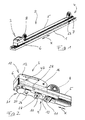
- suitable composite fastening device 2 comprises a first fastening device 3 and a second fastening device 4.
- the two fastening devices 3 and 4, of which the first fastening device 3 is typically associated with the rear side of the seat to be installed and the second fastening device 4 with its front side are connected by means of a tunnel-shaped spacer 5, which is the main body 6 and 7 of the two fastening devices 3 and 4 fixedly connected to each other, kept at a predetermined distance from each other.
- the base body 6 which can be placed on the hole-latching rail 1 has several functions. On the one hand, it serves, as a kind of housing, the inclusion of various functionally relevant components of the fastening device. At him the adjusting serving operating and operating mechanism is still stored. Finally, a holder 8, which is arranged on top of the main body 6 and on which, for example, the frame of a seat is to be attached, forms an integral part of the main body 6.
- a locking body 9 is slidably guided guided in the longitudinal direction X of the hole-locking rail 1, wherein the locking body protrudes partially downward from the base body 6.
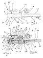
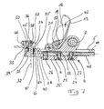
- the bolt body is displaceable between a first and a second end position, namely between the in the Fig. 2 to 4 shown locking position on the one hand and in the Fig. 5 to 7 shown assembly position on the other.
- the pivoting movement of the operating lever 13 is connected via a first gear 17 which is rotatably connected via corresponding flats 18 and 19 on the gear 17 and on the operating lever 13 with the latter, and a meshing with the first gear 17, rotatably mounted about the axis 20, serving as Umlenk leopardrad second gear 21 is transmitted to a rack 22 which is fixedly connected to the latch body 9.
- the rack 22 is inserted into a corresponding receiving recess 23 of the locking body 9 and fixed there with screws. Due to the described coupling of control lever 13 and locking body 9, the pivoting movement (A, B) of the operating lever 13 is converted into a displacement movement (arrows C and D) of the locking body.
- the locking body 9 consists of a guided in the base body 6 first element 24 and a three locking elements 11 having second element 25, wherein the distance a between the first element 24 and the second element 25 is adjustable.
- the first and the second element 24 and 25 of the locking body 9 via a two opposing threaded portions having adjusting screw 26 and two - only tensile forces transmitted - screws 27 connected to each other.
- the adjusting screw 26 is in the mounting position of the locking body ( Fig. 5 to 7 ) From above, ie the operating lever 13 side facing out to operate. Pressed locking pins 29, which may consist in particular of plastic, secure the set screw positions.
- a latching element 30 designed as a latching element 31 is further slidably guided, in the direction of the longitudinal axis X of the hole-latching rail 1 perpendicular axis 32.
- the locking pin 30 is displaceable between two end positions, namely between a (in the Fig. 2 to 4 shown) lowered normal position in which it can engage in a recess of the hole-locking rail 1, and a (in the Fig. 5 to 7 shown) raised displacement position in which no interference with the hole-locking rail 1 is possible.
- the sliding movement of the locking bolt 30 is independent of the locking body 9; It is accomplished via a separate, in this case designed as an actuating lever 33 actuator.
- the actuating lever 33 has an eccentric mechanism with an approximately semicircular sliding surface 34, which is slidably supported on a contact surface 35 of the base body 6, and an eccentric to the sliding surface 34 arranged eccentric 36.
- the latter engages in a slot 37 which is disposed on an upper extension 38 of the locking bolt 30 and parallel to the axis 32 extends.
- This allows the locking pin 30 also in the position corresponding to the normal position of the actuating lever 33 (FIG. Fig. 2 to 4 ) its raised, not in the hole-locking rail 1 engaging position ( Fig. 5 to 7 ) can take, especially if the locking pin is not exactly above a recess of the hole-locking rail 1.
- the locking bolt is biased by means of a detent spring 39 realized spring means F in its lowered position ("normal position"), so that when the operating lever 33 assumes the normal position of the locking bolt 30 corresponding position ( Fig. 2 to 4 ), immediately engages in a recess of the hole-locking rail when it is aligned with such.
- the operating lever In order to raise the locking pin 30 in its "sliding position" and to bring out of engagement with the hole-locking rail 1, in particular to the fastening device 3 on the hole-latching rail 1 resting along this move, the operating lever in his in the Fig. 5 to 7 pivoted position shown.
- the latch body 9 itself is prevented from assuming the locking position, namely by the nose-shaped blocking element 40 arranged on the front side of the latch body 9, which latchingly cooperates with the latching element upper end face 41 of the locking bolt 30, which forms in this way a second, corresponding blocking element 50, is determined.
- the two cooperating locking elements 40 and 50 prevent when the fastening device 3 assumes its operating position, moreover, a lifting of the locking bolt 30 against the force of the detent spring 39th
- the operating lever engages as an additional backup such that it can only be reopened using tools, ie can be pivoted upwards.
- a locking pin 42 passing through the operating lever 13 engages behind the two pawls 43 of a twin lever 44, which is pivotably mounted on the actuating lever 33 about the axis 45 and is biased into its locking position by means of the twin spring 46.
- the locking of the operating lever 13 can be solved by the twin lever 44 is slightly rotated by a tool about its axis 45 against the bias of the twin spring 46.
- the Control lever 13 on both sides in each case one - in the operating position - aligned with the axis 45 recess 47, through which the tool in question can be placed on the twin lever 44.
- a locking spring 48 is clamped between the locking body 9 and a support plate 49 arranged on the spacer 5. It biases the locking body 9 in its locking position.
- a coupling rod 52 is slidably received in the longitudinal direction of the spacer 5.
- the coupling rod 52 is fixedly connected via a threaded portion 51 to the upper, first element 24 of the locking body 9 of the first fastening device 3.
- the coupling rod 52 in a corresponding manner with the - in the base body 7 of the second fastening device 4 in the longitudinal direction of the hole-locking rail 1 slidably guided - locking body 53 is firmly connected.
Landscapes
- Engineering & Computer Science (AREA)
- Aviation & Aerospace Engineering (AREA)
- Transportation (AREA)
- Mechanical Engineering (AREA)
- Seats For Vehicles (AREA)
Applications Claiming Priority (1)
| Application Number | Priority Date | Filing Date | Title |
|---|---|---|---|
| DE201120108804 DE202011108804U1 (de) | 2011-12-08 | 2011-12-08 | Befestigungsvorrichtung |
Publications (1)
| Publication Number | Publication Date |
|---|---|
| EP2602190A2 true EP2602190A2 (fr) | 2013-06-12 |
Family
ID=45769422
Family Applications (1)
| Application Number | Title | Priority Date | Filing Date |
|---|---|---|---|
| EP20120008175 Withdrawn EP2602190A2 (fr) | 2011-12-08 | 2012-12-07 | Dispositif de fixation |
Country Status (2)
| Country | Link |
|---|---|
| EP (1) | EP2602190A2 (fr) |
| DE (1) | DE202011108804U1 (fr) |
Cited By (4)
| Publication number | Priority date | Publication date | Assignee | Title |
|---|---|---|---|---|
| GB2517149A (en) * | 2013-08-12 | 2015-02-18 | Nmi Safety Systems Ltd | Adaptable vehicle seat fitting |
| US9878639B2 (en) | 2015-06-01 | 2018-01-30 | Nmi Safety Systems Limited | Adaptable vehicle seat fitting |
| CN108583905A (zh) * | 2018-07-20 | 2018-09-28 | 中国民用航空总局第二研究所 | 一种航空座椅地脚锁紧装置 |
| CN109204832A (zh) * | 2017-06-29 | 2019-01-15 | 波音公司 | 旋转接合的快速安装轨道配件 |
Families Citing this family (6)
| Publication number | Priority date | Publication date | Assignee | Title |
|---|---|---|---|---|
| DE102012205467A1 (de) * | 2012-04-03 | 2013-10-10 | Airbus Operations Gmbh | Vorrichtung sowie Verfahren zur Montage einer Klemmeinrichtung in einer Profilschiene |
| US9789966B2 (en) | 2012-09-04 | 2017-10-17 | Zodiac Seats France | Aircraft seat attachment system provided with a system for locking an activation lever and/or for maintaining a clamping force by friction |
| FR3005450B1 (fr) * | 2013-05-10 | 2016-11-04 | Zodiac Seats France | Attache de siege d'aeronef muni d'un systeme de maintien par friction d'un effort de serrage |
| DE102013103435A1 (de) * | 2013-04-05 | 2014-10-09 | Recaro Aircraft Seating Gmbh & Co. Kg | Sitzbefestigung |
| DE102013109049A1 (de) | 2013-08-21 | 2015-02-26 | Airbus Operations Gmbh | Befestigungssystem zum Befestigen eines Objekts in einem Raum eines Verkehrsmittels und Verkehrsmittel mit einem Raum und mindestens einem derartigen Befestigungssystem |
| DE102018110892A1 (de) * | 2018-05-07 | 2019-11-07 | Recaro Aircraft Seating Gmbh & Co. Kg | Flugzeugsitzbefestigungsvorrichtung |
Citations (2)
| Publication number | Priority date | Publication date | Assignee | Title |
|---|---|---|---|---|
| EP0583295B1 (fr) | 1991-04-27 | 1994-11-23 | MICHLER, Walter | Dispositif de fixation rapide |
| DE102008048745A1 (de) | 2008-09-24 | 2010-05-12 | Airbus Deutschland Gmbh | Arretiervorrichtung für ein an einer Schiene arretierbares Objekt |
-
2011
- 2011-12-08 DE DE201120108804 patent/DE202011108804U1/de not_active Expired - Lifetime
-
2012
- 2012-12-07 EP EP20120008175 patent/EP2602190A2/fr not_active Withdrawn
Patent Citations (2)
| Publication number | Priority date | Publication date | Assignee | Title |
|---|---|---|---|---|
| EP0583295B1 (fr) | 1991-04-27 | 1994-11-23 | MICHLER, Walter | Dispositif de fixation rapide |
| DE102008048745A1 (de) | 2008-09-24 | 2010-05-12 | Airbus Deutschland Gmbh | Arretiervorrichtung für ein an einer Schiene arretierbares Objekt |
Cited By (7)
| Publication number | Priority date | Publication date | Assignee | Title |
|---|---|---|---|---|
| GB2517149A (en) * | 2013-08-12 | 2015-02-18 | Nmi Safety Systems Ltd | Adaptable vehicle seat fitting |
| EP2837526A1 (fr) * | 2013-08-12 | 2015-02-18 | NMI Safety Systems Ltd. | Garniture de siège de véhicule adaptable |
| GB2517149B (en) * | 2013-08-12 | 2020-03-04 | Nmi Safety Systems Ltd | Adaptable vehicle seat fitting |
| US9878639B2 (en) | 2015-06-01 | 2018-01-30 | Nmi Safety Systems Limited | Adaptable vehicle seat fitting |
| CN109204832A (zh) * | 2017-06-29 | 2019-01-15 | 波音公司 | 旋转接合的快速安装轨道配件 |
| CN108583905A (zh) * | 2018-07-20 | 2018-09-28 | 中国民用航空总局第二研究所 | 一种航空座椅地脚锁紧装置 |
| CN108583905B (zh) * | 2018-07-20 | 2024-01-05 | 中国民用航空总局第二研究所 | 一种航空座椅地脚锁紧装置 |
Also Published As
| Publication number | Publication date |
|---|---|
| DE202011108804U1 (de) | 2012-01-27 |
Similar Documents
| Publication | Publication Date | Title |
|---|---|---|
| EP2602190A2 (fr) | Dispositif de fixation | |
| EP3870786B1 (fr) | Serrure conçue pour un véhicule automobile, en particulier serrure de véhicule automobile à actionnement électrique | |
| EP0583295B1 (fr) | Dispositif de fixation rapide | |
| EP2142428B1 (fr) | Dispositif servant a fixer des objets | |
| WO1998007587A1 (fr) | Dispositif d'accouplement pour un vehicule | |
| EP3552874B1 (fr) | Siège de véhicule pourvu de console de changement de vitesses réglable | |
| DE102017116187A1 (de) | Schnelltrenn-Befestigungssystem zur Anbringung eines Wandgeräts abnehmbar an einer Struktur | |
| DE102019135374B4 (de) | Schiene für einen Fahrzeugsitz und Fahrzeugsitz mit einer derartigen Schiene | |
| WO2017103049A1 (fr) | Dispositif pour la fixation détachable d'un parement frontal et procédé de montage et de démontage d'un parement frontal | |
| DE69700556T2 (de) | Nach vorn bewegbarer Fahrzeugsitz, um zu einem hinteren Raum zu gelangen | |
| DE102017200646B4 (de) | Fahrzeug-Sitzanordnung und Easy-Entry-Löse-System | |
| EP2053010B1 (fr) | Dispositif de verrouillage | |
| DE212023000274U1 (de) | System zur Arretierung einer stufenlos verstellbaren Gleitschiene | |
| EP3911553A1 (fr) | Colonne de direction pour un véhicule automobile | |
| DE102007014420A1 (de) | Vorrichtung zum Festlegen von Gegenständen | |
| DE102020207924B3 (de) | Verriegelungsvorrichtung für einen Fahrzeugsitz mit einem ein Verriegelungselement in einer Verriegelungsposition formschlüssig sichernden Sicherungsabschnitt, Verriegelungsbaugruppe und Fahrzeugsitz mit einer derartigen Verriegelungsvorrichtung | |
| EP2252510B1 (fr) | Procede de fixation d'un objet sur un rail | |
| EP2451728B1 (fr) | Colonne d' empilage | |
| DE102011112305A1 (de) | Sitzanordnung für ein Kraftfahrzeug mit einer Zwangsführung für einen Fahrzeugsitz | |
| WO2023031079A1 (fr) | Ensemble siège, véhicule et procédé d'installation utilisant une pièce supplémentaire pour fixer un autre composant dans l'habitacle du véhicule | |
| EP2305526A1 (fr) | Dispositiv actionneur | |
| EP2331365B1 (fr) | Dispositif de réglage pour le réglage en hauteur, en particulier pour le réglage de la hauteur de coussins pour sièges de véhicules à moteur | |
| DE102009039349A1 (de) | Sitzverriegelungsvorrichtung | |
| EP2859869B1 (fr) | Dispositif destiné à la liaison coulissante d'un siège passager à une structure de véhicule | |
| EP3741257A1 (fr) | Dispositif de verrouillage |
Legal Events
| Date | Code | Title | Description |
|---|---|---|---|
| PUAI | Public reference made under article 153(3) epc to a published international application that has entered the european phase |
Free format text: ORIGINAL CODE: 0009012 |
|
| AK | Designated contracting states |
Kind code of ref document: A2 Designated state(s): AL AT BE BG CH CY CZ DE DK EE ES FI FR GB GR HR HU IE IS IT LI LT LU LV MC MK MT NL NO PL PT RO RS SE SI SK SM TR |
|
| AX | Request for extension of the european patent |
Extension state: BA ME |
|
| STAA | Information on the status of an ep patent application or granted ep patent |
Free format text: STATUS: THE APPLICATION IS DEEMED TO BE WITHDRAWN |
|
| 18D | Application deemed to be withdrawn |
Effective date: 20170701 |