EP2602584A1 - Système de mesure optique - Google Patents
Système de mesure optique Download PDFInfo
- Publication number
- EP2602584A1 EP2602584A1 EP11191963.5A EP11191963A EP2602584A1 EP 2602584 A1 EP2602584 A1 EP 2602584A1 EP 11191963 A EP11191963 A EP 11191963A EP 2602584 A1 EP2602584 A1 EP 2602584A1
- Authority
- EP
- European Patent Office
- Prior art keywords
- measuring system
- optical
- light
- light beam
- optical measuring
- Prior art date
- Legal status (The legal status is an assumption and is not a legal conclusion. Google has not performed a legal analysis and makes no representation as to the accuracy of the status listed.)
- Withdrawn
Links
- 230000003287 optical effect Effects 0.000 title claims abstract description 78
- 238000003384 imaging method Methods 0.000 claims abstract description 39
- 230000000007 visual effect Effects 0.000 claims abstract description 34
- 238000012545 processing Methods 0.000 claims abstract description 9
- 239000003086 colorant Substances 0.000 claims description 2
- 238000011156 evaluation Methods 0.000 claims description 2
- 238000005259 measurement Methods 0.000 abstract description 6
- 238000012360 testing method Methods 0.000 description 20
- 239000000523 sample Substances 0.000 description 5
- 239000003550 marker Substances 0.000 description 3
- VYZAMTAEIAYCRO-UHFFFAOYSA-N Chromium Chemical compound [Cr] VYZAMTAEIAYCRO-UHFFFAOYSA-N 0.000 description 2
- 238000011511 automated evaluation Methods 0.000 description 2
- 230000007423 decrease Effects 0.000 description 2
- 239000011521 glass Substances 0.000 description 2
- 230000005484 gravity Effects 0.000 description 2
- 238000000034 method Methods 0.000 description 2
- 229910052804 chromium Inorganic materials 0.000 description 1
- 239000011651 chromium Substances 0.000 description 1
- 238000011161 development Methods 0.000 description 1
- 230000008447 perception Effects 0.000 description 1
- 239000000758 substrate Substances 0.000 description 1
Images

Classifications
-
- G—PHYSICS
- G01—MEASURING; TESTING
- G01B—MEASURING LENGTH, THICKNESS OR SIMILAR LINEAR DIMENSIONS; MEASURING ANGLES; MEASURING AREAS; MEASURING IRREGULARITIES OF SURFACES OR CONTOURS
- G01B11/00—Measuring arrangements characterised by the use of optical techniques
- G01B11/24—Measuring arrangements characterised by the use of optical techniques for measuring contours or curvatures
- G01B11/25—Measuring arrangements characterised by the use of optical techniques for measuring contours or curvatures by projecting a pattern, e.g. one or more lines, moiré fringes on the object
- G01B11/2513—Measuring arrangements characterised by the use of optical techniques for measuring contours or curvatures by projecting a pattern, e.g. one or more lines, moiré fringes on the object with several lines being projected in more than one direction, e.g. grids, patterns
Definitions
- the invention relates to an optical measuring system, in particular non-contact optical surface measuring system, with an image processing unit and an imaging optics.
- optical measuring systems in particular non-contact surface measuring systems, such as e.g. optical 3D measuring systems (in particular measuring systems measuring areally), a specific area on the surface of the test object is generally of interest.
- tactile measuring systems in which the current measuring position of the measuring system can be clearly recognized by the operator via a measuring probe, this is not readily possible with non-contact measuring systems. Aligning the measuring system and the test piece with each other is very difficult.
- This problem is particularly difficult if the measuring system does not work with visible light to illuminate the specimen or the light source used diffusely illuminates the surface over a large area, so that no connection between illuminating light spot and the measuring field on the specimen is recognizable.
- Some measuring systems of the prior art have a dedicated positioning sensor for positioning the measuring sensor system. This can e.g. to be a calibrated macroscopic video camera. Their image, which the operator can see on a video screen, can be e.g. By means of a crosshair superimposed on the image, the measuring position can be targeted.
- the object of the present invention is therefore to overcome the disadvantages of the prior art.
- the object of the invention is to provide an optical measuring system in which the operator is assisted in the relative positioning between the measuring system and a DUT by non-contact means.
- the present invention solves this problem by providing an optical measuring system, in particular a contactless optical surface measuring system, having the features of claim 1.
- non-contact optical measurement system is to be understood as meaning that a specimen, such as a test specimen, e.g. a workpiece is measured without this specimen must be touched with probes or the like. Rather, there is an optical observation (image acquisition) and measurement with image processing means.
- the optical measuring system according to the invention for measuring a test object comprises an image processing unit and an imaging optics.
- a light source which - optionally by optical means, such as e.g. Lenses or mirrors, a visual marker projected into a measuring field of the imaging optics.
- this visual marking is designed to allow both lateral and vertical alignment of the device under test and the measuring system.
- the projection of the visual marking is directed to the center of the measuring field or defines the outline of the measuring field.
- the light source in particular a laser or a light-emitting diode, emits a first narrow light beam as a visual marking, which is directed into the measuring field parallel or coaxially to the optical axis of the imaging optics.
- Both lasers and light emitting diodes represent well-localized light sources.
- the light beam emitted by these light sources has a high degree of parallelism, in particular in the case of the laser.
- the light beam is preferably at least partially coupled coaxially into the beam path of the measuring system so that it leaves the measuring system parallel to its optical axis or coincident with it in the direction of the test object.
- the light spot projected onto the surface of the specimen by the light beam represents the visual mark which lies in the center of the measuring field or is displaced at a predefined distance from the center of the measuring field.
- a further development of the invention provides that an additional light source generates a second narrow light beam and is projected obliquely to the first light beam into the measuring field, the first and the second light beam being aligned in this way they are intersect each other in the focal plane of the imaging optics. It is therefore necessary to align the measuring system and the test object only in such a way that both light spots of the two light beams on the surface of the test object coincide in one point.
- different colored light sources or light beams eg red and green
- the light source in particular a laser or a light emitting diode, emits a convergent light beam as a visual marking, which is directed parallel or coaxial to the optical axis of the imaging optics in the measurement field and is maximally focused in the focal plane of the imaging optics .
- the visual marking projected onto the test object by the light beam in the form of a light spot will therefore reach its minimum extent when the test object or the surface of the test object illuminated by the light beam is in the focus of the imaging Optics is located.
- the size of the visual marker may e.g. be tracked via a camera installed in the measuring system or also via an external camera.
- the user can thus easily follow via the camera image displayed on a monitor, whether the DUT is in focus or not.
- the camera image can also be evaluated by image processing software and determined with the aid of the image processing software, if the test object has reached the focus range of the optical measuring system. This can then be e.g. be reported via a stop signal to aticianlings-positioning of the measuring system or a measuring system positioning mechanism to end the positioning process.
- the direction in which you have to move the positioning mechanism to reach the focus area can be easily determined. If you e.g. If the measuring system moves towards the sample and the size of the projected light spot decreases, the direction of movement is in the direction of the focus area, otherwise the direction must be reversed.
- the light source in particular a laser or a light-emitting diode, emits a light beam as a visual mark, which is directed obliquely to the optical axis of the imaging optics in the measurement field and is preferably focused in the focal plane of the imaging optics, which for example by a corresponding adjustment of the Einkopplungsraum of the light beam in the coaxial optical path of the imaging optics is easily possible, so can from the offset of the center of gravity of the light spot, ie the visual mark, to the main point of the camera image (that is, the point where an object point, which lies on the optical axis, in the camera image) the distance between the Focus plane of the imaging optics and the DUT are calculated.
- the positioning of the specimen in the focal plane of the measuring system can be done even more targeted.
- a coaxial laser beam is sufficient for the mere sighting of the measuring position on the test object.
- the light source emits an intensity-modulated light beam as a visual marking, which projects a light pattern into the measuring field.
- the visual mark may be in the form of projection of a binary mask.
- a binary chromium mask on a glass substrate-similar to a slide-is illuminated from behind The resulting intensity modulation is imaged onto the surface of the test object with the aid of suitable optics.
- the light pattern projected in this way marks the measuring field of the measuring system.
- the pattern is ideally focused in the focal plane of the measurement system so that vertical alignment is also possible by focusing the pattern on the sample surface. Again, an automated evaluation of this pattern on a camera image can be realized with the automated focusing on a positioning system is created.
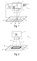
- FIG. 1 Reference is made schematically in a first embodiment of an inventive optical measuring system 1, which is designed as a non-contact optical surface measuring system is shown.
- the measuring system 1 comprises a Image processing unit 2 and an imaging optics 3.
- a light source 4 which is formed for example as a laser or light emitting diode, generates a light beam 5 of high parallelism, which is coupled via a mirror 6 or other optical means in the beam path of the imaging optical system 3.
- the light beam 5 leaves the imaging optical system 3 parallel to the optical axis 3a of the imaging optical system 3 and projects a - in this example punctiform - visual mark 5a in a measuring field 7 of the imaging optical system 3.
- the light beam 5 parallel to the optical axis 3a of the imaging Optics 3 is directed, it is slightly laterally offset from the center 7 a of the measuring field 7 on the measuring field 7.
- an additional light source 8 is provided, with which a second narrow light beam 9 is generated, which is optionally projected by means not shown optical devices such as lenses, mirrors, etc. obliquely to the first light beam 5 in the measuring field 7, wherein the first and second light beams 5, 9 are aligned to intersect each other in the focal plane 3b of the imaging optics 3.
- the focal plane 3b coincides here with the plane of the measuring field 7.
- the second light beam 9 produces a light spot 9a which coincides with the visual mark 5a in the focal plane 3b. So that a user can more easily recognize which light spot is generated by which light beam, it is expedient if the first light beam 5 and the second light beam 9 have different colors.
- the positioning of the measuring field 7 or a test object, not shown, arranged in the measuring field 7, can be carried out manually by means of the procedure described above of bringing the two light spots into agreement. But it can also be facilitated by the provision of a camera 10, whereby the user can follow through the camera image displayed on a monitor, whether the two luminous points 5a, 9a coincide and thus the measuring field 7 has been brought into line with the focal plane 3b.
- the camera images taken by the camera 10 are supplied to image processing means 11 which evaluate the camera images in relation to the size and / or focusing and / or relative position of the visual mark 5a with respect to a reference position, and preferably also a sample positioning device 12 according to the evaluation of the camera images control.
- either the first light beam 5 is slightly oblique to the optical axis 3a of the imaging optics 3 or only the second light beam 9 is used for positioning the measuring field 7 or a test object arranged thereon.
- the offset between the center of gravity of the visual mark 5a or the spot 9a to the main point of the camera image can be the distance between the Burning plane 3b of the imaging optics and the measuring field 7 or the DUT positioned thereon can be calculated.
- the positioning of the specimen in the focal plane 3b of the measuring system 1 can be made even more targeted.
- the convergent light beam 5" ' is directed obliquely to the optical axis 3a of the imaging optical system 3 into the measuring field 7.
Landscapes
- Engineering & Computer Science (AREA)
- Computer Vision & Pattern Recognition (AREA)
- Physics & Mathematics (AREA)
- General Physics & Mathematics (AREA)
- Length Measuring Devices By Optical Means (AREA)
Priority Applications (1)
| Application Number | Priority Date | Filing Date | Title |
|---|---|---|---|
| EP11191963.5A EP2602584A1 (fr) | 2011-12-05 | 2011-12-05 | Système de mesure optique |
Applications Claiming Priority (1)
| Application Number | Priority Date | Filing Date | Title |
|---|---|---|---|
| EP11191963.5A EP2602584A1 (fr) | 2011-12-05 | 2011-12-05 | Système de mesure optique |
Publications (1)
| Publication Number | Publication Date |
|---|---|
| EP2602584A1 true EP2602584A1 (fr) | 2013-06-12 |
Family
ID=45372212
Family Applications (1)
| Application Number | Title | Priority Date | Filing Date |
|---|---|---|---|
| EP11191963.5A Withdrawn EP2602584A1 (fr) | 2011-12-05 | 2011-12-05 | Système de mesure optique |
Country Status (1)
| Country | Link |
|---|---|
| EP (1) | EP2602584A1 (fr) |
Cited By (2)
| Publication number | Priority date | Publication date | Assignee | Title |
|---|---|---|---|---|
| CN107421473A (zh) * | 2017-05-26 | 2017-12-01 | 南京理工大学 | 基于图像处理的两束激光同轴度检测方法 |
| CN111536872A (zh) * | 2020-05-12 | 2020-08-14 | 河北工业大学 | 基于视觉的二维平面测距装置及方法、标记点识别装置 |
Citations (7)
| Publication number | Priority date | Publication date | Assignee | Title |
|---|---|---|---|---|
| US5196900A (en) * | 1988-04-12 | 1993-03-23 | Metronor A.S. | Method and sensor for opto-electronic angle measurements |
| JPH05205097A (ja) * | 1992-01-28 | 1993-08-13 | Nippon Dry Chem Co Ltd | 画像入力装置と入力方法 |
| DE10037771A1 (de) * | 2000-08-03 | 2002-02-21 | Fraunhofer Ges Forschung | Verfahren und Vorrichtung zur Messung der Entfernung eines Objektes |
| EP1262810A2 (fr) * | 2001-05-29 | 2002-12-04 | Leica Microsystems AG | Méthode pour mesurer des distances d'objets étendus avec un dispositif optique d'observation et microscope l'utilisant |
| US20050237581A1 (en) * | 2004-04-21 | 2005-10-27 | Knighton Mark S | Hand held portable three dimensional scanner |
| US20080107309A1 (en) * | 2006-11-03 | 2008-05-08 | Cerni Consulting, Llc | Method and apparatus for biometric identification |
| FR2940423A1 (fr) * | 2008-12-22 | 2010-06-25 | Noomeo | Dispositif de numerisation tridimensionnelle a reconstruction dense |
-
2011
- 2011-12-05 EP EP11191963.5A patent/EP2602584A1/fr not_active Withdrawn
Patent Citations (7)
| Publication number | Priority date | Publication date | Assignee | Title |
|---|---|---|---|---|
| US5196900A (en) * | 1988-04-12 | 1993-03-23 | Metronor A.S. | Method and sensor for opto-electronic angle measurements |
| JPH05205097A (ja) * | 1992-01-28 | 1993-08-13 | Nippon Dry Chem Co Ltd | 画像入力装置と入力方法 |
| DE10037771A1 (de) * | 2000-08-03 | 2002-02-21 | Fraunhofer Ges Forschung | Verfahren und Vorrichtung zur Messung der Entfernung eines Objektes |
| EP1262810A2 (fr) * | 2001-05-29 | 2002-12-04 | Leica Microsystems AG | Méthode pour mesurer des distances d'objets étendus avec un dispositif optique d'observation et microscope l'utilisant |
| US20050237581A1 (en) * | 2004-04-21 | 2005-10-27 | Knighton Mark S | Hand held portable three dimensional scanner |
| US20080107309A1 (en) * | 2006-11-03 | 2008-05-08 | Cerni Consulting, Llc | Method and apparatus for biometric identification |
| FR2940423A1 (fr) * | 2008-12-22 | 2010-06-25 | Noomeo | Dispositif de numerisation tridimensionnelle a reconstruction dense |
Cited By (2)
| Publication number | Priority date | Publication date | Assignee | Title |
|---|---|---|---|---|
| CN107421473A (zh) * | 2017-05-26 | 2017-12-01 | 南京理工大学 | 基于图像处理的两束激光同轴度检测方法 |
| CN111536872A (zh) * | 2020-05-12 | 2020-08-14 | 河北工业大学 | 基于视觉的二维平面测距装置及方法、标记点识别装置 |
Similar Documents
| Publication | Publication Date | Title |
|---|---|---|
| DE102013227101B3 (de) | Optisches System zur Nachverfolgung eines Ziels | |
| DE102005022095B4 (de) | Verfahren und Vorrichtung zur Bestimmung einer lateralen Relativbewegung zwischen einem Bearbeitungskopf und einem Werkstück | |
| DE102011016519B4 (de) | Vorrichtung zur Bearbeitung eines Werkstücks mittels eines hochenergetischen Bearbeitungsstrahls | |
| EP2847540B1 (fr) | Module d'éclairage amélioré pour un appareil de mesure de coordonnées | |
| DE102014108353A1 (de) | Verfahren und Vorrichtung zur Bestimmung von Geometrien an Messobjekten mittels eines kombinierten Sensorsystems | |
| DE102019120398B3 (de) | Laserbearbeitungssystem und Verfahren für eine zentrische Ausrichtung eines Laserstrahls in einem Bearbeitungskopf eines Laserbearbeitungssystems | |
| EP2131145B1 (fr) | Dispositif de surveillance optique | |
| WO2015082683A2 (fr) | Dispositif et procédé pour la mesure de pièces | |
| WO2015036026A1 (fr) | Procédé et dispositif de mesure de taraudages d'une pièce usinée au moyen d'un capteur optique | |
| EP3581881A1 (fr) | Mesure de surface au moyen de la fluorescence excitée | |
| DE4136002A1 (de) | Moire- konturenabbildungsvorrichtung | |
| DE102016007586A1 (de) | Neuartige Vorrichtung/en zum automatischen Aufbringen oder Erzeugen und Überwachen einer auf einem Substrat aufgebrachten Struktur mit Ermittlung von geometrischen Abmessungen sowie ein entsprechendes Verfahren | |
| WO2019120557A1 (fr) | Dispositif optique d'application ou de production et de surveillance automatiques d'une structure déposée sur un substrat avec détermination de dimensions géométriques et procédé correspondant | |
| DE102017211680B4 (de) | Optischer Sensor und Verfahren zur Positionierung, Fokussierung und Beleuchtung | |
| DE102015109960B4 (de) | Vorrichtung und Verfahren zum optischen Bestimmen einer Position und/oder Orientierung eines Manipulators | |
| EP3502614B1 (fr) | Dispositif de mesure optique | |
| EP2602584A1 (fr) | Système de mesure optique | |
| DE102011052586B4 (de) | Prägekopf mit Positionierungshilfe | |
| EP3303990B1 (fr) | Commande d'éclairage lors de l'utilisation d'appareils de mesure optiques | |
| DE102014112872A1 (de) | Vorrichtung zum Abbilden von Fingerabdrücken | |
| DE102013202349B3 (de) | Kohärenzrasterinterferometer und Verfahren zur ortsaufgelösten optischen Vermessung der Höhengeometriedaten eines Objekts | |
| DE102017009334B3 (de) | Verfahren zum Prüfen eines optischen Systems | |
| EP1136787B1 (fr) | Reproduction d'un objet avec compensation de la distance ( taille, couleur ) | |
| DE4217430A1 (de) | Aufnahme-Einrichtung zum Erfassen und Darstellen zu vergleichender Objekte | |
| EP1243958A2 (fr) | Procédé de réglage d'un microscope et microscope ayant un dispositif d'ajustage pour le faisceau lumineux |
Legal Events
| Date | Code | Title | Description |
|---|---|---|---|
| PUAI | Public reference made under article 153(3) epc to a published international application that has entered the european phase |
Free format text: ORIGINAL CODE: 0009012 |
|
| AK | Designated contracting states |
Kind code of ref document: A1 Designated state(s): AL AT BE BG CH CY CZ DE DK EE ES FI FR GB GR HR HU IE IS IT LI LT LU LV MC MK MT NL NO PL PT RO RS SE SI SK SM TR |
|
| AX | Request for extension of the european patent |
Extension state: BA ME |
|
| STAA | Information on the status of an ep patent application or granted ep patent |
Free format text: STATUS: THE APPLICATION IS DEEMED TO BE WITHDRAWN |
|
| 18D | Application deemed to be withdrawn |
Effective date: 20131213 |