EP2602802A1 - Verfahren zur Herstellung einer Isolierung einer Spannungsspule eines Hochspannungsinstrumententransformators und Vorrichtung zur Herstellung der Isolierung einer Spannungsspule - Google Patents
Verfahren zur Herstellung einer Isolierung einer Spannungsspule eines Hochspannungsinstrumententransformators und Vorrichtung zur Herstellung der Isolierung einer Spannungsspule Download PDFInfo
- Publication number
- EP2602802A1 EP2602802A1 EP12460073.5A EP12460073A EP2602802A1 EP 2602802 A1 EP2602802 A1 EP 2602802A1 EP 12460073 A EP12460073 A EP 12460073A EP 2602802 A1 EP2602802 A1 EP 2602802A1
- Authority
- EP
- European Patent Office
- Prior art keywords
- coil
- insulation
- voltage coil
- crossbar
- voltage
- Prior art date
- Legal status (The legal status is an assumption and is not a legal conclusion. Google has not performed a legal analysis and makes no representation as to the accuracy of the status listed.)
- Granted
Links
Images


Classifications
-
- H—ELECTRICITY
- H01—ELECTRIC ELEMENTS
- H01F—MAGNETS; INDUCTANCES; TRANSFORMERS; SELECTION OF MATERIALS FOR THEIR MAGNETIC PROPERTIES
- H01F27/00—Details of transformers or inductances, in general
- H01F27/28—Coils; Windings; Conductive connections
- H01F27/32—Insulating of coils, windings, or parts thereof
- H01F27/324—Insulation between coil and core, between different winding sections, around the coil; Other insulation structures
Definitions
- the invention deals with a method for making the insulation of a voltage coil of an HV instrument transformer and a device for making this insulation, applicable to isolating the voltage coil with insulating paper during the process of coil banding occurring during the production of a voltage transformer and during the production of a combined instrument transformer comprised of a current transformer and a voltage transformer.
- the main insulation and the interlayer insulation of a voltage coil and of a high voltage bushing is insulating paper.
- This insulation is made by winding in successive turns a layer of winding and applying a layer of insulating paper with paper edges cut longitudinally in relation to the tube axis, further on referred to as fringes, onto the insulating tube of the high voltage coil.
- the winding of the high voltage coil has the shape of a trapeze, whereas the paper insulation has the shape similar to a cylinder.
- banding After winding, the coil is moved to the banding station. A top screen is applied onto the coil symmetrically in relation to the ends of the tube and the formation of the main insulation, further on referred to as banding, starts in horizontal position. Banding takes place as follows. Several paper layers with fringes on the right side of the winding are folded onto the top screen and fixed by gluing individual fringes from paper layers from the other side. Next, several paper layers with fringes on the left side of the winding are folded onto the top screen and fixed by gluing individual fringes from paper layers from the other side. The pasted layers are additionally fixed with crepe paper by enveloping the coil on its circumference with serpentine movements until the coil surface is completely covered with paper. These operations are repeated until the coil reaches a suitable diameter.
- a conducting bar containing paper insulation with equipotential screens is screwed into a sleeve located in the top screen. Further application of paper insulation and equipotential screens onto the conducting bar is done concurrently with banding the coil. The operations of banding the coil are repeated, only now, after each wrapping of the coil surface with crepe paper, further winding of the bushing follows. Banding of the coil and winding of the bushing take place by turns, so that the bushing insulation and the coil insulation overlap, which greatly affects the withstand voltage.
- Making of the external screen starts after the completion of banding.
- the external screen is made of thin aluminum foil and it is located on the upper part of the coil having a bell-like shape.
- the edge of the screen ends with a band of a conducting material, to eliminate sharp edges.
- the presented insulation-making process is carried out manually, which is very laborious and requires considerable manual skills from the person performing these actions.
- the horizontal situation of the voltage coil during banding and breaking of the fixing paper band results in a free fall of the fringes due to gravitation.
- the fringes have to be picked up, straightened, and the paper fringes have to be manually stretched and glued alternately on the left and on the right.
- the falling of the fringes and their manual picking-up results in folding and uneven arrangement of the paper insulation, which affects the withstand voltage of the insulation.
- the essence of the method of making the main insulation of the voltage coil of an HV instrument transformer according to the invention in which the insulating material are sheets of winding paper with longitudinally cut bands which are used to insulate first the individual layers of the voltage coil winding forming the interlayer insulation of the coil, and then to insulate the coil and the connection between the coil and the bushing of the HV instrument transformer, is that an upper screen is put on the insulated windings of the voltage coil, which screen is connected with a connecting bar of the bushing and then the coil and the place of connection of the voltage coil and the bushing is banded with bands of winding paper In vertical position of the coil, in turns from the upper and lower sides of the coil surface.
- the thickness of the layers of the voltage coil insulation decreases with the increase in the distance from the coil axis.
- a winding layer of semiconducting paper is applied on the external surface of the banded coil and the main insulation, forming an external screen of the instrument transformer.
- the external screen when the external screen has been applied on the banded coil and the main insulation, the external screen is wound with copper strap.
- the conducting bar together with the insulation take horizontal position.
- the coil and the screen as well as the connection between the voltage coil and the conducting bar is banded using a gravitational banding device.
- the essence of the device for making the main insulation of the voltage coil of a HV instrument transformer, comprising a crossbar and means for fixing the voltage coil with the main screen on the crossbar is that the crossbar of the device is fixed on a revolving frame joined with a body and a base.
- the device for making the main insulation contains a block mechanism for blocking the crossbar together with the frame in a horizontal or vertical position, with the crossbar and the frame revolving by an angle of 90°.
- a holder with a clamping ring for keeping the transformer bushing in vertical position is fixed to the body of the device.
- the device according to the invention contains a nut for adjusting the height of the frame position.
- the advantage of the method and device according to the invention is a significant facilitation in the process of making the insulation achieved by using the gravitational force for arranging the fringes while banding the coil in vertical position in the device, which also prevents crumpling and wrinkling of the fringes and facilitates their fixing to the surface of the coil.
- the fringes of the winding paper are not shifted in relation to one another and they form packets which can be easily arranged on the circumference of the coil during vertical banding of the coil.
- the use of a full external screen made of semi-conducting paper ensures equal spacing between high-potential coil elements and ground and it ensures a repeatable electric field distribution, and it also protects the coil against possible edges in the housing and other ground-potential elements.
- the advantage of the device for making insulation is a significant facilitation of the process of coil banding by keeping the coil in vertical position and by easy rotation of the coil by 180°. Also the installation of the external screen in the device in vertical position is easier and permits quick and uniform spreading of conducting tape on the external screen of the coil using two insulation discs fastened to the sides of the coil and thereby it ensures a uniform potential distribution on the voltage coil.
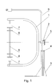
- fig. 1 shows the device for making insulation
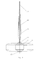
- fig. 2 shows the voltage coil together with insulating winding material after the completion of the coil winding process, in cross-section
- fig. 3 - detail "A" from fig. 2
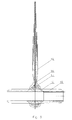
- fig. 4 - the voltage coil after connection with a HV bushing before starting the banding process, in cross-section
- fig. 5 the voltage coil partly banded together with the bushing, in cross-section
- fig. 6 the voltage coil together with the bushing after the completion of the winding process, in cross-section.
- the method of making the insulation of a voltage coil of a HV instrument transformer is first carried out on a traditional winding machine for voltage coil winding, and then by means of the device for making insulation according to the invention.
- the device for making insulation so called gravitationally insulating device, comprises a frame 1 of an arched shape, rigidly fixed to a revolving body 2 which is joined movably in vertical direction with a base 3 by a nut 4 which controls the regulation of the height of the position of the body 2.
- the revolving body 2 is provided with a blocking mechanism 5 used to block the position of the body together with the frame 1 with a revolution of 90°.
- the frame 1 comprises a crossbar 6 furnished with pressing sleeves 7 at its ends, and spacer disks 8.
- a holder 9 ending with a clamp for keeping the high voltage bushing in vertical position at the moment when the voltage coil is in horizontal position, useful during the further execution of the insulating process, e.g. during the application of the external screen.
- the process of insulating a voltage coil 10 takes place as follows.
- the first winding layer 12 is wound onto an insulating tube 11 constituting the coil carcass, and then insulation layers 13 and winding layers 12 are wound in turns, which is shown in fig. 3 , and the winding terminal 14 is lead out through a suitable port in the carcass and left outside the insulating tube 11.
- the direction of each next layer of winding is opposite to the previous direction.
- the insulation layer is formed of multiple sheets of paper wound on the insulating tube 11 and technological tubes 15. The sheets of paper are cut longitudinally and they form winding bands 16, also called fringes. Insulation packets differ in thickness, that is, in the number of sheets of insulating paper.
- the thickness of subsequent layers of insulation paper depends on the tension between subsequent layers, which in turn depends on the number of turns in the layer.
- the number of sheets in a layer is selected to keep the tension falling on one sheet of paper constant in all layers of paper.
- the thickness of the insulation layers 13 of the voltage coil 10 decreases with increase in their distance to the coil axis.
- insulation packets also differ in width, giving a gradated shape to a spool formed by the wound coil 10 and the insulation packets.
- a top screen 17 comprising a metal protective guard (a cone) being an element of the screen is put onto the coil 10.
- the coil 10 with paper insulation and with the screen 10 is mounted upon the crossbar 6 of the gravitationally insulating device whose frame 1 is placed in horizontal position, and the position of the coil 10 is immobilized on the crossbar 6 by means of clamping sleeves 7.
- the end of a conducting bar 18 which, with the exception of the ends, is enveloped in a paper insulation 19 containing equipotential screens 20 is fixed to the top screen 17 of the coil 10.
- the conducting bar 18 together with the insulation 19 forms a bushing of the high voltage instrument transformer.
- the frame 1 of the device When the coil 10 with the top screen 17 have been mounted on the crossbar 6 of the device, the frame 1 of the device is turned to vertical position, and after breaking the first tape that fixes the winding paper bands which are situated vertically above the coil, paper bands 16 of the first insulation packet are released, which bands fall gravitationally onto the upper surface of the coil 10.
- the bands 16, after being squared, are attached to the surface by means of crepe paper, not shown in the drawing, the first insulation layer being attached to the surface of the top screen 17 with minute amounts of glue.
- the revolving frame 1 of the device After attaching all bands of the given packet, after clipping and wrapping them in crepe paper, the revolving frame 1 of the device is turned by 180°, and after breaking another fixing tape, the paper bands 16 of the second insulation packet are released, achieving a free, gravitational fall of the bands 16 onto the bottom surface of the coil 10, which is now situated in the top position.
- the bands of the second packet are glued to the insulation layer obtained from the first packet of bands and made on the surface of the coil now situated in the bottom position.
- the revolving frame 1 of the device is turned again and another layer of insulation is fixed in the same way as before.
- the banding process includes application of paper insulation first on the coil 10, and then on the top screen 17 and on the uninsulated end of the conducting bar 18, at the place where it joins the coil 10. Insulation is applied in turns, so that insulation in the place where the HV bushing joins the voltage coil 10 interlaces with the insulation of the voltage coil 10, forming a main insulation 21 as a monolith without any gaps.
- the revolving frame 1 of the device is turned by an angle of 90° and the coil bushing is set in vertical position.
- another insulating stage starts, which is not shown in the drawing, in which an external screen of the coil is made in the form of a layer of semiconducting paper placed on the outer surface of the insulation of the coil 10 and its joint with the bushing.
- copper strap is coiled around the external screen using two insulating discs attached on the sides of the coil forming a zigzag braid on the outer surface of the coil, which is not shown in the drawing.
- More copper straps are coiled around the main insulation 21 screened with black semiconducting paper, on the joint between the HV bushing and the voltage coil 10, which is not shown in the drawing either. Cuts in all copper straps are soldered with filler metal. The application of copper strap permits an even potential distribution on the voltage coil.
- the method for banding a voltage coil according to the invention is carried out in vertical position of the coil, which reduces the labor consumption for making the coil and at the same time it improves banding quality.
- the vertical situation of the coil during banding causes that when the bands 16 of the first insulation packet, previously protected with girding bands, are released, the bands fall naturally, by gravitation, onto the top surface of the coil, without causing folds and they spread evenly on the coil circumference. Fastening the bands 16 to the surface of the coil is then much simpler and does not require so much strength and skill as in the case of banding in horizontal position.
- this method does not produce creases in the insulation and greatly reduces the need to use glue, since the bands take the right position by themselves, under its own weight.
- the insulation according to the invention has great electric break-down strength and small partial discharges, which is very important for the quality of a voltage transformer.
Landscapes
- Engineering & Computer Science (AREA)
- Power Engineering (AREA)
- Insulating Of Coils (AREA)
- Transformers For Measuring Instruments (AREA)
- Housings And Mounting Of Transformers (AREA)
- Coils Or Transformers For Communication (AREA)
Priority Applications (1)
| Application Number | Priority Date | Filing Date | Title |
|---|---|---|---|
| PL12460073T PL2602802T3 (pl) | 2011-12-05 | 2012-10-08 | Sposób wykonywania izolacji cewki napięciowej przekładnika WN i przyrząd do wykonywania izolacji cewki napięciowej |
Applications Claiming Priority (1)
| Application Number | Priority Date | Filing Date | Title |
|---|---|---|---|
| PL397241A PL221558B1 (pl) | 2011-12-05 | 2011-12-05 | Sposób wykonywania izolacji cewki napięciowej przekładnika WN i przyrząd do wykonywania izolacji cewki napięciowej |
Publications (3)
| Publication Number | Publication Date |
|---|---|
| EP2602802A1 true EP2602802A1 (de) | 2013-06-12 |
| EP2602802A8 EP2602802A8 (de) | 2013-07-24 |
| EP2602802B1 EP2602802B1 (de) | 2014-03-26 |
Family
ID=48539560
Family Applications (1)
| Application Number | Title | Priority Date | Filing Date |
|---|---|---|---|
| EP12460073.5A Active EP2602802B1 (de) | 2011-12-05 | 2012-10-08 | Verfahren zur Herstellung einer Isolierung einer Spannungsspule eines Hochspannungsinstrumententransformators und Vorrichtung zur Herstellung der Isolierung einer Spannungsspule |
Country Status (3)
| Country | Link |
|---|---|
| EP (1) | EP2602802B1 (de) |
| HR (1) | HRP20140578T1 (de) |
| PL (2) | PL221558B1 (de) |
Cited By (2)
| Publication number | Priority date | Publication date | Assignee | Title |
|---|---|---|---|---|
| CN108389707A (zh) * | 2018-02-05 | 2018-08-10 | 河南森源电气股份有限公司 | 电压互感器及其制造方法 |
| CN116344203A (zh) * | 2023-03-30 | 2023-06-27 | 山东泰开互感器有限公司 | 一种油浸倒立式电流互感器器身包扎工艺 |
Citations (3)
| Publication number | Priority date | Publication date | Assignee | Title |
|---|---|---|---|---|
| GB820641A (en) * | 1955-08-25 | 1959-09-23 | Philips Electrical Ind Ltd | Improvements in methods of manufacturing transformer coils |
| US3028568A (en) * | 1960-09-28 | 1962-04-03 | Gen Electric | Potential transformer |
| GB1165161A (en) * | 1965-07-09 | 1969-09-24 | Revrolle & Company Ltd A | Tape or Sheet Winding Machine |
-
2011
- 2011-12-05 PL PL397241A patent/PL221558B1/pl unknown
-
2012
- 2012-10-08 EP EP12460073.5A patent/EP2602802B1/de active Active
- 2012-10-08 PL PL12460073T patent/PL2602802T3/pl unknown
-
2014
- 2014-06-20 HR HRP20140578AT patent/HRP20140578T1/hr unknown
Patent Citations (3)
| Publication number | Priority date | Publication date | Assignee | Title |
|---|---|---|---|---|
| GB820641A (en) * | 1955-08-25 | 1959-09-23 | Philips Electrical Ind Ltd | Improvements in methods of manufacturing transformer coils |
| US3028568A (en) * | 1960-09-28 | 1962-04-03 | Gen Electric | Potential transformer |
| GB1165161A (en) * | 1965-07-09 | 1969-09-24 | Revrolle & Company Ltd A | Tape or Sheet Winding Machine |
Cited By (3)
| Publication number | Priority date | Publication date | Assignee | Title |
|---|---|---|---|---|
| CN108389707A (zh) * | 2018-02-05 | 2018-08-10 | 河南森源电气股份有限公司 | 电压互感器及其制造方法 |
| CN116344203A (zh) * | 2023-03-30 | 2023-06-27 | 山东泰开互感器有限公司 | 一种油浸倒立式电流互感器器身包扎工艺 |
| CN116344203B (zh) * | 2023-03-30 | 2023-09-05 | 山东泰开互感器有限公司 | 一种油浸倒立式电流互感器器身包扎工艺 |
Also Published As
| Publication number | Publication date |
|---|---|
| EP2602802B1 (de) | 2014-03-26 |
| PL221558B1 (pl) | 2016-04-29 |
| HRP20140578T1 (hr) | 2014-08-01 |
| PL397241A1 (pl) | 2013-06-10 |
| PL2602802T3 (pl) | 2014-07-31 |
| EP2602802A8 (de) | 2013-07-24 |
Similar Documents
| Publication | Publication Date | Title |
|---|---|---|
| CN103348423B (zh) | 干式变压器和制造干式变压器的方法 | |
| CN101454851A (zh) | 具有箔导体的盘绕式变压器及其制造方法 | |
| CN105957709A (zh) | 一种变压器椭圆形多层线圈的绕制方法 | |
| EP2602802B1 (de) | Verfahren zur Herstellung einer Isolierung einer Spannungsspule eines Hochspannungsinstrumententransformators und Vorrichtung zur Herstellung der Isolierung einer Spannungsspule | |
| US10102952B2 (en) | Adjustable inductor | |
| US2372645A (en) | Guide for applying insulation to conductors | |
| CN109036834A (zh) | 一种双螺旋式椭圆形线圈的绕制方法 | |
| US2400008A (en) | Method of forming coils | |
| US12087485B2 (en) | Adjustable inductor and method of using the same | |
| US3373390A (en) | Electrical inductance and method | |
| US20210319930A1 (en) | Multiple parallel conductor with spacer plates | |
| US1968600A (en) | Electrical winding | |
| US1833221A (en) | Electrostatically shielded transformer coil windings and method of making the same | |
| US2985950A (en) | Method of manufacturing coils | |
| US2359544A (en) | Insulated coil | |
| CN103050247B (zh) | 一种无夹件的变压器绕组及其绑扎方法 | |
| CA2898765A1 (en) | Forming amorphous metal transformer cores | |
| US1873122A (en) | Ignition coil | |
| US1988950A (en) | Machine for manufacturing cable | |
| CN101814782A (zh) | 一种电机定子线圈防晕处理方法 | |
| US1815245A (en) | Coil and method of manufacturing coils | |
| US1450362A (en) | Electric coil | |
| CN116344203B (zh) | 一种油浸倒立式电流互感器器身包扎工艺 | |
| CN219163159U (zh) | 一种双螺旋线圈出头排布结构 | |
| DE1056722B (de) | UEberspannungsfeste Wicklungsisolation fuer elektrische Hochspannungsmaschinen |
Legal Events
| Date | Code | Title | Description |
|---|---|---|---|
| PUAI | Public reference made under article 153(3) epc to a published international application that has entered the european phase |
Free format text: ORIGINAL CODE: 0009012 |
|
| AK | Designated contracting states |
Kind code of ref document: A1 Designated state(s): AL AT BE BG CH CY CZ DE DK EE ES FI FR GB GR HR HU IE IS IT LI LT LU LV MC MK MT NL NO PL PT RO RS SE SI SK SM TR |
|
| AX | Request for extension of the european patent |
Extension state: BA ME |
|
| 17P | Request for examination filed |
Effective date: 20130910 |
|
| RBV | Designated contracting states (corrected) |
Designated state(s): AL AT BE BG CH CY CZ DE DK EE ES FI FR GB GR HR HU IE IS IT LI LT LU LV MC MK MT NL NO PL PT RO RS SE SI SK SM TR |
|
| GRAP | Despatch of communication of intention to grant a patent |
Free format text: ORIGINAL CODE: EPIDOSNIGR1 |
|
| INTG | Intention to grant announced |
Effective date: 20131108 |
|
| GRAS | Grant fee paid |
Free format text: ORIGINAL CODE: EPIDOSNIGR3 |
|
| GRAA | (expected) grant |
Free format text: ORIGINAL CODE: 0009210 |
|
| RAP1 | Party data changed (applicant data changed or rights of an application transferred) |
Owner name: ABB TECHNOLOGY AG |
|
| AK | Designated contracting states |
Kind code of ref document: B1 Designated state(s): AL AT BE BG CH CY CZ DE DK EE ES FI FR GB GR HR HU IE IS IT LI LT LU LV MC MK MT NL NO PL PT RO RS SE SI SK SM TR |
|
| REG | Reference to a national code |
Ref country code: GB Ref legal event code: FG4D |
|
| REG | Reference to a national code |
Ref country code: CH Ref legal event code: EP |
|
| REG | Reference to a national code |
Ref country code: AT Ref legal event code: REF Ref document number: 659349 Country of ref document: AT Kind code of ref document: T Effective date: 20140415 |
|
| REG | Reference to a national code |
Ref country code: IE Ref legal event code: FG4D |
|
| REG | Reference to a national code |
Ref country code: DE Ref legal event code: R096 Ref document number: 602012001227 Country of ref document: DE Effective date: 20140508 |
|
| REG | Reference to a national code |
Ref country code: HR Ref legal event code: TUEP Ref document number: P20140578 Country of ref document: HR |
|
| PG25 | Lapsed in a contracting state [announced via postgrant information from national office to epo] |
Ref country code: NO Free format text: LAPSE BECAUSE OF FAILURE TO SUBMIT A TRANSLATION OF THE DESCRIPTION OR TO PAY THE FEE WITHIN THE PRESCRIBED TIME-LIMIT Effective date: 20140626 Ref country code: LT Free format text: LAPSE BECAUSE OF FAILURE TO SUBMIT A TRANSLATION OF THE DESCRIPTION OR TO PAY THE FEE WITHIN THE PRESCRIBED TIME-LIMIT Effective date: 20140326 |
|
| REG | Reference to a national code |
Ref country code: PL Ref legal event code: T3 |
|
| REG | Reference to a national code |
Ref country code: HR Ref legal event code: T1PR Ref document number: P20140578 Country of ref document: HR |
|
| REG | Reference to a national code |
Ref country code: AT Ref legal event code: MK05 Ref document number: 659349 Country of ref document: AT Kind code of ref document: T Effective date: 20140326 |
|
| REG | Reference to a national code |
Ref country code: NL Ref legal event code: VDEP Effective date: 20140326 |
|
| REG | Reference to a national code |
Ref country code: LT Ref legal event code: MG4D |
|
| PG25 | Lapsed in a contracting state [announced via postgrant information from national office to epo] |
Ref country code: SE Free format text: LAPSE BECAUSE OF FAILURE TO SUBMIT A TRANSLATION OF THE DESCRIPTION OR TO PAY THE FEE WITHIN THE PRESCRIBED TIME-LIMIT Effective date: 20140326 Ref country code: FI Free format text: LAPSE BECAUSE OF FAILURE TO SUBMIT A TRANSLATION OF THE DESCRIPTION OR TO PAY THE FEE WITHIN THE PRESCRIBED TIME-LIMIT Effective date: 20140326 |
|
| PG25 | Lapsed in a contracting state [announced via postgrant information from national office to epo] |
Ref country code: LV Free format text: LAPSE BECAUSE OF FAILURE TO SUBMIT A TRANSLATION OF THE DESCRIPTION OR TO PAY THE FEE WITHIN THE PRESCRIBED TIME-LIMIT Effective date: 20140326 Ref country code: RS Free format text: LAPSE BECAUSE OF FAILURE TO SUBMIT A TRANSLATION OF THE DESCRIPTION OR TO PAY THE FEE WITHIN THE PRESCRIBED TIME-LIMIT Effective date: 20140326 |
|
| PG25 | Lapsed in a contracting state [announced via postgrant information from national office to epo] |
Ref country code: RO Free format text: LAPSE BECAUSE OF FAILURE TO SUBMIT A TRANSLATION OF THE DESCRIPTION OR TO PAY THE FEE WITHIN THE PRESCRIBED TIME-LIMIT Effective date: 20140326 Ref country code: CZ Free format text: LAPSE BECAUSE OF FAILURE TO SUBMIT A TRANSLATION OF THE DESCRIPTION OR TO PAY THE FEE WITHIN THE PRESCRIBED TIME-LIMIT Effective date: 20140326 Ref country code: IS Free format text: LAPSE BECAUSE OF FAILURE TO SUBMIT A TRANSLATION OF THE DESCRIPTION OR TO PAY THE FEE WITHIN THE PRESCRIBED TIME-LIMIT Effective date: 20140726 Ref country code: BE Free format text: LAPSE BECAUSE OF FAILURE TO SUBMIT A TRANSLATION OF THE DESCRIPTION OR TO PAY THE FEE WITHIN THE PRESCRIBED TIME-LIMIT Effective date: 20140326 Ref country code: CY Free format text: LAPSE BECAUSE OF FAILURE TO SUBMIT A TRANSLATION OF THE DESCRIPTION OR TO PAY THE FEE WITHIN THE PRESCRIBED TIME-LIMIT Effective date: 20140326 Ref country code: EE Free format text: LAPSE BECAUSE OF FAILURE TO SUBMIT A TRANSLATION OF THE DESCRIPTION OR TO PAY THE FEE WITHIN THE PRESCRIBED TIME-LIMIT Effective date: 20140326 Ref country code: NL Free format text: LAPSE BECAUSE OF FAILURE TO SUBMIT A TRANSLATION OF THE DESCRIPTION OR TO PAY THE FEE WITHIN THE PRESCRIBED TIME-LIMIT Effective date: 20140326 Ref country code: BG Free format text: LAPSE BECAUSE OF FAILURE TO SUBMIT A TRANSLATION OF THE DESCRIPTION OR TO PAY THE FEE WITHIN THE PRESCRIBED TIME-LIMIT Effective date: 20140626 |
|
| PG25 | Lapsed in a contracting state [announced via postgrant information from national office to epo] |
Ref country code: AT Free format text: LAPSE BECAUSE OF FAILURE TO SUBMIT A TRANSLATION OF THE DESCRIPTION OR TO PAY THE FEE WITHIN THE PRESCRIBED TIME-LIMIT Effective date: 20140326 Ref country code: SK Free format text: LAPSE BECAUSE OF FAILURE TO SUBMIT A TRANSLATION OF THE DESCRIPTION OR TO PAY THE FEE WITHIN THE PRESCRIBED TIME-LIMIT Effective date: 20140326 Ref country code: ES Free format text: LAPSE BECAUSE OF FAILURE TO SUBMIT A TRANSLATION OF THE DESCRIPTION OR TO PAY THE FEE WITHIN THE PRESCRIBED TIME-LIMIT Effective date: 20140326 |
|
| PG25 | Lapsed in a contracting state [announced via postgrant information from national office to epo] |
Ref country code: PT Free format text: LAPSE BECAUSE OF FAILURE TO SUBMIT A TRANSLATION OF THE DESCRIPTION OR TO PAY THE FEE WITHIN THE PRESCRIBED TIME-LIMIT Effective date: 20140728 |
|
| REG | Reference to a national code |
Ref country code: DE Ref legal event code: R097 Ref document number: 602012001227 Country of ref document: DE |
|
| PG25 | Lapsed in a contracting state [announced via postgrant information from national office to epo] |
Ref country code: DK Free format text: LAPSE BECAUSE OF FAILURE TO SUBMIT A TRANSLATION OF THE DESCRIPTION OR TO PAY THE FEE WITHIN THE PRESCRIBED TIME-LIMIT Effective date: 20140326 |
|
| PLBE | No opposition filed within time limit |
Free format text: ORIGINAL CODE: 0009261 |
|
| STAA | Information on the status of an ep patent application or granted ep patent |
Free format text: STATUS: NO OPPOSITION FILED WITHIN TIME LIMIT |
|
| 26N | No opposition filed |
Effective date: 20150106 |
|
| PG25 | Lapsed in a contracting state [announced via postgrant information from national office to epo] |
Ref country code: IT Free format text: LAPSE BECAUSE OF FAILURE TO SUBMIT A TRANSLATION OF THE DESCRIPTION OR TO PAY THE FEE WITHIN THE PRESCRIBED TIME-LIMIT Effective date: 20140326 |
|
| REG | Reference to a national code |
Ref country code: DE Ref legal event code: R097 Ref document number: 602012001227 Country of ref document: DE Effective date: 20150106 |
|
| PG25 | Lapsed in a contracting state [announced via postgrant information from national office to epo] |
Ref country code: LU Free format text: LAPSE BECAUSE OF FAILURE TO SUBMIT A TRANSLATION OF THE DESCRIPTION OR TO PAY THE FEE WITHIN THE PRESCRIBED TIME-LIMIT Effective date: 20141008 Ref country code: MC Free format text: LAPSE BECAUSE OF FAILURE TO SUBMIT A TRANSLATION OF THE DESCRIPTION OR TO PAY THE FEE WITHIN THE PRESCRIBED TIME-LIMIT Effective date: 20140326 |
|
| REG | Reference to a national code |
Ref country code: IE Ref legal event code: MM4A |
|
| PG25 | Lapsed in a contracting state [announced via postgrant information from national office to epo] |
Ref country code: SI Free format text: LAPSE BECAUSE OF FAILURE TO SUBMIT A TRANSLATION OF THE DESCRIPTION OR TO PAY THE FEE WITHIN THE PRESCRIBED TIME-LIMIT Effective date: 20140326 |
|
| REG | Reference to a national code |
Ref country code: FR Ref legal event code: PLFP Year of fee payment: 4 |
|
| PG25 | Lapsed in a contracting state [announced via postgrant information from national office to epo] |
Ref country code: IE Free format text: LAPSE BECAUSE OF NON-PAYMENT OF DUE FEES Effective date: 20141008 |
|
| PG25 | Lapsed in a contracting state [announced via postgrant information from national office to epo] |
Ref country code: GR Free format text: LAPSE BECAUSE OF FAILURE TO SUBMIT A TRANSLATION OF THE DESCRIPTION OR TO PAY THE FEE WITHIN THE PRESCRIBED TIME-LIMIT Effective date: 20140627 |
|
| PG25 | Lapsed in a contracting state [announced via postgrant information from national office to epo] |
Ref country code: TR Free format text: LAPSE BECAUSE OF FAILURE TO SUBMIT A TRANSLATION OF THE DESCRIPTION OR TO PAY THE FEE WITHIN THE PRESCRIBED TIME-LIMIT Effective date: 20140326 Ref country code: HU Free format text: LAPSE BECAUSE OF FAILURE TO SUBMIT A TRANSLATION OF THE DESCRIPTION OR TO PAY THE FEE WITHIN THE PRESCRIBED TIME-LIMIT; INVALID AB INITIO Effective date: 20121008 Ref country code: MT Free format text: LAPSE BECAUSE OF FAILURE TO SUBMIT A TRANSLATION OF THE DESCRIPTION OR TO PAY THE FEE WITHIN THE PRESCRIBED TIME-LIMIT Effective date: 20140326 |
|
| REG | Reference to a national code |
Ref country code: FR Ref legal event code: PLFP Year of fee payment: 5 |
|
| PG25 | Lapsed in a contracting state [announced via postgrant information from national office to epo] |
Ref country code: SM Free format text: LAPSE BECAUSE OF FAILURE TO SUBMIT A TRANSLATION OF THE DESCRIPTION OR TO PAY THE FEE WITHIN THE PRESCRIBED TIME-LIMIT Effective date: 20140326 |
|
| REG | Reference to a national code |
Ref country code: DE Ref legal event code: R081 Ref document number: 602012001227 Country of ref document: DE Owner name: HITACHI ENERGY SWITZERLAND AG, CH Free format text: FORMER OWNER: ABB TECHNOLOGY AG, ZUERICH, CH Ref country code: DE Ref legal event code: R081 Ref document number: 602012001227 Country of ref document: DE Owner name: ABB SCHWEIZ AG, CH Free format text: FORMER OWNER: ABB TECHNOLOGY AG, ZUERICH, CH Ref country code: DE Ref legal event code: R081 Ref document number: 602012001227 Country of ref document: DE Owner name: ABB POWER GRIDS SWITZERLAND AG, CH Free format text: FORMER OWNER: ABB TECHNOLOGY AG, ZUERICH, CH |
|
| GBPC | Gb: european patent ceased through non-payment of renewal fee |
Effective date: 20161008 |
|
| PG25 | Lapsed in a contracting state [announced via postgrant information from national office to epo] |
Ref country code: GB Free format text: LAPSE BECAUSE OF NON-PAYMENT OF DUE FEES Effective date: 20161008 |
|
| REG | Reference to a national code |
Ref country code: FR Ref legal event code: PLFP Year of fee payment: 6 |
|
| REG | Reference to a national code |
Ref country code: CH Ref legal event code: PFUS Owner name: ABB SCHWEIZ AG, CH Free format text: FORMER OWNER: ABB TECHNOLOGY AG, CH |
|
| PG25 | Lapsed in a contracting state [announced via postgrant information from national office to epo] |
Ref country code: MK Free format text: LAPSE BECAUSE OF FAILURE TO SUBMIT A TRANSLATION OF THE DESCRIPTION OR TO PAY THE FEE WITHIN THE PRESCRIBED TIME-LIMIT Effective date: 20140326 |
|
| REG | Reference to a national code |
Ref country code: FR Ref legal event code: PLFP Year of fee payment: 7 |
|
| PG25 | Lapsed in a contracting state [announced via postgrant information from national office to epo] |
Ref country code: AL Free format text: LAPSE BECAUSE OF FAILURE TO SUBMIT A TRANSLATION OF THE DESCRIPTION OR TO PAY THE FEE WITHIN THE PRESCRIBED TIME-LIMIT Effective date: 20140326 |
|
| REG | Reference to a national code |
Ref country code: HR Ref legal event code: ODRP Ref document number: P20140578 Country of ref document: HR Payment date: 20190924 Year of fee payment: 8 |
|
| REG | Reference to a national code |
Ref country code: CH Ref legal event code: PUE Owner name: ABB POWER GRIDS SWITZERLAND AG, CH Free format text: FORMER OWNER: ABB SCHWEIZ AG, CH |
|
| REG | Reference to a national code |
Ref country code: HR Ref legal event code: PNAN Ref document number: P20140578 Country of ref document: HR Owner name: ABB SCHWEIZ AG, CH |
|
| REG | Reference to a national code |
Ref country code: HR Ref legal event code: ODRP Ref document number: P20140578 Country of ref document: HR Payment date: 20200804 Year of fee payment: 9 |
|
| REG | Reference to a national code |
Ref country code: DE Ref legal event code: R081 Ref document number: 602012001227 Country of ref document: DE Owner name: HITACHI ENERGY SWITZERLAND AG, CH Free format text: FORMER OWNER: ABB SCHWEIZ AG, BADEN, CH Ref country code: DE Ref legal event code: R081 Ref document number: 602012001227 Country of ref document: DE Owner name: HITACHI ENERGY LTD, CH Free format text: FORMER OWNER: ABB SCHWEIZ AG, BADEN, CH Ref country code: DE Ref legal event code: R081 Ref document number: 602012001227 Country of ref document: DE Owner name: ABB POWER GRIDS SWITZERLAND AG, CH Free format text: FORMER OWNER: ABB SCHWEIZ AG, BADEN, CH |
|
| REG | Reference to a national code |
Ref country code: HR Ref legal event code: PNAN Ref document number: P20140578 Country of ref document: HR Owner name: ABB SCHWEIZ AG, CH Ref country code: HR Ref legal event code: PPPP Ref document number: P20140578 Country of ref document: HR Owner name: ABB POWER GRIDS SWITZERLAND AG, CH |
|
| REG | Reference to a national code |
Ref country code: HR Ref legal event code: ODRP Ref document number: P20140578 Country of ref document: HR Payment date: 20211004 Year of fee payment: 10 |
|
| REG | Reference to a national code |
Ref country code: HR Ref legal event code: PNAN Ref document number: P20140578 Country of ref document: HR Owner name: HITACHI ENERGY SWITZERLAND AG, CH Ref country code: DE Ref legal event code: R081 Ref document number: 602012001227 Country of ref document: DE Owner name: HITACHI ENERGY SWITZERLAND AG, CH Free format text: FORMER OWNER: ABB POWER GRIDS SWITZERLAND AG, BADEN, CH Ref country code: DE Ref legal event code: R081 Ref document number: 602012001227 Country of ref document: DE Owner name: HITACHI ENERGY LTD, CH Free format text: FORMER OWNER: ABB POWER GRIDS SWITZERLAND AG, BADEN, CH |
|
| REG | Reference to a national code |
Ref country code: HR Ref legal event code: ODRP Ref document number: P20140578 Country of ref document: HR Payment date: 20221004 Year of fee payment: 11 |
|
| P01 | Opt-out of the competence of the unified patent court (upc) registered |
Effective date: 20230527 |
|
| REG | Reference to a national code |
Ref country code: HR Ref legal event code: ODRP Ref document number: P20140578 Country of ref document: HR Payment date: 20230928 Year of fee payment: 12 |
|
| REG | Reference to a national code |
Ref country code: DE Ref legal event code: R082 Ref document number: 602012001227 Country of ref document: DE Representative=s name: DENNEMEYER & ASSOCIATES RECHTSANWALTSGESELLSCH, DE Ref country code: DE Ref legal event code: R082 Ref document number: 602012001227 Country of ref document: DE Representative=s name: DENNEMEYER & ASSOCIATES S.A., DE Ref country code: DE Ref legal event code: R081 Ref document number: 602012001227 Country of ref document: DE Owner name: HITACHI ENERGY LTD, CH Free format text: FORMER OWNER: HITACHI ENERGY SWITZERLAND AG, BADEN, CH |
|
| REG | Reference to a national code |
Ref country code: HR Ref legal event code: PPPP Ref document number: P20140578 Country of ref document: HR Owner name: HITACHI ENERGY LTD, CH |
|
| REG | Reference to a national code |
Ref country code: HR Ref legal event code: ODRP Ref document number: P20140578 Country of ref document: HR Payment date: 20240926 Year of fee payment: 13 |
|
| REG | Reference to a national code |
Ref country code: DE Ref legal event code: R082 Ref document number: 602012001227 Country of ref document: DE Representative=s name: DENNEMEYER & ASSOCIATES RECHTSANWALTSGESELLSCH, DE |
|
| PGFP | Annual fee paid to national office [announced via postgrant information from national office to epo] |
Ref country code: PL Payment date: 20250925 Year of fee payment: 14 |
|
| PGFP | Annual fee paid to national office [announced via postgrant information from national office to epo] |
Ref country code: HR Payment date: 20250925 Year of fee payment: 14 |
|
| REG | Reference to a national code |
Ref country code: HR Ref legal event code: ODRP Ref document number: P20140578 Country of ref document: HR Payment date: 20250925 Year of fee payment: 14 |
|
| REG | Reference to a national code |
Ref country code: CH Ref legal event code: U11 Free format text: ST27 STATUS EVENT CODE: U-0-0-U10-U11 (AS PROVIDED BY THE NATIONAL OFFICE) Effective date: 20251101 |
|
| PGFP | Annual fee paid to national office [announced via postgrant information from national office to epo] |
Ref country code: DE Payment date: 20251021 Year of fee payment: 14 |
|
| PGFP | Annual fee paid to national office [announced via postgrant information from national office to epo] |
Ref country code: FR Payment date: 20251030 Year of fee payment: 14 |
|
| PGFP | Annual fee paid to national office [announced via postgrant information from national office to epo] |
Ref country code: CH Payment date: 20251101 Year of fee payment: 14 |