EP2602803B1 - Infrarot-Scananschluss - Google Patents
Infrarot-Scananschluss Download PDFInfo
- Publication number
- EP2602803B1 EP2602803B1 EP12192284.3A EP12192284A EP2602803B1 EP 2602803 B1 EP2602803 B1 EP 2602803B1 EP 12192284 A EP12192284 A EP 12192284A EP 2602803 B1 EP2602803 B1 EP 2602803B1
- Authority
- EP
- European Patent Office
- Prior art keywords
- panel
- retention frame
- infrared transmissive
- transmissive polymer
- holes
- Prior art date
- Legal status (The legal status is an assumption and is not a legal conclusion. Google has not performed a legal analysis and makes no representation as to the accuracy of the status listed.)
- Not-in-force
Links
Images


Classifications
-
- G—PHYSICS
- G01—MEASURING; TESTING
- G01J—MEASUREMENT OF INTENSITY, VELOCITY, SPECTRAL CONTENT, POLARISATION, PHASE OR PULSE CHARACTERISTICS OF INFRARED, VISIBLE OR ULTRAVIOLET LIGHT; COLORIMETRY; RADIATION PYROMETRY
- G01J5/00—Radiation pyrometry, e.g. infrared or optical thermometry
- G01J5/02—Constructional details
- G01J5/08—Optical arrangements
- G01J5/0875—Windows; Arrangements for fastening thereof
-
- H—ELECTRICITY
- H05—ELECTRIC TECHNIQUES NOT OTHERWISE PROVIDED FOR
- H05K—PRINTED CIRCUITS; CASINGS OR CONSTRUCTIONAL DETAILS OF ELECTRIC APPARATUS; MANUFACTURE OF ASSEMBLAGES OF ELECTRICAL COMPONENTS
- H05K5/00—Casings, cabinets or drawers for electric apparatus
- H05K5/02—Details
- H05K5/03—Covers
-
- B—PERFORMING OPERATIONS; TRANSPORTING
- B23—MACHINE TOOLS; METAL-WORKING NOT OTHERWISE PROVIDED FOR
- B23P—METAL-WORKING NOT OTHERWISE PROVIDED FOR; COMBINED OPERATIONS; UNIVERSAL MACHINE TOOLS
- B23P11/00—Connecting or disconnecting metal parts or objects by metal-working techniques not otherwise provided for
-
- F—MECHANICAL ENGINEERING; LIGHTING; HEATING; WEAPONS; BLASTING
- F16—ENGINEERING ELEMENTS AND UNITS; GENERAL MEASURES FOR PRODUCING AND MAINTAINING EFFECTIVE FUNCTIONING OF MACHINES OR INSTALLATIONS; THERMAL INSULATION IN GENERAL
- F16B—DEVICES FOR FASTENING OR SECURING CONSTRUCTIONAL ELEMENTS OR MACHINE PARTS TOGETHER, e.g. NAILS, BOLTS, CIRCLIPS, CLAMPS, CLIPS OR WEDGES; JOINTS OR JOINTING
- F16B33/00—Features common to bolt and nut
-
- G—PHYSICS
- G01—MEASURING; TESTING
- G01J—MEASUREMENT OF INTENSITY, VELOCITY, SPECTRAL CONTENT, POLARISATION, PHASE OR PULSE CHARACTERISTICS OF INFRARED, VISIBLE OR ULTRAVIOLET LIGHT; COLORIMETRY; RADIATION PYROMETRY
- G01J5/00—Radiation pyrometry, e.g. infrared or optical thermometry
- G01J5/02—Constructional details
- G01J5/04—Casings
- G01J5/041—Mountings in enclosures or in a particular environment
- G01J5/042—High-temperature environment
-
- G—PHYSICS
- G01—MEASURING; TESTING
- G01J—MEASUREMENT OF INTENSITY, VELOCITY, SPECTRAL CONTENT, POLARISATION, PHASE OR PULSE CHARACTERISTICS OF INFRARED, VISIBLE OR ULTRAVIOLET LIGHT; COLORIMETRY; RADIATION PYROMETRY
- G01J5/00—Radiation pyrometry, e.g. infrared or optical thermometry
- G01J5/02—Constructional details
- G01J5/04—Casings
- G01J5/046—Materials; Selection of thermal materials
-
- G—PHYSICS
- G01—MEASURING; TESTING
- G01J—MEASUREMENT OF INTENSITY, VELOCITY, SPECTRAL CONTENT, POLARISATION, PHASE OR PULSE CHARACTERISTICS OF INFRARED, VISIBLE OR ULTRAVIOLET LIGHT; COLORIMETRY; RADIATION PYROMETRY
- G01J5/00—Radiation pyrometry, e.g. infrared or optical thermometry
- G01J5/02—Constructional details
- G01J5/04—Casings
- G01J5/048—Protective parts
-
- H—ELECTRICITY
- H01—ELECTRIC ELEMENTS
- H01H—ELECTRIC SWITCHES; RELAYS; SELECTORS; EMERGENCY PROTECTIVE DEVICES
- H01H1/00—Contacts
- H01H1/0015—Means for testing or for inspecting contacts, e.g. wear indicator
- H01H2001/0021—Camera or endoscope for monitoring contacts, their position or mechanism
-
- H—ELECTRICITY
- H02—GENERATION; CONVERSION OR DISTRIBUTION OF ELECTRIC POWER
- H02B—BOARDS, SUBSTATIONS OR SWITCHING ARRANGEMENTS FOR THE SUPPLY OR DISTRIBUTION OF ELECTRIC POWER
- H02B1/00—Frameworks, boards, panels, desks, casings; Details of substations or switching arrangements
- H02B1/26—Casings; Parts thereof or accessories therefor
- H02B1/30—Cabinet-type casings; Parts thereof or accessories therefor
- H02B1/306—Accessories, e.g. windows
-
- H—ELECTRICITY
- H02—GENERATION; CONVERSION OR DISTRIBUTION OF ELECTRIC POWER
- H02B—BOARDS, SUBSTATIONS OR SWITCHING ARRANGEMENTS FOR THE SUPPLY OR DISTRIBUTION OF ELECTRIC POWER
- H02B3/00—Apparatus specially adapted for the manufacture, assembly, or maintenance of boards or switchgear
-
- Y—GENERAL TAGGING OF NEW TECHNOLOGICAL DEVELOPMENTS; GENERAL TAGGING OF CROSS-SECTIONAL TECHNOLOGIES SPANNING OVER SEVERAL SECTIONS OF THE IPC; TECHNICAL SUBJECTS COVERED BY FORMER USPC CROSS-REFERENCE ART COLLECTIONS [XRACs] AND DIGESTS
- Y10—TECHNICAL SUBJECTS COVERED BY FORMER USPC
- Y10T—TECHNICAL SUBJECTS COVERED BY FORMER US CLASSIFICATION
- Y10T29/00—Metal working
- Y10T29/49—Method of mechanical manufacture
- Y10T29/49826—Assembling or joining
- Y10T29/49895—Associating parts by use of aligning means [e.g., use of a drift pin or a "fixture"]
-
- Y—GENERAL TAGGING OF NEW TECHNOLOGICAL DEVELOPMENTS; GENERAL TAGGING OF CROSS-SECTIONAL TECHNOLOGIES SPANNING OVER SEVERAL SECTIONS OF THE IPC; TECHNICAL SUBJECTS COVERED BY FORMER USPC CROSS-REFERENCE ART COLLECTIONS [XRACs] AND DIGESTS
- Y10—TECHNICAL SUBJECTS COVERED BY FORMER USPC
- Y10T—TECHNICAL SUBJECTS COVERED BY FORMER US CLASSIFICATION
- Y10T403/00—Joints and connections
- Y10T403/70—Interfitted members
- Y10T403/7075—Interfitted members including discrete retainer
Definitions
- the present disclosure is generally directed toward a method and device for affixing an infrared transmissive polymer window to a panel of an electrical enclosure.
- US 2004/0227987 discloses an infrared sight glass for aftermarket fitment.
- Other windows for viewing high temperature objects are known from US-5793522 , WO-01/65046 and US-5986211 .
- Thermal infrared scans of switchgear and other electrical enclosures allow technicians to monitor and possibly identify faulty or failing components within the device. However, to get an accurate scan, the thermal imaging must be performed while the device is energized and, either with the enclosure panels removed to provide a clear view of the electrical components, or through a viewing window.
- These windows are typically made of an extremely thin infrared transmissive polymer.
- this thin polymer window must be reinforced with hard material to give it structural integrity so that it does not break or become damaged due to heat or pressure from within the panel.
- This material is typically perforated with an array of holes such that it forms a protective grill.
- the protective grill adds a layer that may obscure the imaging infrared scanner's view of the electrical components and could interfere with the accuracy of the imaging process.
- a method for securing an infrared transmissive polymer to a panel of an electrical enclosure comprising a. aligning half shear retainers on a retention frame with holes in said infrared transmissive polymer and holes in said panel, wherein said half shear retainers are comprised of raised protrusions on said retention frame; b. placing said infrared transmissive polymer against said retention frame; c. coupling said retention frame to said panel; and d. securing said retention frame to said panel with hardware.
- the method of the first aspect may further comprise securing said retention frame to said panel with bolts.
- said half shear retainers may protrude beyond the plane of said retention frame by a distance of half the width of said retention frame.
- the step of coupling said retention frame to said panel may further comprise (1) aligning bolt holes of said infrared transmissive polymer with bolt holes of said panel and bolt holes of said retention frame; and (2) passing a bolt through the aligned bolt holes of said retention frame, aligned bolt holes of said infrared transmissive polymer, and aligned bolt holes of said panel.
- the method of the first aspect may further comprise the step of inserting said half shear retainers through said corresponding holes of said inserted infrared transmissive polymer.
- the step of securing said retention frame against said panel may comprise a. placing a bolt through a hole in said retention frame; b. placing said bolt through a hole in said infrared transmissive polymer; c. placing said bolt through a hole in said panel; and d. fastening a nut on opposite side of said panel to said bolt.
- a method for securing an infrared transmissive polymer to a panel of an electrical enclosure comprising: a. positioning a retention frame having half shear retainers such that said half shear retainers are oriented to corresponding holes in said electric panel and corresponding holes in said infrared transmissive polymer; and wherein said infrared transmissive polymer is positioned between said retention frame and said electric panel; b. pressing said retention frame against said panel; and c. securing said retention frame against said panel with hardware.
- the method of the second aspect may further comprise the step of inserting said half shear retainers through said corresponding holes of said inserted infrared transmissive polymer.
- the step of securing said retention frame against said panel may comprise (1) placing a bolt through a hole in said retention frame; (2) placing said bolt through a hole in said infrared transmissive polymer; (3) placing said bolt through a hole in said panel; and (4) fastening a nut on opposite side of said panel to said bolt.
- a device for securing an infrared transmissive polymer to a panel comprising a retention frame, said retention frame surrounding a frame opening and having protrusions on the side of said retention frame that faces said panel, wherein said protrusions correspond to the respective holes in said infrared transmissive polymer and holes in said panel, wherein said infrared transmissive polymer is positioned between said retention frame and said panel and wherein said retention frame is configured to be secured to said panel with hardware.
- Said infrared transmissive polymer may have holes for receiving each of said protrusions.
- the device may further comprise a cover configured to attach to said panel and conceal said infrared transmissive polymer.
- Said cover may be attached to said panel with a hinge.
- Said protrusions may be half shear retainers.
- Said protrusions may extend a distance of half the width of said retention frame.
- Said retention frame may have bolt holes for receiving a bolt for securing said retention frame to said panel.
- Said infrared transmissive polymer may include bolt holes that correspond in position to said bolt holes of said retention frame.
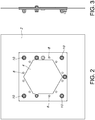
- panel 2 is a unit enclosure panel that separates the electrical components within it from the environment, including integrated panels, deadfronts, or transition plates.
- Aperture 20 in panel 2 is an opening through which the infrared scanner has a line of sight view of the electrical components.
- aperture 20 may be any shape and size to allow an infrared camera to have an unobstructed view of the electrical components in the electrical panel.
- Panel 2 also has a series of retention holes 14 surrounding the aperture 20.
- the retention holes 14 are configured to receive a portion of infrared transmissive polymer 4 and retention frame 6 as part of the half shear retention system that will keep the infrared transmissive polymer 4 in place. In a preferred embodiment, these retention holes 14 are located annually around aperture 20.
- the infrared transmissive polymer 4 will act as a window over the aperture 20.
- the infrared transmissive polymer 4 is a thin flexible sheet of polymer that allows the passage of infrared radiation through it. When positioned over aperture 20, the edges of the infrared transmissive polymer 4 extend beyond aperture 20 and overlap with panel 2.
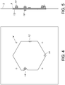
- Retention frame 6 is generally a flat piece of hard material, such as metal, having an opening in the interior that approximates the shape and size of aperture 20 and is referred to herein as frame opening 22.
- frame opening 22 is a symmetric, approximately hexagonal shape with cutouts to accommodate a captive retention bolt 18 (described below).
- retention frame 6 includes a series of half shear retainers 8 that surround frame opening 22.
- These half shear retainers 8 are dimple-like protrusions that extend from the plane of the retention frame 6. In a preferred embodiment, the half shear retainers 8 protrude beyond the plane to a distance of approximately half of the width of the retention frame 6.
- the half shear retainers 8 are positioned around the frame opening 22 such that each one lines up with a retention hole 14 in the panel 2 when they are placed against each other.
- the infrared transmissive polymer 4 also may include a series of holes, referred to as polymer holes 24, that are positioned in a corresponding pattern to the retention holes 14 in the retention frame 6. Each half shear retainer 8 is configured to pass through a corresponding polymer hole 24 and into a retention hole 14 in the panel 2 when the retention frame 6 and infrared transmissive polymer 4 are properly oriented and positioned together.
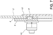
- the retention frame 6 and infrared transmissive polymer 4 can be positioned against panel 2, effectively sandwiching the infrared transmissive polymer 4 between retention frame 6 and panel 2.
- the assembly can then be secured by the use of hardware such as the retaining nuts 10 and retaining bolt 26.
- Retaining bolt 26 can be passed through holes in panel 2, infrared transmissive polymer 4, and retention frame 6.
- Retaining nut 10 can then be fastened onto the bolt, such that the retention frame 6 is secured against panel 2. It should be appreciated that retaining bolt 26 is short enough that it does not protrude very far into the electrical panel. This helps ensure that it does not come into contact with any energized electrical components.
- infrared transmissive polymer 4 With retention frame 6 securely fastened against panel 2, infrared transmissive polymer 4 is secured and is prevented from moving due to the series of half shear retainers 8 positioned around frame opening 22.
- the infrared transmissive polymer 4 would act as a window that infrared radiation can pass through while preventing contaminants from entering the electrical enclosure.
- the infrared transmissive polymer 4 would also prevent a user from inadvertently contacting electrical components housed within the electrical enclosure.
- a cover 12 that protects the transmissive infrared polymer 4 from being exposed to the environment, thus reducing the risk of it become damaged or dirty.
- cover 12 is approximately the same shape and slightly larger than aperture 20, such that it completely obscures aperture 20 when it is in a closed position. Cover 12 can swing in front of the aperture 20 due to it being affixed to the panel 2 through pivot point 16. The cover 12 is configured such that it can hook against captive retention bolt 18 and remain in a closed position.
Landscapes
- Physics & Mathematics (AREA)
- General Physics & Mathematics (AREA)
- Spectroscopy & Molecular Physics (AREA)
- Engineering & Computer Science (AREA)
- General Engineering & Computer Science (AREA)
- Mechanical Engineering (AREA)
- Microelectronics & Electronic Packaging (AREA)
- Photometry And Measurement Of Optical Pulse Characteristics (AREA)
Claims (15)
- Verfahren zum Befestigen eines Infrarot-Übertragungspolymers (4) an einem Feld (2) eines Schaltschranks, das Folgendes umfasst:a. Ausrichten von Halbscherhalterungen (8) auf einem Haltebügel (6) mit Löchern (24) in dem Infrarot-Übertragungspolymer (4) und Löchern (14) in dem Feld (2), wobei die Halbscherhalterungen (8) aus erhobenen Vorsprüngen (8) auf dem Haltebügel (6) bestehen;b. Platzieren des Infrarot-Übertragungspolymers (4) an dem Haltebügel (6);c. Ankoppeln des Haltebügels (6) an dem Feld (2); undd. Befestigen des Haltebügels (6) an dem Feld (2) mit Eisenwaren (26, 10).
- Verfahren nach Anspruch 1, wobei die Eisenwaren (26, 10) Bolzen (26) sind.
- Verfahren nach einem der vorstehenden Ansprüche, wobei die Halbscherhalterungen (8) über die Ebene des Haltebügels (6) um einen Abstand der halben Breite des Haltebügels (6) herausragen.
- Verfahren nach einem der vorstehenden Ansprüche, wobei der Schritt des Ankoppelns des Haltebügels (6) an dem Feld (2) ferner Folgendes umfasst:(1) Ausrichten von Bolzenlöchern des Infrarot-Übertragungspolymers (4) mit Bolzenlöchern des Feldes (2) und Bolzenlöchern des Haltebügels (6); und(2) Durchführen eines Bolzens (26) durch die ausgerichteten Bolzenlöcher des Haltebügels (6), ausgerichteten Bolzenlöcher des Infrarot-Übertragungspolymers (4), und ausgerichteten Bolzenlöcher des Feldes (2).
- Vorrichtung zum Befestigen eines Infrarot-Übertragungspolymers (4) an einem Feld (2) umfassend einen Haltebügel (6), wobei der Haltebügel (6) eine Bügelöffnung (22) umfasst und Vorsprünge (8) auf der Seite des Haltebügels (6) aufweist, die dem Feld (2) zugewandt ist, wobei die Vorsprünge (8) den entsprechenden Löchern (24) in dem Infrarot-Übertragungspolymer (4) und Löchern (14) in dem Feld (2) entsprechen,
wobei das Infrarot-Übertragungspolymer (4) zwischen dem Haltebügel (6) und dem Feld (2) positioniert ist und wobei der Haltebügel (6) so konfiguriert ist, dass er an dem Feld (2) mit Eisenwaren (26, 10) befestigt ist. - Vorrichtung nach Anspruch 5, wobei das Infrarot-Übertragungspolymer (4) Löcher (24) zur Aufnahme jedes der Vorsprünge (8) aufweist.
- Vorrichtung nach Anspruch 5 oder 6, die ferner eine Abdeckung (12) aufweist, die so konfiguriert ist, dass sie an dem Feld (2) befestigt wird und das Infrarot-Übertragungspolymer (4) verbirgt.
- Vorrichtung nach Anspruch 7, wobei die Abdeckung (12) an dem Feld (2) mit einem Scharnier befestigt ist.
- Vorrichtung nach einem der Ansprüche 5-8, wobei die Vorsprünge (8) Halbscherhalterungen (8) sind.
- Vorrichtung nach einem der Ansprüche 5-9, wobei sich die Vorsprünge (8) über einen Abstand der halben Breite des Haltebügels (6) erstrecken.
- Vorrichtung nach einem der Ansprüche 5-10, wobei der Haltebügel (6) Bolzenlöcher zur Aufnahme eines Bolzens (26) zum Befestigen des Haltebügels (6) an dem Feld (2) aufweist.
- Vorrichtung nach Anspruch 11, wobei das Infrarot-Übertragungspolymer (4) Bolzenlöcher aufweist, die in ihrer Position den Bolzenlöchern des Haltebügels (6) entsprechen.
- Verfahren zum Befestigen eines Infrarot-Übertragungspolymers (4) an einem Feld (2) eines Schaltschranks, das Folgendes umfasst:a. Positionieren eines Haltebügels (6) mit Halbscherhalterungen (8) derart, dass die Halbscherhalterungen (8) auf entsprechende Löcher (14) in dem elektrischen Feld (2) und entsprechende Löcher (24) in dem Infrarot-Übertragungspolymer (4) ausgerichtet sind; und wobei das Infrarot-Übertragungspolymer (4) zwischen dem Haltebügel (6) und dem elektrischen Feld (2) positioniert ist;b. Drücken des Haltebügels (6) gegen das Feld (2); undc. Befestigen des Haltebügels (6) gegen das Feld (2) mit Eisenwaren (26, 10).
- Verfahren nach Anspruch 13, das ferner den Schritt eines Einführens der Halbscherhalterungen (8) durch die entsprechenden Löcher (24) des eingeführten Infrarot-Übertragungspolymers (4) umfasst.
- Verfahren nach Anspruch 13 oder 14, wobei der Schritt des Befestigens des Haltebügels (6) gegen das Feld (2) Folgendes umfasst:(1) Platzieren eines Bolzens (26) durch ein Loch in dem Haltebügel (6);(2) Platzieren des Bolzens (26) durch ein Loch in dem Infrarot-Übertragungspolymer (4);(3) Platzieren des Bolzens (26) durch ein Loch in dem Feld (2); und(4) Befestigen einer Mutter (10) auf der gegenüberliegenden Seite des Feldes (2) an dem Bolzen (26).
Applications Claiming Priority (1)
| Application Number | Priority Date | Filing Date | Title |
|---|---|---|---|
| US201161558705P | 2011-11-11 | 2011-11-11 |
Publications (3)
| Publication Number | Publication Date |
|---|---|
| EP2602803A2 EP2602803A2 (de) | 2013-06-12 |
| EP2602803A3 EP2602803A3 (de) | 2016-08-03 |
| EP2602803B1 true EP2602803B1 (de) | 2017-09-13 |
Family
ID=47678453
Family Applications (1)
| Application Number | Title | Priority Date | Filing Date |
|---|---|---|---|
| EP12192284.3A Not-in-force EP2602803B1 (de) | 2011-11-11 | 2012-11-12 | Infrarot-Scananschluss |
Country Status (3)
| Country | Link |
|---|---|
| US (2) | US9044832B2 (de) |
| EP (1) | EP2602803B1 (de) |
| CA (1) | CA2794870C (de) |
Families Citing this family (10)
| Publication number | Priority date | Publication date | Assignee | Title |
|---|---|---|---|---|
| USD727326S1 (en) * | 2011-11-11 | 2015-04-21 | Thomas & Betts International, Llc | Infrared scanning port assembly |
| WO2015065376A1 (en) * | 2012-10-30 | 2015-05-07 | Rohrer Timothy | Inspection window |
| WO2017120425A1 (en) * | 2016-01-08 | 2017-07-13 | Iriss, Inc. | Replacement panels for electrical distribution cabinets for the monitoring of targeted components and connections |
| EP3615952B1 (de) | 2017-04-25 | 2024-11-27 | Iriss Holdings, Inc. | Paneel zur hörbaren überwachung elektrischer bauteile und zur erfassung elektrischer fehler |
| CN109391075A (zh) * | 2017-08-10 | 2019-02-26 | 广东核电合营有限公司 | 一种核电厂发电机出线仓室及其温度监测方法 |
| US10474613B1 (en) | 2017-12-22 | 2019-11-12 | Fend, Inc. | One-way data transfer device with onboard system detection |
| EP3729773B1 (de) * | 2017-12-22 | 2021-11-03 | Fend Incorporated | Einweg-datenübertragungsvorrichtung mit integrierter systemerkennung |
| AU2020101000A4 (en) * | 2019-06-12 | 2020-07-16 | Woodside Energy Technologies Pty Ltd | A junction box lid and a junction box incorporating the lid |
| US11153345B1 (en) * | 2020-05-20 | 2021-10-19 | Fend Incorporated | One-way transfer device with secure reverse channel |
| US11709970B1 (en) | 2022-12-19 | 2023-07-25 | Fend Incorporated | One-way communication data diode on a chip |
Family Cites Families (25)
| Publication number | Priority date | Publication date | Assignee | Title |
|---|---|---|---|---|
| US1547142A (en) | 1923-02-06 | 1925-07-21 | Bausch & Lomb | Lens frame |
| US3387080A (en) | 1966-07-25 | 1968-06-04 | Burndy Corp | Splice connector with locking insert |
| EP0137930A3 (de) | 1983-09-14 | 1986-07-30 | Dornier Gmbh | Schutzüberzug oder Fenster |
| JPH02208601A (ja) | 1989-02-08 | 1990-08-20 | Seiko Instr Inc | 光学用窓材及びその製造方法 |
| US5481400A (en) | 1993-11-09 | 1996-01-02 | Hughes Aircraft Company | Survivable window grids |
| US5493126A (en) | 1995-02-27 | 1996-02-20 | Hughes Aircraft Company | LWIR-transmitting windows |
| FR2743153B1 (fr) | 1995-12-29 | 1998-03-27 | Brun Michel | Hublot de visee, notamment pour controle de la temperature d'objets par thermographie infrarouge |
| US5776612A (en) | 1996-02-21 | 1998-07-07 | Exotic Materials Inc. | Window that transmits light energy and selectively absorbs microwave energy |
| US5735168A (en) * | 1996-04-23 | 1998-04-07 | Harrison; Jack | Animal feeder sight glass device |
| US5986211A (en) * | 1998-02-19 | 1999-11-16 | Square D Company | Viewing window construction for a disconnect switch |
| EP1173651B1 (de) * | 2000-02-29 | 2003-12-17 | Cockburn Thermal Imaging Limited | Thermofenster und Einbauverfahren hierfür |
| US6635892B2 (en) * | 2002-01-24 | 2003-10-21 | Pei Electronics, Inc. | Compact integrated infrared scene projector |
| US7079334B2 (en) | 2003-02-04 | 2006-07-18 | Holliday Graham R | Infrared sight glass for aftermarket fitment |
| US7286309B2 (en) | 2004-01-28 | 2007-10-23 | Holliday Graham R | Infrared sight glass for aftermarket fitment |
| GB2447888B (en) * | 2007-03-20 | 2010-03-31 | Martin Robinson | Infrared window assembly |
| GB2447666B (en) | 2007-03-20 | 2010-03-31 | Martin Robinson | Infrared window assembly with covers |
| US8104911B2 (en) * | 2007-09-28 | 2012-01-31 | Apple Inc. | Display system with distributed LED backlight |
| US7687777B2 (en) | 2007-10-16 | 2010-03-30 | Shop Vac Corporation | Aperture assembly for use with a photosensor system and a securing mechanism for the aperture assembly |
| US8023818B2 (en) * | 2008-07-24 | 2011-09-20 | Fluke Corporation | Articulating infrared window |
| DE112009004508B4 (de) * | 2009-03-19 | 2013-07-04 | Mitsubishi Electric Corp. | An einer Bedienplatte montierte Anordnung |
| TWI402575B (zh) * | 2009-12-18 | 2013-07-21 | Au Optronics Corp | 具片狀光學元件定位效果之背光模組及顯示裝置 |
| KR20120030802A (ko) * | 2010-09-20 | 2012-03-29 | 삼성전자주식회사 | 액정표시모듈 및 이를 갖는 액정표시장치 |
| CA2796997C (en) * | 2011-06-11 | 2016-05-10 | Dirtt Environmental Solutions, Ltd. | Modular wall nesting system |
| GB201121818D0 (en) * | 2011-12-19 | 2012-02-01 | Certification Information Ltd | Apparatus and method |
| CN104076869A (zh) * | 2013-03-29 | 2014-10-01 | 鸿富锦精密工业(深圳)有限公司 | 摄像头旋转结构 |
-
2012
- 2012-11-09 US US13/673,621 patent/US9044832B2/en not_active Expired - Fee Related
- 2012-11-09 CA CA2794870A patent/CA2794870C/en not_active Expired - Fee Related
- 2012-11-12 EP EP12192284.3A patent/EP2602803B1/de not_active Not-in-force
-
2015
- 2015-04-21 US US14/692,160 patent/US10111351B2/en not_active Expired - Fee Related
Non-Patent Citations (1)
| Title |
|---|
| None * |
Also Published As
| Publication number | Publication date |
|---|---|
| US20130117995A1 (en) | 2013-05-16 |
| EP2602803A2 (de) | 2013-06-12 |
| US20150230354A1 (en) | 2015-08-13 |
| US9044832B2 (en) | 2015-06-02 |
| CA2794870A1 (en) | 2013-05-11 |
| US10111351B2 (en) | 2018-10-23 |
| EP2602803A3 (de) | 2016-08-03 |
| CA2794870C (en) | 2017-06-27 |
Similar Documents
| Publication | Publication Date | Title |
|---|---|---|
| EP2602803B1 (de) | Infrarot-Scananschluss | |
| US8164827B2 (en) | Infrared window assembly | |
| US20130135804A1 (en) | Frame housing and display device | |
| US20100014152A1 (en) | Infrared window assembly with internal and external cover | |
| US20170075160A1 (en) | Surface frame for display module, display module and display device | |
| US20200389603A1 (en) | Multi-lens camera | |
| RU2637835C2 (ru) | Система лучевой визуализации | |
| US20180324984A1 (en) | Installation tool for flexible elements | |
| CN115485506A (zh) | 用于烤箱设备的门组件 | |
| US10732421B2 (en) | Bus duct with a curved viewing window assembly | |
| EP3450854B1 (de) | Garofen mit einer reflexionsabschirmung und einer kamera | |
| US20190173267A1 (en) | Replacement panels for electrical distribution cabinets for the monitoring of targeted components and connections | |
| US10613361B2 (en) | Display device | |
| US20130229780A1 (en) | Patch panel and method of facilitating access to rear ports of a component | |
| EP3450853B1 (de) | Backofen mit einer kameraanordnung | |
| EP3958414B1 (de) | Schaltschrank mit detektor für temperaturanomalien | |
| EP1173651B1 (de) | Thermofenster und Einbauverfahren hierfür | |
| TW201630504A (zh) | 攜帶型電子機器 | |
| US20110115588A1 (en) | Magnetic Attachment of Detector Modules enabling front side removal | |
| KR100661287B1 (ko) | 카메라 모듈 | |
| KR101424267B1 (ko) | 디스플레이 기기의 커버 및 상기 커버의 조립 방법 | |
| CN220653665U (zh) | 一种拼装式机壳 | |
| KR200461812Y1 (ko) | 보안기용 서포터 세트 | |
| JP2018190879A (ja) | ユニットの取付構造 | |
| RU72781U1 (ru) | Устройство для защиты плоскопанельных дисплеев и телевизоров от механических повреждений |
Legal Events
| Date | Code | Title | Description |
|---|---|---|---|
| PUAI | Public reference made under article 153(3) epc to a published international application that has entered the european phase |
Free format text: ORIGINAL CODE: 0009012 |
|
| AK | Designated contracting states |
Kind code of ref document: A2 Designated state(s): AL AT BE BG CH CY CZ DE DK EE ES FI FR GB GR HR HU IE IS IT LI LT LU LV MC MK MT NL NO PL PT RO RS SE SI SK SM TR |
|
| AX | Request for extension of the european patent |
Extension state: BA ME |
|
| PUAL | Search report despatched |
Free format text: ORIGINAL CODE: 0009013 |
|
| AK | Designated contracting states |
Kind code of ref document: A3 Designated state(s): AL AT BE BG CH CY CZ DE DK EE ES FI FR GB GR HR HU IE IS IT LI LT LU LV MC MK MT NL NO PL PT RO RS SE SI SK SM TR |
|
| AX | Request for extension of the european patent |
Extension state: BA ME |
|
| RIC1 | Information provided on ipc code assigned before grant |
Ipc: G01J 5/08 20060101ALI20160630BHEP Ipc: H05K 5/02 20060101ALI20160630BHEP Ipc: B23P 11/00 20060101ALI20160630BHEP Ipc: H01H 1/00 20060101AFI20160630BHEP Ipc: F16B 33/00 20060101ALI20160630BHEP Ipc: H02B 1/30 20060101ALI20160630BHEP |
|
| 17P | Request for examination filed |
Effective date: 20170203 |
|
| RBV | Designated contracting states (corrected) |
Designated state(s): AL AT BE BG CH CY CZ DE DK EE ES FI FR GB GR HR HU IE IS IT LI LT LU LV MC MK MT NL NO PL PT RO RS SE SI SK SM TR |
|
| GRAP | Despatch of communication of intention to grant a patent |
Free format text: ORIGINAL CODE: EPIDOSNIGR1 |
|
| RIC1 | Information provided on ipc code assigned before grant |
Ipc: G01J 5/08 20060101ALI20170323BHEP Ipc: F16B 33/00 20060101ALI20170323BHEP Ipc: H02B 1/30 20060101ALI20170323BHEP Ipc: H02B 3/00 20060101ALI20170323BHEP Ipc: H01H 1/00 20060101AFI20170323BHEP Ipc: B23P 11/00 20060101ALI20170323BHEP Ipc: H05K 5/02 20060101ALI20170323BHEP |
|
| INTG | Intention to grant announced |
Effective date: 20170411 |
|
| GRAS | Grant fee paid |
Free format text: ORIGINAL CODE: EPIDOSNIGR3 |
|
| GRAA | (expected) grant |
Free format text: ORIGINAL CODE: 0009210 |
|
| AK | Designated contracting states |
Kind code of ref document: B1 Designated state(s): AL AT BE BG CH CY CZ DE DK EE ES FI FR GB GR HR HU IE IS IT LI LT LU LV MC MK MT NL NO PL PT RO RS SE SI SK SM TR |
|
| REG | Reference to a national code |
Ref country code: GB Ref legal event code: FG4D |
|
| REG | Reference to a national code |
Ref country code: CH Ref legal event code: EP |
|
| REG | Reference to a national code |
Ref country code: IE Ref legal event code: FG4D |
|
| REG | Reference to a national code |
Ref country code: AT Ref legal event code: REF Ref document number: 928899 Country of ref document: AT Kind code of ref document: T Effective date: 20171015 |
|
| REG | Reference to a national code |
Ref country code: DE Ref legal event code: R096 Ref document number: 602012037225 Country of ref document: DE |
|
| REG | Reference to a national code |
Ref country code: NL Ref legal event code: MP Effective date: 20170913 |
|
| REG | Reference to a national code |
Ref country code: LT Ref legal event code: MG4D |
|
| PG25 | Lapsed in a contracting state [announced via postgrant information from national office to epo] |
Ref country code: LT Free format text: LAPSE BECAUSE OF FAILURE TO SUBMIT A TRANSLATION OF THE DESCRIPTION OR TO PAY THE FEE WITHIN THE PRESCRIBED TIME-LIMIT Effective date: 20170913 Ref country code: FI Free format text: LAPSE BECAUSE OF FAILURE TO SUBMIT A TRANSLATION OF THE DESCRIPTION OR TO PAY THE FEE WITHIN THE PRESCRIBED TIME-LIMIT Effective date: 20170913 Ref country code: NO Free format text: LAPSE BECAUSE OF FAILURE TO SUBMIT A TRANSLATION OF THE DESCRIPTION OR TO PAY THE FEE WITHIN THE PRESCRIBED TIME-LIMIT Effective date: 20171213 Ref country code: SE Free format text: LAPSE BECAUSE OF FAILURE TO SUBMIT A TRANSLATION OF THE DESCRIPTION OR TO PAY THE FEE WITHIN THE PRESCRIBED TIME-LIMIT Effective date: 20170913 Ref country code: HR Free format text: LAPSE BECAUSE OF FAILURE TO SUBMIT A TRANSLATION OF THE DESCRIPTION OR TO PAY THE FEE WITHIN THE PRESCRIBED TIME-LIMIT Effective date: 20170913 |
|
| REG | Reference to a national code |
Ref country code: AT Ref legal event code: MK05 Ref document number: 928899 Country of ref document: AT Kind code of ref document: T Effective date: 20170913 |
|
| PG25 | Lapsed in a contracting state [announced via postgrant information from national office to epo] |
Ref country code: RS Free format text: LAPSE BECAUSE OF FAILURE TO SUBMIT A TRANSLATION OF THE DESCRIPTION OR TO PAY THE FEE WITHIN THE PRESCRIBED TIME-LIMIT Effective date: 20170913 Ref country code: GR Free format text: LAPSE BECAUSE OF FAILURE TO SUBMIT A TRANSLATION OF THE DESCRIPTION OR TO PAY THE FEE WITHIN THE PRESCRIBED TIME-LIMIT Effective date: 20171214 Ref country code: BG Free format text: LAPSE BECAUSE OF FAILURE TO SUBMIT A TRANSLATION OF THE DESCRIPTION OR TO PAY THE FEE WITHIN THE PRESCRIBED TIME-LIMIT Effective date: 20171213 Ref country code: LV Free format text: LAPSE BECAUSE OF FAILURE TO SUBMIT A TRANSLATION OF THE DESCRIPTION OR TO PAY THE FEE WITHIN THE PRESCRIBED TIME-LIMIT Effective date: 20170913 Ref country code: ES Free format text: LAPSE BECAUSE OF FAILURE TO SUBMIT A TRANSLATION OF THE DESCRIPTION OR TO PAY THE FEE WITHIN THE PRESCRIBED TIME-LIMIT Effective date: 20170913 |
|
| PG25 | Lapsed in a contracting state [announced via postgrant information from national office to epo] |
Ref country code: NL Free format text: LAPSE BECAUSE OF FAILURE TO SUBMIT A TRANSLATION OF THE DESCRIPTION OR TO PAY THE FEE WITHIN THE PRESCRIBED TIME-LIMIT Effective date: 20170913 |
|
| PG25 | Lapsed in a contracting state [announced via postgrant information from national office to epo] |
Ref country code: RO Free format text: LAPSE BECAUSE OF FAILURE TO SUBMIT A TRANSLATION OF THE DESCRIPTION OR TO PAY THE FEE WITHIN THE PRESCRIBED TIME-LIMIT Effective date: 20170913 Ref country code: PL Free format text: LAPSE BECAUSE OF FAILURE TO SUBMIT A TRANSLATION OF THE DESCRIPTION OR TO PAY THE FEE WITHIN THE PRESCRIBED TIME-LIMIT Effective date: 20170913 Ref country code: CZ Free format text: LAPSE BECAUSE OF FAILURE TO SUBMIT A TRANSLATION OF THE DESCRIPTION OR TO PAY THE FEE WITHIN THE PRESCRIBED TIME-LIMIT Effective date: 20170913 |
|
| PG25 | Lapsed in a contracting state [announced via postgrant information from national office to epo] |
Ref country code: IT Free format text: LAPSE BECAUSE OF FAILURE TO SUBMIT A TRANSLATION OF THE DESCRIPTION OR TO PAY THE FEE WITHIN THE PRESCRIBED TIME-LIMIT Effective date: 20170913 Ref country code: SK Free format text: LAPSE BECAUSE OF FAILURE TO SUBMIT A TRANSLATION OF THE DESCRIPTION OR TO PAY THE FEE WITHIN THE PRESCRIBED TIME-LIMIT Effective date: 20170913 Ref country code: SM Free format text: LAPSE BECAUSE OF FAILURE TO SUBMIT A TRANSLATION OF THE DESCRIPTION OR TO PAY THE FEE WITHIN THE PRESCRIBED TIME-LIMIT Effective date: 20170913 Ref country code: EE Free format text: LAPSE BECAUSE OF FAILURE TO SUBMIT A TRANSLATION OF THE DESCRIPTION OR TO PAY THE FEE WITHIN THE PRESCRIBED TIME-LIMIT Effective date: 20170913 Ref country code: AT Free format text: LAPSE BECAUSE OF FAILURE TO SUBMIT A TRANSLATION OF THE DESCRIPTION OR TO PAY THE FEE WITHIN THE PRESCRIBED TIME-LIMIT Effective date: 20170913 Ref country code: IS Free format text: LAPSE BECAUSE OF FAILURE TO SUBMIT A TRANSLATION OF THE DESCRIPTION OR TO PAY THE FEE WITHIN THE PRESCRIBED TIME-LIMIT Effective date: 20180113 |
|
| REG | Reference to a national code |
Ref country code: DE Ref legal event code: R119 Ref document number: 602012037225 Country of ref document: DE |
|
| PG25 | Lapsed in a contracting state [announced via postgrant information from national office to epo] |
Ref country code: MC Free format text: LAPSE BECAUSE OF FAILURE TO SUBMIT A TRANSLATION OF THE DESCRIPTION OR TO PAY THE FEE WITHIN THE PRESCRIBED TIME-LIMIT Effective date: 20170913 |
|
| PLBE | No opposition filed within time limit |
Free format text: ORIGINAL CODE: 0009261 |
|
| STAA | Information on the status of an ep patent application or granted ep patent |
Free format text: STATUS: NO OPPOSITION FILED WITHIN TIME LIMIT |
|
| PG25 | Lapsed in a contracting state [announced via postgrant information from national office to epo] |
Ref country code: LI Free format text: LAPSE BECAUSE OF NON-PAYMENT OF DUE FEES Effective date: 20171130 Ref country code: DK Free format text: LAPSE BECAUSE OF FAILURE TO SUBMIT A TRANSLATION OF THE DESCRIPTION OR TO PAY THE FEE WITHIN THE PRESCRIBED TIME-LIMIT Effective date: 20170913 Ref country code: CH Free format text: LAPSE BECAUSE OF NON-PAYMENT OF DUE FEES Effective date: 20171130 |
|
| 26N | No opposition filed |
Effective date: 20180614 |
|
| GBPC | Gb: european patent ceased through non-payment of renewal fee |
Effective date: 20171213 |
|
| PG25 | Lapsed in a contracting state [announced via postgrant information from national office to epo] |
Ref country code: LU Free format text: LAPSE BECAUSE OF NON-PAYMENT OF DUE FEES Effective date: 20171112 |
|
| REG | Reference to a national code |
Ref country code: FR Ref legal event code: ST Effective date: 20180731 Ref country code: BE Ref legal event code: MM Effective date: 20171130 |
|
| REG | Reference to a national code |
Ref country code: IE Ref legal event code: MM4A |
|
| PG25 | Lapsed in a contracting state [announced via postgrant information from national office to epo] |
Ref country code: MT Free format text: LAPSE BECAUSE OF NON-PAYMENT OF DUE FEES Effective date: 20171112 |
|
| PG25 | Lapsed in a contracting state [announced via postgrant information from national office to epo] |
Ref country code: DE Free format text: LAPSE BECAUSE OF NON-PAYMENT OF DUE FEES Effective date: 20180602 Ref country code: FR Free format text: LAPSE BECAUSE OF NON-PAYMENT OF DUE FEES Effective date: 20171130 Ref country code: IE Free format text: LAPSE BECAUSE OF NON-PAYMENT OF DUE FEES Effective date: 20171112 |
|
| PG25 | Lapsed in a contracting state [announced via postgrant information from national office to epo] |
Ref country code: SI Free format text: LAPSE BECAUSE OF FAILURE TO SUBMIT A TRANSLATION OF THE DESCRIPTION OR TO PAY THE FEE WITHIN THE PRESCRIBED TIME-LIMIT Effective date: 20170913 Ref country code: GB Free format text: LAPSE BECAUSE OF NON-PAYMENT OF DUE FEES Effective date: 20171213 Ref country code: BE Free format text: LAPSE BECAUSE OF NON-PAYMENT OF DUE FEES Effective date: 20171130 |
|
| PG25 | Lapsed in a contracting state [announced via postgrant information from national office to epo] |
Ref country code: HU Free format text: LAPSE BECAUSE OF FAILURE TO SUBMIT A TRANSLATION OF THE DESCRIPTION OR TO PAY THE FEE WITHIN THE PRESCRIBED TIME-LIMIT; INVALID AB INITIO Effective date: 20121112 |
|
| PG25 | Lapsed in a contracting state [announced via postgrant information from national office to epo] |
Ref country code: CY Free format text: LAPSE BECAUSE OF NON-PAYMENT OF DUE FEES Effective date: 20170913 |
|
| PG25 | Lapsed in a contracting state [announced via postgrant information from national office to epo] |
Ref country code: MK Free format text: LAPSE BECAUSE OF FAILURE TO SUBMIT A TRANSLATION OF THE DESCRIPTION OR TO PAY THE FEE WITHIN THE PRESCRIBED TIME-LIMIT Effective date: 20170913 |
|
| PG25 | Lapsed in a contracting state [announced via postgrant information from national office to epo] |
Ref country code: TR Free format text: LAPSE BECAUSE OF FAILURE TO SUBMIT A TRANSLATION OF THE DESCRIPTION OR TO PAY THE FEE WITHIN THE PRESCRIBED TIME-LIMIT Effective date: 20170913 |
|
| PG25 | Lapsed in a contracting state [announced via postgrant information from national office to epo] |
Ref country code: PT Free format text: LAPSE BECAUSE OF FAILURE TO SUBMIT A TRANSLATION OF THE DESCRIPTION OR TO PAY THE FEE WITHIN THE PRESCRIBED TIME-LIMIT Effective date: 20170913 |
|
| PG25 | Lapsed in a contracting state [announced via postgrant information from national office to epo] |
Ref country code: AL Free format text: LAPSE BECAUSE OF FAILURE TO SUBMIT A TRANSLATION OF THE DESCRIPTION OR TO PAY THE FEE WITHIN THE PRESCRIBED TIME-LIMIT Effective date: 20170913 |