EP2602888A2 - Lösbare Sperrvorrichtung mit Winkeleinstellbarkeit - Google Patents
Lösbare Sperrvorrichtung mit Winkeleinstellbarkeit Download PDFInfo
- Publication number
- EP2602888A2 EP2602888A2 EP12195530.6A EP12195530A EP2602888A2 EP 2602888 A2 EP2602888 A2 EP 2602888A2 EP 12195530 A EP12195530 A EP 12195530A EP 2602888 A2 EP2602888 A2 EP 2602888A2
- Authority
- EP
- European Patent Office
- Prior art keywords
- assembly
- insertion member
- receiving member
- engagement
- axis
- Prior art date
- Legal status (The legal status is an assumption and is not a legal conclusion. Google has not performed a legal analysis and makes no representation as to the accuracy of the status listed.)
- Granted
Links
- 238000003780 insertion Methods 0.000 claims abstract description 80
- 230000037431 insertion Effects 0.000 claims abstract description 80
- 230000000284 resting effect Effects 0.000 claims abstract description 6
- 230000000295 complement effect Effects 0.000 claims description 11
- 238000009434 installation Methods 0.000 claims description 7
- 239000012811 non-conductive material Substances 0.000 claims description 4
- 239000004020 conductor Substances 0.000 claims description 2
- 229910052751 metal Inorganic materials 0.000 description 6
- 239000002184 metal Substances 0.000 description 5
- 238000010276 construction Methods 0.000 description 4
- 239000000463 material Substances 0.000 description 3
- 238000012986 modification Methods 0.000 description 2
- 230000004048 modification Effects 0.000 description 2
- 238000013461 design Methods 0.000 description 1
- 238000010586 diagram Methods 0.000 description 1
- 239000000835 fiber Substances 0.000 description 1
- 238000000034 method Methods 0.000 description 1
- 238000013519 translation Methods 0.000 description 1
Images


Classifications
-
- H—ELECTRICITY
- H02—GENERATION; CONVERSION OR DISTRIBUTION OF ELECTRIC POWER
- H02G—INSTALLATION OF ELECTRIC CABLES OR LINES, OR OF COMBINED OPTICAL AND ELECTRIC CABLES OR LINES
- H02G3/00—Installations of electric cables or lines or protective tubing therefor in or on buildings, equivalent structures or vehicles
- H02G3/02—Details
- H02G3/08—Distribution boxes; Connection or junction boxes
- H02G3/12—Distribution boxes; Connection or junction boxes for flush mounting
- H02G3/123—Distribution boxes; Connection or junction boxes for flush mounting in thin walls
Definitions
- the invention generally relates to mounting of electrical boxes on a surface such as wall.
- the invention relates to releasable snap locking with angular adjustability to install or mount devices to boxes.
- the boxes may be wall mounted electrical boxes.
- the electrical boxes are mounted on a resting surface such as wall. In the event of oblique mounting of the electrical box, the final assembly can still be aligned straight if the electrical box or any fixing components of the electrical box offer angular adjustability mechanism.
- the conventional electrical boxes include key slots and screws to provide such angular adjustability.
- the main object of the present invention is to provide an electrical box with an integral angular adjustability mechanism, which obviates the use of screws.
- Another object of the present invention is to provide an electrical box with an integral angular adjustability mechanism, which eliminates the use of any metal parts.
- Another object of the present invention is to provide an electrical box with an integral angular adjustability mechanism, which eliminates use of any external or additional parts.
- Another object of the present invention is to provide an electrical box with an integral angular adjustability mechanism, which provides quicker installation and dismantling of the assembly.
- Yet another object of the present invention is to provide an electrical box with an integral angular adjustability mechanism, which provides tool-less installation and dismantling of the assembly.
- the design also may be made for tooled removal and assembly.
- Further object of the present invention is to provide an electrical box with an integral angular adjustability mechanism, which provides wide range of flexibility for angular alignment.
- the invention discloses an assembly of an insertion member and a receiving member configured to be engaged by screw-less, snap-in installation.
- the insertion member includes one or more bracket extended from a plane of the insertion member, a lower end of the one or more bracket including one or more tooth unit, and at least one guiding unit for securely engaging the insertion member with the receiving member.
- the receiving member includes one or more opening for complementarily engaging the one or more bracket of the insertion member, one or more resting surface including plurality of slots for engaging the one or more tooth unit of the one or more bracket, and at least one recess for receiving the at least one guiding unit.
- a first engagement of the assembly restricts linear movement of the insertion member along a first axis, a second axis and a third axis, and rotation about the first axis and the second axis. Further, a second engagement of the assembly restricts rotation about the third axis thereby securely engaging the insertion member with the receiving member.
- the receiving member further includes one or more holding member for engaging the one or more bracket temporarily in the first engagement of the assembly, the first engagement allowing angular adjustment of the insertion member with respect to the receiving member.
- at least one recess of the receiving member comprises a dimension to allow the angular adjustment of the at least one guiding unit of the insertion member.
- the assembly includes slot-tooth mechanism integral to the assembly for the angular adjustment of the insertion member with respect to the receiving member in the first engagement.
- the insertion member is pre-assembled in the receiving member in the first engagement of the assembly.
- the receiving member and the insertion member are made of electrically non-conductive materials or electrically conductive materials.
- the insertion member has a rectangular or circular or semi-circular or polygonal shape and the receiving member has a complementary rectangular or circular or semi-circular or polygonal aperture.
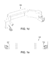
- FIG. 1a-1e schematically illustrates the construction of such a receiving member 100 of an assembly according to one embodiment of the present invention.
- the receiving member 100 may include an electrical box.
- the receiving member 100 may be made of any material depending on its application. However, in the present embodiment, it is made of an electrically non-conductive material such as plastic.
- the receiving member 100 may have any shape such as circular, semi-circular, rectangular, polygonal and so forth.
- the two sides of the receiving member 100 may include two complementary openings 102.
- the complementary openings 102 facilitate snap-in engagement mechanism.
- the receiving member 100 includes two resting surfaces 104 for accommodating two brackets.
- the resting surface 104 may have plurality of slots 106 made on them.
- the slots 106 ensure secure assembly of the receiving member 100 with the insertion member.
- the slots 106 may have various shapes such as oval, round, gear teeth and so forth. Further, the pitch between the slots may vary as per application need.
- the receiving member 100 further includes four recesses 108 placed at the four corners.
- the recesses 108 may also facilitate in secure mounting of the assembly.
- the receiving member further includes two holding members 110.
- the holding members110 enables to achieve two stage engagements in the present assembly.
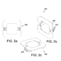
- FIG. 2a-2g schematically illustrates the construction of the insertion member 200 of an assembly according to one embodiment of the present invention.
- the insertion member 200 may include a fixing frame or a technical frame.
- an aesthetic frame may cover the fixing frame for aesthetic appeal.
- the insertion member 200 may be made of any material which provides required flexibility to deform in multi stage engagement mechanism.
- the insertion member 200 may be made of electrically non-conductive material such as plastic, fiber and so forth.
- the insertion member 200 may have a shape complementarily matching the shape of the receiving member 100.
- the insertion member 200 may include includes two brackets 202.
- the brackets 202 extend from the plane of the insertion member 200.
- the lower end of the brackets 202 further includes plurality of teeth unit 204.
- the teeth unit 204 seat on the slots 106 of the receiving member 100.
- the teeth unit 204 may include various complementary shapes to index to the slots 106 of various shapes such as oval, round, gear teeth and so forth.
- the insertion member 200 may include plurality of guiding units.
- the insertion unit includes four guiding units 206 placed at the four corners of the insertion member 200. In the assembled state, the guiding units 206 get engaged with the recesses 108 of the receiving unit 100.
- FIG. 3-11 illustrates in detail the various stages of engagement of the insertion member 200 with the receiving member 100.
- FIG. 3a-3d schematically illustrates the perspective views of the relative position of the receiving member 100 and the insertion member 200 before assembly according to one embodiment of the present invention.
- the receiving member 100 may be installed on a surface such as a wall, floor, roof and so forth.
- the complementary opening 102 may remain exposed from an aperture made in such surface for receiving the brackets 202.
- FIG. 3a and FIG. 3c illustrate such an assembly installed in a wall.
- FIG. 3b and FIG. 3d illustrate such snap-in assembly without wall structure. As the assembly uses a snap-in mechanism, therefore no screw is required for the assembly. This may be apparent from the diagrams FIG. 3a-3d .
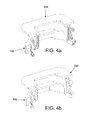
- FIG. 4a-4d schematically illustrates the cross-sectional views of the receiving member 100 and the insertion member 200 before assembly according to one embodiment of the present invention. Further, FIG. 4a and FIG. 4c illustrate the cross sectional views with the receiving member 100 installed in the wall. FIG. 4b and FIG. 4d illustrate the assembly without the wall.
- FIG. 5a-5d schematically illustrates the cross-sectional side views the receiving member 100 and the insertion member 200 before assembly according to one embodiment of the present invention. Further, FIG. 5a and FIG. 5c show the cross-sectional side views with the wall.
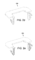
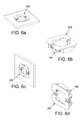
- FIG. 6a-6d schematically illustrates the perspective views of the receiving member 100 and the insertion member 200 in a first engagement of the assembly according to one embodiment of the present invention.
- FIG. 6a and FIG. 6c show the assembly with the wall.
- the brackets 202 of the insertion member 200 get inserted within the complementary openings 102 of the receiving unit 100 and temporarily rest on the holding members 110.
- the movement of the insertion member 200 is restricted by five degrees of freedom with respect to the receiving member 100.
- the five degrees of freedom include translation along X, Y, Z axis, and rotation about X, and Y axis. Only rotation about Z axis is permitted at this stage.
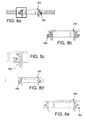
- FIG. 7a-7e schematically illustrates the cross-sectional views of the receiving member 100 and the insertion member 200 in a first engagement of the assembly according to one embodiment of the present invention. Further, FIG. 7a and FIG. 7c illustrate the assembly in the first engagement with the wall. FIG. 7e illustrates an exploded view of one of the brackets 202 inserted within one of the complementary openings 102, wherein the brackets 202 rest on the holding members 110.
- FIG 8a-8e schematically illustrates the cross-sectional side views of the receiving member 100 and the insertion member 200 in a first engagement of the assembly according to one embodiment of the present invention.
- FIG. 8a and FIG. 8c illustrate the assembly in the first engagement with the wall.
- FIG. 8e illustrates an exploded cross-sectional view of one of the brackets 202 inserted within one of the complementary openings 102, wherein the brackets 202 rest on the holding members 110.
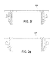
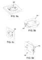
- FIG. 9a-9d schematically illustrates the perspective views of the receiving member 100 and the insertion member 200 in a second engagement of the assembly according to one embodiment of the present invention.
- FIG. 9a and FIG. 9c illustrate the assembly in the second engagement with the receiving member 100 installed in the wall.
- the angular position of the insertion member 200 may be adjusted with respect to the receiving member 100, before the second engagement.
- the receiving member 100 is installed oblique in the wall, by adjusting the angular position of the insertion member 200 with respect to the receiving member 100, the final assembly can be mounted straight.
- the teeth unit 204 may be engaged with the slots 106 for securely engaging the insertion member 200 with the receiving member 100.
- the movement of the insertion member 200 is restricted by all six degrees of freedom.
- FIG. 10a-10e schematically illustrates the cross-sectional views of the receiving member 100 and the insertion member 200 in a second engagement of the assembly according to one embodiment of the present invention.
- FIG. 10a and FIG. 10c show the cross-sectional views in the second engagement with the wall.
- FIG. 10e illustrates an exploded cross-sectional view of one of the bracket 202 inserted within one of the complementary opening 102, wherein the teeth unit 204 is inserted within the slots 106.
- FIG. 11a-11e schematically illustrates the cross-sectional side views of the receiving member 100 and the insertion member 200 in a second engagement of the assembly according to one embodiment of the present invention.
- FIG. 11a and FIG. 11c show the cross-sectional views in the second engagement with the wall.
- FIG. 11e illustrates an exploded cross-sectional view of one of the bracket 202 inserted within one of the complementary opening 102, wherein the teeth unit 204 is inserted within the slots 106.
- FIG. 12a-12e schematically illustrates working of the assembly in the first engagement and second engagement according to one embodiment of the present invention.
- FIG. 12a illustrates the position of the receiving member and the insertion member in the pre-assembled stage.
- FIG. 2b-2c illustrates the position of the assembly in the first engagement.
- FIG. 12d-12e illustrates the assembly in the second engagement. After aligning the angular position correctly, the brackets of the insertion member are pushed to lock into the slots of the receiving member. In this final position, the insertion member is securely locked with the receiving member, restricting movement in all six degrees of freedom.
- FIG. 12c and 12e illustrates top views of the assembly in the first engagement and in the second engagement.
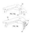
- FIG. 13a-13e schematically illustrates the cross sectional views of the receiving member 100 and the insertion member 200 in a first engagement of the assembly according to another embodiment of the present invention.
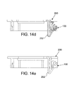
- the insertion member 200 is pre-assembled or factory-assembled to the receiving member 100 in the first engagement stage. At this stage movement of the insertion member 200 in all degrees of freedom are restricted accept angular adjustability. After aligning the angular position correctly, the bracket 202 of the insertion member may be pushed to the second engagement state, where the insertion member is restricted of movement in all six degrees of freedom (illustrated in FIG. 14a-14e ). In such preassembled case before doing final snapping, the parts remain in first engagement position where only option of rotation of the top part with respect to bottom housing is available.
- the number of brackets may vary as per the size of the box. In yet another embodiment, there may be guiding member at one end and bracket at another end.
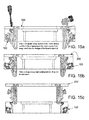
- FIG. 15a-15c schematically illustrates the removal mechanism of the insertion member 200 from the receiving member 100 according to one embodiment of the present invention.
- FIG. 15a shows the teeth unit 204 in fully engaged sate with the slots 106. In this position the brackets 202 may be pushed inward to release the teeth unit 204 from the slots 106. This may be done using the hand of the operator or with the help of a screw driver. By doing this, the teeth unit 204 disengage from the slots 106 and is ready to be released, as shown in the FIG. 15b . In this stage, the insertion member 200 may be pulled outward to disengage it completely from the receiving member 100. In this way the assembly is disengaged and may be adjusted for reengagement.
- the components of the assembly members are made of electrically non-conductive plastic material. Therefore, in case similar assembly is used for electrical box, there is no chance of short-circuit and damage of live wires from such assembly members. Further, this assembly avoids using screws and other metal parts. Use of snap-in assembly makes it quicker for installation and dismantling the assembly. No use of tools or screwdriver, renders such assembly as tool-less or tool-free assembly.
Landscapes
- Engineering & Computer Science (AREA)
- Architecture (AREA)
- Civil Engineering (AREA)
- Structural Engineering (AREA)
- Connection Of Plates (AREA)
Applications Claiming Priority (1)
| Application Number | Priority Date | Filing Date | Title |
|---|---|---|---|
| IN4302CH2011 | 2011-12-09 |
Publications (3)
| Publication Number | Publication Date |
|---|---|
| EP2602888A2 true EP2602888A2 (de) | 2013-06-12 |
| EP2602888A3 EP2602888A3 (de) | 2015-01-07 |
| EP2602888B1 EP2602888B1 (de) | 2015-11-25 |
Family
ID=47678470
Family Applications (1)
| Application Number | Title | Priority Date | Filing Date |
|---|---|---|---|
| EP12195530.6A Not-in-force EP2602888B1 (de) | 2011-12-09 | 2012-12-04 | Lösbare Sperrvorrichtung mit Winkeleinstellbarkeit |
Country Status (1)
| Country | Link |
|---|---|
| EP (1) | EP2602888B1 (de) |
Cited By (9)
| Publication number | Priority date | Publication date | Assignee | Title |
|---|---|---|---|---|
| WO2015049441A1 (fr) * | 2013-10-04 | 2015-04-09 | Legrand France | Support d'appareillage comportant des moyens d'encliquetage verrouillables |
| EP2852016A3 (de) * | 2013-09-23 | 2015-06-03 | Berker GmbH & Co. KG | Elektrisches/elektronisches Installationsgerät |
| FR3020514A1 (fr) * | 2014-04-28 | 2015-10-30 | Legrand France | Appareillage electrique a assemblage securise |
| FR3020518A1 (fr) * | 2014-04-28 | 2015-10-30 | Legrand France | Module d'appareillage electrique a encliqueter dans une boite electrique |
| FR3020516A1 (fr) * | 2014-04-28 | 2015-10-30 | Legrand France | Appareillage electrique a engager dans une boite electrique avec une orientation reglable |
| CH715901A1 (de) * | 2019-03-01 | 2020-09-15 | Morach Christoph | Set für Elektroinstallationen. |
| GB2589981A (en) * | 2019-10-29 | 2021-06-16 | Aecom | Electrical systems for structures |
| WO2021122043A1 (fr) * | 2019-12-20 | 2021-06-24 | Legrand France | Boite electrique en deux parties |
| RU2814945C1 (ru) * | 2019-12-20 | 2024-03-06 | Легран Франс | Электрическая коробка из двух частей |
Family Cites Families (5)
| Publication number | Priority date | Publication date | Assignee | Title |
|---|---|---|---|---|
| AT404080B (de) * | 1994-11-04 | 1998-08-25 | Putz Georg | Elektroinstallationsdose für die montage in wänden, insbesondere hohlwänden |
| CA2166362A1 (en) * | 1995-01-23 | 1996-07-24 | Karl Yetter | Device box with integral latching arrangement |
| US6376770B1 (en) * | 2000-02-28 | 2002-04-23 | Douglas Hyde | Quick connecting universal electrical box and wiring system |
| AU2003214029A1 (en) * | 2002-03-27 | 2003-10-08 | Daxtor Aps | Expansion unit |
| US6720512B1 (en) * | 2003-03-24 | 2004-04-13 | Dan Rothbauer | Surface mount switch plate |
-
2012
- 2012-12-04 EP EP12195530.6A patent/EP2602888B1/de not_active Not-in-force
Non-Patent Citations (1)
| Title |
|---|
| None |
Cited By (23)
| Publication number | Priority date | Publication date | Assignee | Title |
|---|---|---|---|---|
| EP2852016A3 (de) * | 2013-09-23 | 2015-06-03 | Berker GmbH & Co. KG | Elektrisches/elektronisches Installationsgerät |
| WO2015049441A1 (fr) * | 2013-10-04 | 2015-04-09 | Legrand France | Support d'appareillage comportant des moyens d'encliquetage verrouillables |
| FR3011693A1 (fr) * | 2013-10-04 | 2015-04-10 | Legrand France | Support d'appareillage comportant des moyens d'encliquetage verrouillables |
| WO2015166162A3 (fr) * | 2014-04-28 | 2016-04-28 | Legrand France | Appareillage électrique a assemblage sécurisé |
| CN106463927A (zh) * | 2014-04-28 | 2017-02-22 | 勒格朗法国公司 | 旨在卡接到电箱中的电气设备模块 |
| FR3020516A1 (fr) * | 2014-04-28 | 2015-10-30 | Legrand France | Appareillage electrique a engager dans une boite electrique avec une orientation reglable |
| WO2015166161A2 (fr) | 2014-04-28 | 2015-11-05 | Legrand France | Module d'appareillage électrique a encliqueter dans une boite électrique |
| WO2015166163A2 (fr) | 2014-04-28 | 2015-11-05 | Legrand France | Appareillage electrique a engager dans une boite electrique avec une orientation reglable |
| WO2015166161A3 (fr) * | 2014-04-28 | 2016-04-28 | Legrand France | Module d'appareillage électrique a encliqueter dans une boite électrique |
| WO2015166163A3 (fr) * | 2014-04-28 | 2016-04-28 | Legrand France | Appareillage electrique a engager dans une boite electrique avec une orientation reglable |
| FR3020514A1 (fr) * | 2014-04-28 | 2015-10-30 | Legrand France | Appareillage electrique a assemblage securise |
| CN106463926A (zh) * | 2014-04-28 | 2017-02-22 | 勒格朗法国公司 | 安全组装的电气设备 |
| FR3020518A1 (fr) * | 2014-04-28 | 2015-10-30 | Legrand France | Module d'appareillage electrique a encliqueter dans une boite electrique |
| US10128645B2 (en) | 2014-04-28 | 2018-11-13 | Legrand France | Secured assembly electrical apparatus |
| CN106463926B (zh) * | 2014-04-28 | 2019-02-22 | 勒格朗法国公司 | 安全组装的电气设备 |
| RU2681088C2 (ru) * | 2014-04-28 | 2019-03-04 | Легран Франс | Электрическое устройство с защищенным соединением |
| CN106463927B (zh) * | 2014-04-28 | 2019-07-23 | 勒格朗法国公司 | 旨在卡接到电箱中的电气设备模块 |
| CH715901A1 (de) * | 2019-03-01 | 2020-09-15 | Morach Christoph | Set für Elektroinstallationen. |
| GB2589981A (en) * | 2019-10-29 | 2021-06-16 | Aecom | Electrical systems for structures |
| WO2021122043A1 (fr) * | 2019-12-20 | 2021-06-24 | Legrand France | Boite electrique en deux parties |
| CN114830477A (zh) * | 2019-12-20 | 2022-07-29 | 勒格朗法国公司 | 两部件式电气壳体 |
| RU2814945C1 (ru) * | 2019-12-20 | 2024-03-06 | Легран Франс | Электрическая коробка из двух частей |
| CN114830477B (zh) * | 2019-12-20 | 2024-04-26 | 勒格朗法国公司 | 两部件式电气壳体 |
Also Published As
| Publication number | Publication date |
|---|---|
| EP2602888B1 (de) | 2015-11-25 |
| EP2602888A3 (de) | 2015-01-07 |
Similar Documents
| Publication | Publication Date | Title |
|---|---|---|
| EP2602888B1 (de) | Lösbare Sperrvorrichtung mit Winkeleinstellbarkeit | |
| US7351116B2 (en) | Connecting element | |
| EP1655815B1 (de) | Gehäuseanordnung mit mindestens einer Verbindungsdose | |
| US9686877B2 (en) | Locking structure between member to be supported and supporting body | |
| US10340676B2 (en) | Electrical device protective housing | |
| US10501928B2 (en) | Split connector and modular frame comprising such a split connector | |
| EP2364878A1 (de) | Montagestruktur für die lampe eines fahrzeuginsassenraums | |
| EP2751606B1 (de) | Apparat und verfahren zur werkzeuglosen, lösbaren befestigung von komponenten an einem glasfaserverteilerschrank | |
| US20070045308A1 (en) | Pull out extension contained in electrical box | |
| KR200484505Y1 (ko) | 알루미늄 랙 캐비넷 조립체 | |
| CN111684675A (zh) | 用于安装电气部件的适配器 | |
| JP2013115164A (ja) | ケーブル整線部材 | |
| SG185603A1 (en) | Mounting arrangement for a door actuator | |
| EP2874175A1 (de) | Befestigungsstruktur für sicherungshalter und abdeckung | |
| JP2003333730A (ja) | 軽量間仕切り壁用配線ボックス及び軽量間仕切り壁用配線ボックス装置 | |
| US12330786B2 (en) | Fastening system, monument and method for attaching a fixture to a monument | |
| EP2663170A2 (de) | Befestigungsmittel, Befestigungsanordnung und Verfahren zur Herstellung einer Befestigungsanordnung | |
| US7939981B2 (en) | Electrical motor and method for connection of an electrical motor to a connector flange | |
| EP2657172B1 (de) | Kabelbehandlungsvorrichtung für einen aufzug | |
| EP3059822A1 (de) | Elektroinstallationskastenanordnung | |
| DE202015006719U1 (de) | Kabel-, Geräteeinbau- und lnstallationskanalsystem | |
| US20110192628A1 (en) | Breaker tray for a panelboard cover | |
| JP5879619B2 (ja) | ケーブル整線部材の取付構造 | |
| EP2423512B1 (de) | Lüftereinheit | |
| CN205723203U (zh) | 可预安装调节结构及电控装置 |
Legal Events
| Date | Code | Title | Description |
|---|---|---|---|
| PUAI | Public reference made under article 153(3) epc to a published international application that has entered the european phase |
Free format text: ORIGINAL CODE: 0009012 |
|
| AK | Designated contracting states |
Kind code of ref document: A2 Designated state(s): AL AT BE BG CH CY CZ DE DK EE ES FI FR GB GR HR HU IE IS IT LI LT LU LV MC MK MT NL NO PL PT RO RS SE SI SK SM TR |
|
| AX | Request for extension of the european patent |
Extension state: BA ME |
|
| PUAL | Search report despatched |
Free format text: ORIGINAL CODE: 0009013 |
|
| AK | Designated contracting states |
Kind code of ref document: A3 Designated state(s): AL AT BE BG CH CY CZ DE DK EE ES FI FR GB GR HR HU IE IS IT LI LT LU LV MC MK MT NL NO PL PT RO RS SE SI SK SM TR |
|
| AX | Request for extension of the european patent |
Extension state: BA ME |
|
| RIC1 | Information provided on ipc code assigned before grant |
Ipc: H02G 3/12 20060101AFI20141201BHEP |
|
| 17P | Request for examination filed |
Effective date: 20150304 |
|
| RBV | Designated contracting states (corrected) |
Designated state(s): AL AT BE BG CH CY CZ DE DK EE ES FI FR GB GR HR HU IE IS IT LI LT LU LV MC MK MT NL NO PL PT RO RS SE SI SK SM TR |
|
| GRAP | Despatch of communication of intention to grant a patent |
Free format text: ORIGINAL CODE: EPIDOSNIGR1 |
|
| INTG | Intention to grant announced |
Effective date: 20150611 |
|
| GRAS | Grant fee paid |
Free format text: ORIGINAL CODE: EPIDOSNIGR3 |
|
| GRAA | (expected) grant |
Free format text: ORIGINAL CODE: 0009210 |
|
| AK | Designated contracting states |
Kind code of ref document: B1 Designated state(s): AL AT BE BG CH CY CZ DE DK EE ES FI FR GB GR HR HU IE IS IT LI LT LU LV MC MK MT NL NO PL PT RO RS SE SI SK SM TR |
|
| REG | Reference to a national code |
Ref country code: GB Ref legal event code: FG4D |
|
| REG | Reference to a national code |
Ref country code: CH Ref legal event code: EP |
|
| REG | Reference to a national code |
Ref country code: AT Ref legal event code: REF Ref document number: 763030 Country of ref document: AT Kind code of ref document: T Effective date: 20151215 |
|
| REG | Reference to a national code |
Ref country code: IE Ref legal event code: FG4D |
|
| REG | Reference to a national code |
Ref country code: DE Ref legal event code: R096 Ref document number: 602012012591 Country of ref document: DE |
|
| REG | Reference to a national code |
Ref country code: FR Ref legal event code: PLFP Year of fee payment: 4 |
|
| REG | Reference to a national code |
Ref country code: SE Ref legal event code: TRGR |
|
| REG | Reference to a national code |
Ref country code: LT Ref legal event code: MG4D |
|
| REG | Reference to a national code |
Ref country code: NL Ref legal event code: MP Effective date: 20160225 |
|
| REG | Reference to a national code |
Ref country code: AT Ref legal event code: MK05 Ref document number: 763030 Country of ref document: AT Kind code of ref document: T Effective date: 20151125 |
|
| PG25 | Lapsed in a contracting state [announced via postgrant information from national office to epo] |
Ref country code: HR Free format text: LAPSE BECAUSE OF FAILURE TO SUBMIT A TRANSLATION OF THE DESCRIPTION OR TO PAY THE FEE WITHIN THE PRESCRIBED TIME-LIMIT Effective date: 20151125 Ref country code: LT Free format text: LAPSE BECAUSE OF FAILURE TO SUBMIT A TRANSLATION OF THE DESCRIPTION OR TO PAY THE FEE WITHIN THE PRESCRIBED TIME-LIMIT Effective date: 20151125 Ref country code: IS Free format text: LAPSE BECAUSE OF FAILURE TO SUBMIT A TRANSLATION OF THE DESCRIPTION OR TO PAY THE FEE WITHIN THE PRESCRIBED TIME-LIMIT Effective date: 20160325 Ref country code: NO Free format text: LAPSE BECAUSE OF FAILURE TO SUBMIT A TRANSLATION OF THE DESCRIPTION OR TO PAY THE FEE WITHIN THE PRESCRIBED TIME-LIMIT Effective date: 20160225 Ref country code: ES Free format text: LAPSE BECAUSE OF FAILURE TO SUBMIT A TRANSLATION OF THE DESCRIPTION OR TO PAY THE FEE WITHIN THE PRESCRIBED TIME-LIMIT Effective date: 20151125 Ref country code: NL Free format text: LAPSE BECAUSE OF FAILURE TO SUBMIT A TRANSLATION OF THE DESCRIPTION OR TO PAY THE FEE WITHIN THE PRESCRIBED TIME-LIMIT Effective date: 20151125 |
|
| PG25 | Lapsed in a contracting state [announced via postgrant information from national office to epo] |
Ref country code: LV Free format text: LAPSE BECAUSE OF FAILURE TO SUBMIT A TRANSLATION OF THE DESCRIPTION OR TO PAY THE FEE WITHIN THE PRESCRIBED TIME-LIMIT Effective date: 20151125 Ref country code: FI Free format text: LAPSE BECAUSE OF FAILURE TO SUBMIT A TRANSLATION OF THE DESCRIPTION OR TO PAY THE FEE WITHIN THE PRESCRIBED TIME-LIMIT Effective date: 20151125 Ref country code: RS Free format text: LAPSE BECAUSE OF FAILURE TO SUBMIT A TRANSLATION OF THE DESCRIPTION OR TO PAY THE FEE WITHIN THE PRESCRIBED TIME-LIMIT Effective date: 20151125 Ref country code: BE Free format text: LAPSE BECAUSE OF NON-PAYMENT OF DUE FEES Effective date: 20151231 Ref country code: GR Free format text: LAPSE BECAUSE OF FAILURE TO SUBMIT A TRANSLATION OF THE DESCRIPTION OR TO PAY THE FEE WITHIN THE PRESCRIBED TIME-LIMIT Effective date: 20160226 Ref country code: AT Free format text: LAPSE BECAUSE OF FAILURE TO SUBMIT A TRANSLATION OF THE DESCRIPTION OR TO PAY THE FEE WITHIN THE PRESCRIBED TIME-LIMIT Effective date: 20151125 Ref country code: PL Free format text: LAPSE BECAUSE OF FAILURE TO SUBMIT A TRANSLATION OF THE DESCRIPTION OR TO PAY THE FEE WITHIN THE PRESCRIBED TIME-LIMIT Effective date: 20151125 Ref country code: PT Free format text: LAPSE BECAUSE OF FAILURE TO SUBMIT A TRANSLATION OF THE DESCRIPTION OR TO PAY THE FEE WITHIN THE PRESCRIBED TIME-LIMIT Effective date: 20160325 |
|
| PG25 | Lapsed in a contracting state [announced via postgrant information from national office to epo] |
Ref country code: CZ Free format text: LAPSE BECAUSE OF FAILURE TO SUBMIT A TRANSLATION OF THE DESCRIPTION OR TO PAY THE FEE WITHIN THE PRESCRIBED TIME-LIMIT Effective date: 20151125 Ref country code: IT Free format text: LAPSE BECAUSE OF FAILURE TO SUBMIT A TRANSLATION OF THE DESCRIPTION OR TO PAY THE FEE WITHIN THE PRESCRIBED TIME-LIMIT Effective date: 20151125 |
|
| REG | Reference to a national code |
Ref country code: CH Ref legal event code: PL |
|
| REG | Reference to a national code |
Ref country code: DE Ref legal event code: R097 Ref document number: 602012012591 Country of ref document: DE |
|
| PG25 | Lapsed in a contracting state [announced via postgrant information from national office to epo] |
Ref country code: EE Free format text: LAPSE BECAUSE OF FAILURE TO SUBMIT A TRANSLATION OF THE DESCRIPTION OR TO PAY THE FEE WITHIN THE PRESCRIBED TIME-LIMIT Effective date: 20151125 Ref country code: RO Free format text: LAPSE BECAUSE OF FAILURE TO SUBMIT A TRANSLATION OF THE DESCRIPTION OR TO PAY THE FEE WITHIN THE PRESCRIBED TIME-LIMIT Effective date: 20151125 Ref country code: SM Free format text: LAPSE BECAUSE OF FAILURE TO SUBMIT A TRANSLATION OF THE DESCRIPTION OR TO PAY THE FEE WITHIN THE PRESCRIBED TIME-LIMIT Effective date: 20151125 Ref country code: DK Free format text: LAPSE BECAUSE OF FAILURE TO SUBMIT A TRANSLATION OF THE DESCRIPTION OR TO PAY THE FEE WITHIN THE PRESCRIBED TIME-LIMIT Effective date: 20151125 Ref country code: SK Free format text: LAPSE BECAUSE OF FAILURE TO SUBMIT A TRANSLATION OF THE DESCRIPTION OR TO PAY THE FEE WITHIN THE PRESCRIBED TIME-LIMIT Effective date: 20151125 |
|
| REG | Reference to a national code |
Ref country code: IE Ref legal event code: MM4A |
|
| PG25 | Lapsed in a contracting state [announced via postgrant information from national office to epo] |
Ref country code: MC Free format text: LAPSE BECAUSE OF FAILURE TO SUBMIT A TRANSLATION OF THE DESCRIPTION OR TO PAY THE FEE WITHIN THE PRESCRIBED TIME-LIMIT Effective date: 20151125 |
|
| PLBE | No opposition filed within time limit |
Free format text: ORIGINAL CODE: 0009261 |
|
| STAA | Information on the status of an ep patent application or granted ep patent |
Free format text: STATUS: NO OPPOSITION FILED WITHIN TIME LIMIT |
|
| PG25 | Lapsed in a contracting state [announced via postgrant information from national office to epo] |
Ref country code: IE Free format text: LAPSE BECAUSE OF NON-PAYMENT OF DUE FEES Effective date: 20151204 Ref country code: CH Free format text: LAPSE BECAUSE OF NON-PAYMENT OF DUE FEES Effective date: 20151231 Ref country code: LI Free format text: LAPSE BECAUSE OF NON-PAYMENT OF DUE FEES Effective date: 20151231 |
|
| 26N | No opposition filed |
Effective date: 20160826 |
|
| PG25 | Lapsed in a contracting state [announced via postgrant information from national office to epo] |
Ref country code: SI Free format text: LAPSE BECAUSE OF FAILURE TO SUBMIT A TRANSLATION OF THE DESCRIPTION OR TO PAY THE FEE WITHIN THE PRESCRIBED TIME-LIMIT Effective date: 20151125 |
|
| REG | Reference to a national code |
Ref country code: FR Ref legal event code: PLFP Year of fee payment: 5 |
|
| PG25 | Lapsed in a contracting state [announced via postgrant information from national office to epo] |
Ref country code: BE Free format text: LAPSE BECAUSE OF FAILURE TO SUBMIT A TRANSLATION OF THE DESCRIPTION OR TO PAY THE FEE WITHIN THE PRESCRIBED TIME-LIMIT Effective date: 20151125 |
|
| PG25 | Lapsed in a contracting state [announced via postgrant information from national office to epo] |
Ref country code: BG Free format text: LAPSE BECAUSE OF FAILURE TO SUBMIT A TRANSLATION OF THE DESCRIPTION OR TO PAY THE FEE WITHIN THE PRESCRIBED TIME-LIMIT Effective date: 20151125 Ref country code: HU Free format text: LAPSE BECAUSE OF FAILURE TO SUBMIT A TRANSLATION OF THE DESCRIPTION OR TO PAY THE FEE WITHIN THE PRESCRIBED TIME-LIMIT; INVALID AB INITIO Effective date: 20121204 |
|
| PG25 | Lapsed in a contracting state [announced via postgrant information from national office to epo] |
Ref country code: CY Free format text: LAPSE BECAUSE OF FAILURE TO SUBMIT A TRANSLATION OF THE DESCRIPTION OR TO PAY THE FEE WITHIN THE PRESCRIBED TIME-LIMIT Effective date: 20151125 |
|
| GBPC | Gb: european patent ceased through non-payment of renewal fee |
Effective date: 20161204 |
|
| PG25 | Lapsed in a contracting state [announced via postgrant information from national office to epo] |
Ref country code: MT Free format text: LAPSE BECAUSE OF FAILURE TO SUBMIT A TRANSLATION OF THE DESCRIPTION OR TO PAY THE FEE WITHIN THE PRESCRIBED TIME-LIMIT Effective date: 20151125 |
|
| REG | Reference to a national code |
Ref country code: FR Ref legal event code: PLFP Year of fee payment: 6 |
|
| PG25 | Lapsed in a contracting state [announced via postgrant information from national office to epo] |
Ref country code: LU Free format text: LAPSE BECAUSE OF NON-PAYMENT OF DUE FEES Effective date: 20151204 Ref country code: GB Free format text: LAPSE BECAUSE OF NON-PAYMENT OF DUE FEES Effective date: 20161204 |
|
| PG25 | Lapsed in a contracting state [announced via postgrant information from national office to epo] |
Ref country code: TR Free format text: LAPSE BECAUSE OF FAILURE TO SUBMIT A TRANSLATION OF THE DESCRIPTION OR TO PAY THE FEE WITHIN THE PRESCRIBED TIME-LIMIT Effective date: 20151125 Ref country code: MK Free format text: LAPSE BECAUSE OF FAILURE TO SUBMIT A TRANSLATION OF THE DESCRIPTION OR TO PAY THE FEE WITHIN THE PRESCRIBED TIME-LIMIT Effective date: 20151125 |
|
| PG25 | Lapsed in a contracting state [announced via postgrant information from national office to epo] |
Ref country code: AL Free format text: LAPSE BECAUSE OF FAILURE TO SUBMIT A TRANSLATION OF THE DESCRIPTION OR TO PAY THE FEE WITHIN THE PRESCRIBED TIME-LIMIT Effective date: 20151125 |
|
| PGFP | Annual fee paid to national office [announced via postgrant information from national office to epo] |
Ref country code: SE Payment date: 20211210 Year of fee payment: 10 Ref country code: DE Payment date: 20211207 Year of fee payment: 10 Ref country code: FR Payment date: 20211216 Year of fee payment: 10 |
|
| REG | Reference to a national code |
Ref country code: DE Ref legal event code: R119 Ref document number: 602012012591 Country of ref document: DE |
|
| REG | Reference to a national code |
Ref country code: SE Ref legal event code: EUG |
|
| PG25 | Lapsed in a contracting state [announced via postgrant information from national office to epo] |
Ref country code: SE Free format text: LAPSE BECAUSE OF NON-PAYMENT OF DUE FEES Effective date: 20221205 Ref country code: DE Free format text: LAPSE BECAUSE OF NON-PAYMENT OF DUE FEES Effective date: 20230701 |
|
| PG25 | Lapsed in a contracting state [announced via postgrant information from national office to epo] |
Ref country code: FR Free format text: LAPSE BECAUSE OF NON-PAYMENT OF DUE FEES Effective date: 20221231 |