EP2602891A2 - Hermetische Abdeckung für einen elektrischen Steckverbinder - Google Patents
Hermetische Abdeckung für einen elektrischen Steckverbinder Download PDFInfo
- Publication number
- EP2602891A2 EP2602891A2 EP12150767.7A EP12150767A EP2602891A2 EP 2602891 A2 EP2602891 A2 EP 2602891A2 EP 12150767 A EP12150767 A EP 12150767A EP 2602891 A2 EP2602891 A2 EP 2602891A2
- Authority
- EP
- European Patent Office
- Prior art keywords
- fittings
- elastic
- fitting
- hermetic cover
- hermetic
- Prior art date
- Legal status (The legal status is an assumption and is not a legal conclusion. Google has not performed a legal analysis and makes no representation as to the accuracy of the status listed.)
- Withdrawn
Links
- 230000003019 stabilising effect Effects 0.000 claims abstract description 8
- 239000002184 metal Substances 0.000 claims description 5
- 229920001296 polysiloxane Polymers 0.000 claims description 5
- 230000001012 protector Effects 0.000 claims description 4
- 239000000463 material Substances 0.000 claims description 2
- 230000005855 radiation Effects 0.000 description 7
- 239000000428 dust Substances 0.000 description 4
- 238000010276 construction Methods 0.000 description 3
- 238000001816 cooling Methods 0.000 description 3
- 238000009413 insulation Methods 0.000 description 3
- 239000011810 insulating material Substances 0.000 description 2
- 238000004519 manufacturing process Methods 0.000 description 2
- 239000002826 coolant Substances 0.000 description 1
- 230000003247 decreasing effect Effects 0.000 description 1
- 238000010616 electrical installation Methods 0.000 description 1
- 239000012528 membrane Substances 0.000 description 1
- 238000007789 sealing Methods 0.000 description 1
- 239000007787 solid Substances 0.000 description 1
- 239000000126 substance Substances 0.000 description 1
- XLYOFNOQVPJJNP-UHFFFAOYSA-N water Substances O XLYOFNOQVPJJNP-UHFFFAOYSA-N 0.000 description 1
Images



Classifications
-
- H—ELECTRICITY
- H02—GENERATION; CONVERSION OR DISTRIBUTION OF ELECTRIC POWER
- H02G—INSTALLATION OF ELECTRIC CABLES OR LINES, OR OF COMBINED OPTICAL AND ELECTRIC CABLES OR LINES
- H02G15/00—Cable fittings
- H02G15/08—Cable junctions
- H02G15/10—Cable junctions protected by boxes, e.g. by distribution, connection or junction boxes
- H02G15/115—Boxes split perpendicularly to main cable direction
Definitions
- the current invention is a hermetic cover for an electrical connector, especially a connector for electrical supply cables with external sheath and wire insulation.
- Hermetic protection for an electrical connector against moisture and dust is especially useful in electrical devices with infrared or light emitters, where such protection is required to ensure electrical safety.
- the connections are insulated by leading the cables out of the device and into a separate hermetic box or by hermetically insulating the whole casing of the device or a part of it, in each case making the insulation fit a particular casing.
- Such solutions are not universal, take up space, while the insulation of the whole casing significantly increases the manufacturing cost of the device.
- hermetic casings cause an additional problem connected with their cooling.
- one of the known solutions involves a metal base for the electrical elements of a water-tight lighting fitting installed on a plastic base, with a reflector, fluorescent lamps and the top cover attached to the whole construction.
- This solution lacks universality, since for infraread heat emitters full casing creates problems with releasing heat from the electrical connectors, the emitter and the casing.
- patent description no. WO2005036928 includes a radiation device, in which the thermal radiation emitter is protected against vibration and mechanical tension caused by thermal expansion occurring in such devices.
- This device includes a load-bearing casing equipped with two hooks that carry a pipe radiation emitter.
- the pipe radiation emitter is connected with hook units using elastic connecting elements, each of which is installed on the end of the emitter so that it serves shock-absorbing and insulating purposes.
- the hook units determine the cover area, where the electrical connector protectors are installed.
- Patent no. PL-208939 describes a minimised cover in the form of a separate element designating a hermetic space, consisting of seals and a cableway which is circumferentially adjacent, on its internal or external surface, to the seal situated on the end of the pipe infrared radiation emitter, while the other side it is circumferentially adjacent, on its internal or external surface, to the other seal which is adj acent to power supply cables or preferably adj acent to the end of the additional elastic cover of the power supply cables, Such a cover protects the direct connection to the emitter, but is not a universal cover for electrical connectors.
- Patent description no. US 5266742 shows a connector cover consisting of elastic conical internal bushes installed in an external tube-shaped head with conical tips on both ends.
- the conical tips of the external head are connected with the internal cylindrical element with a bolt joint.
- the inside of the goblet-shaped space is filled with an insulating material.
- a hermetic cover of an electrical connector consisting of elastic, circumferentially connected fittings forming a closed chamber, with each of these elastic fittings having at least one cableway, according to the current invention, is characterized in that the neighbouring elastic fittings fit inside each other and their side surfaces are tightly adjacent to each other their whole lengths or along the lengths limited by retainer protrusions, while it is preferred if the elastic fitting inserted into another elastic fitting has at least one built-in circumferential stiffening element in the form of a narrow clamp located in the area of contact between the two fittings.
- the hermetic cover is characterized in that it the clamp combined with the fitting is preferably convex on the outer surface of the fitting.
- each of these elastic fittings has a preferred tubular shape, while the end fittings are closed with a cap on one end.
- the hermetic cover for an electrical connection is also characterised in that at least one cableway is formed in each end cap, with a diameter slightly smaller than the diameter of the cable or the diameter of the bundle introduced into the cover.
- the hermetic cover for an electrical connection is also characterised in that at least one of the elastic fittings preferably has additional openings, protrusions and bend protectors on its side surface with a diameter slightly smaller than the diameter of the cables or the bundle introduced into the cover.
- the hermetic cover for an electrical connection is also characterised in that the stabilising protrusions situated inside each external fitting are located at a depth preventing the fittings from sliding out by themselves or from the connection becoming non-hermetic, preferably not less than 1/3 of the length of the fitting.
- the hermetic cover for an electrical connector is also characterised in that the clamp is made of stiff material, preferably metal or plastic.
- the hermetic cover for an electrical connector is also characterised in that the elastic fittings are made of high-temperature silicone.
- the hermetic cover for an electrical connector manufactured according to the present invention is simple in its construction, universal in application and characterised by a highly effective protection of electrical contacts against moisture and dust. Therefore, it meets the safety requirements for devices operating outdoors or in high moisture and high dust concentration environments.
- the use of the clamp makes it easier to slide the fittings together, as well as causes the fittings to be in tight contact with each other, forming a hermetic space.
- the internal stabilising protrusions provide deep enough overlapping of the fittings at the required depth, which prevents the connector from becoming non-hermetic. This solution allows for abandoning the existing construction of heat and light emitters, and especially infrared radiation emitters, whose complex casing shapes were selected according to complicated hermetic covers.
- Fig. 1 shows a hermetic cover of a connector consisting of two fittings in a version without a stiffening clamp, presented in the cross-section
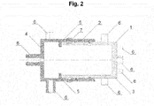
- Fig. 2 shows a hermetic cover consisting of two fittings with a stiffening clamp with an additional side cable channel, shown in the cross-section
- Fig. 3 shows a hermetic cover consisting of three fittings with a stiffening clamp and an additional side cable channel, shown in the cross-section
- Fig. 4 to Fig. 7 show different variants of combining the fittings in a cover with different branch-off points for cables
- Fig. 8 to Fig. 10 show example shapes of the cross-sections of the fittings.
- the embodiment shown in fig. 1 includes a hermetic cover for an electrical connector consisting of an internal elastic fitting 1 and an external elastic fitting pulled over it 2 , that form a hermetic space together.
- the internal elastic fitting 1 is tube-shaped and closed with a cap on one end 3 .
- the external fitting 2 is also tube-shaped with a slightly larger diameter, closed with a cap on one end 4 .
- the inside of the external fitting 2 includes stabilising protrusions 5 that regulate the depth of the overlap of fitting 2 and fitting 1 .
- Elastic fittings 1 and 2 are made of high-temperature silicone, and each one is equipped with a cableway 6 in the cap at the end. The diameter of cableways 6 are always slightly smaller than the diameter of the cables or bundles, which makes them fit tightly around the cables. Cableways 6 are protected by means of a thin membranes that can be easily broken.
- the same connector can be equipped with differently shaped elastic fittings 1 and 2 , but these shapes always have to be identical in the area of their contact.
- hermetic cover for an electrical connectpr consists of an internal elastic fitting 1 and an external elastic fitting pulled over it 2, that form a hermetic space together.
- the internal elastic fitting 1 is tube-shaped and closed on one end with a cap 3, and includes a built-in circumferential stiffening narrow clamp 7.
- Clamp 7 is made of metal and installed in fitting 1 so that it slightly protrudes on the outer wall.
- Cap 3 and the side surface of fitting 1 include cableways 6.
- External fitting 2 is also tube-shaped with a slightly larger diameter, closed with a cap on one end 4 .
- the inside of external fitting 2 include stabilising protrusions 5 that regulate the depth of the overlap of fitting 2 and fitting 1 .
- Cap 4 and the side surface of fitting 1 include cableways 6.
- Elastic fittings 1 and 2 are made of high-temperature silicone.
- the diameter of the openings 6 is slightly smaller than the diameter of the cables or bundles, which makes them fit tightly around the cables.
- the same connection can be equipped with differently shaped elastic fittings 1 and 2 , but these shapes have to be identical in the area of their contact.
- FIG. 3 Another embodiment shown in Fig. 3 includes a hermetic cover for an electrical connector consisting of internal elastic fitting 1 and two external elastic fittings pulled over it 2 , that form a hermetic space together.
- Internal elastic fitting 1 is tube-shaped and it includes built-in circumferential stiffening narrow clamps 7.
- Clamps 7 are made of metal and are installed in fitting 1 on both sides of the bush so that they slightly protrude on the outer wall.
- External fittings 2 are also tube-shaped with a slightly larger diameter, each one closed with a cap on one end 4 .
- the inside of external fittings 2 include stabilising protrusions 5 that regulate the depth of the overlap of fitting 2 and fitting 1 .
- Elastic fittings 1 and 2 are made of high-temperature silicone, and each of them includes numerous cableways 6 in the form of protrusions and bend protectors, the type and quantity of which depends on the need.
- the diameter of the openings is always slightly smaller than the diameter of the cables or bundles, which makes them fit tightly around the cables.
- the same connector can be equipped with differently shaped elastic fittings 1 and 2 , shown in Fig. 8 to Fig. 10 , but these shapes have to be identical in the area of their contact.
- Other variants of connections between fittings 1 and 2 are shown in Fig. 4 to Fig. 7 .
- the embodiments of the invention were tested for tightness and IP protection.
- the IP protection tests were conducted under the following conditions:
Landscapes
- Connector Housings Or Holding Contact Members (AREA)
Applications Claiming Priority (1)
| Application Number | Priority Date | Filing Date | Title |
|---|---|---|---|
| PL397266A PL219674B1 (pl) | 2011-12-07 | 2011-12-07 | Hermetyczna osłona złącza elektrycznego |
Publications (2)
| Publication Number | Publication Date |
|---|---|
| EP2602891A2 true EP2602891A2 (de) | 2013-06-12 |
| EP2602891A3 EP2602891A3 (de) | 2014-08-20 |
Family
ID=45443049
Family Applications (1)
| Application Number | Title | Priority Date | Filing Date |
|---|---|---|---|
| EP12150767.7A Withdrawn EP2602891A3 (de) | 2011-12-07 | 2012-01-11 | Hermetische Abdeckung für einen elektrischen Steckverbinder |
Country Status (2)
| Country | Link |
|---|---|
| EP (1) | EP2602891A3 (de) |
| PL (1) | PL219674B1 (de) |
Cited By (2)
| Publication number | Priority date | Publication date | Assignee | Title |
|---|---|---|---|---|
| GB2518903A (en) * | 2013-10-07 | 2015-04-08 | Heat Outdoors Ltd | Improvements in and related to a waterproof connector |
| EP3174160A1 (de) * | 2015-11-30 | 2017-05-31 | GE Energy Power Conversion Technology Ltd | Abdeckung und verfahren zur abdeckung eines abschnitts wenigstens eines elektrischen leiters |
Citations (3)
| Publication number | Priority date | Publication date | Assignee | Title |
|---|---|---|---|---|
| PL208939A1 (pl) | 1978-08-08 | 1979-07-02 | Inst Budownictwa Mech | Elektromagnetyczny silownik wahliwy |
| US5266742A (en) | 1991-05-23 | 1993-11-30 | Siemens Aktiengesellschaft | Longitudinal water-tight cable sleeve |
| WO2005036928A1 (en) | 2003-10-10 | 2005-04-21 | Mo-El S.R.L. | A radiant device |
Family Cites Families (3)
| Publication number | Priority date | Publication date | Assignee | Title |
|---|---|---|---|---|
| NL50529C (de) * | 1938-09-07 | 1941-06-16 | ||
| PL208939B1 (pl) * | 2005-12-27 | 2011-06-30 | Andrzej Wroński | Wodoszczelne i/lub pyłoszczelne zabezpieczenie elektrycznego złącza rurkowego emitera promieniowania podczerwonego oraz promiennik grzewczy z rurkowym emiterem promieniowania podczerwonego |
| GB2478894B (en) * | 2009-01-21 | 2014-03-05 | Farrel Roy Brenner | Improvements in and relating to electrical connector housings |
-
2011
- 2011-12-07 PL PL397266A patent/PL219674B1/pl unknown
-
2012
- 2012-01-11 EP EP12150767.7A patent/EP2602891A3/de not_active Withdrawn
Patent Citations (3)
| Publication number | Priority date | Publication date | Assignee | Title |
|---|---|---|---|---|
| PL208939A1 (pl) | 1978-08-08 | 1979-07-02 | Inst Budownictwa Mech | Elektromagnetyczny silownik wahliwy |
| US5266742A (en) | 1991-05-23 | 1993-11-30 | Siemens Aktiengesellschaft | Longitudinal water-tight cable sleeve |
| WO2005036928A1 (en) | 2003-10-10 | 2005-04-21 | Mo-El S.R.L. | A radiant device |
Cited By (5)
| Publication number | Priority date | Publication date | Assignee | Title |
|---|---|---|---|---|
| GB2518903A (en) * | 2013-10-07 | 2015-04-08 | Heat Outdoors Ltd | Improvements in and related to a waterproof connector |
| EP3174160A1 (de) * | 2015-11-30 | 2017-05-31 | GE Energy Power Conversion Technology Ltd | Abdeckung und verfahren zur abdeckung eines abschnitts wenigstens eines elektrischen leiters |
| WO2017093159A1 (en) * | 2015-11-30 | 2017-06-08 | Ge Energy Power Conversion Technology Limited | Cover and process to cover a section of at least one electrical conductor |
| CN108496279A (zh) * | 2015-11-30 | 2018-09-04 | 通用电气能源能量变换技术有限公司 | 覆盖件和覆盖至少一个导电体的区段的过程 |
| US10483746B2 (en) * | 2015-11-30 | 2019-11-19 | Ge Energy Power Conversion Technology Ltd | Cover and process to cover a section of at least one electrical conductor |
Also Published As
| Publication number | Publication date |
|---|---|
| PL219674B1 (pl) | 2015-06-30 |
| PL397266A1 (pl) | 2013-06-10 |
| EP2602891A3 (de) | 2014-08-20 |
Similar Documents
| Publication | Publication Date | Title |
|---|---|---|
| KR101605562B1 (ko) | 안전 탱크용 전기 관통 접속 장치 | |
| JP4163957B2 (ja) | ケーブルグランドアセンブリ | |
| US7764871B2 (en) | Infrared heat irradiating device | |
| US9583903B1 (en) | Adapter for LED strip light | |
| RU2669789C2 (ru) | Соединительная система и соответствующий способ | |
| KR100432467B1 (ko) | 밀봉장치 | |
| RU180082U1 (ru) | Птицезащитное устройство для линий электропередач с подвесными полимерными изоляторами | |
| US8609990B2 (en) | Gasket for electric cables | |
| KR102118097B1 (ko) | 도관 어댑터를 구비하는 압축기를 위한 플러그 어셈블리 | |
| US20150315877A1 (en) | Pressure-blocking feedthru with pressure-balanced cable terminations | |
| US10330289B2 (en) | Cover for the support arrangement of a strip light system and strip light system | |
| US20130025912A1 (en) | High-voltage insulator | |
| WO2017168269A1 (en) | Power connectors for linear lighting | |
| US10985538B2 (en) | System and method for reducing air volume in a splitter | |
| ES3039346T3 (en) | Down conductor connection system, wind turbine lightning protection system, and method for arranging a down conductor connection system | |
| ES2610379T3 (es) | Carcasa empotrada para lámparas eléctricas | |
| PL219674B1 (pl) | Hermetyczna osłona złącza elektrycznego | |
| JP5662780B2 (ja) | 防爆固定装置 | |
| CN102570095A (zh) | 一种接线插头 | |
| US20080261429A1 (en) | Waterproof and/or dustproof protection device for electrical connector in tubular radiation emitter and methods of using the same | |
| EP2034798A2 (de) | Strahlungsvorrichtung | |
| US7399923B2 (en) | Electrical hermetic penetrant structure of low voltage | |
| KR101169716B1 (ko) | 접촉식 전원공급장치 | |
| RU46382U1 (ru) | Электрическая герметичная проходка низкого напряжения | |
| JP2019502946A (ja) | 絶縁体およびその製造方法 |
Legal Events
| Date | Code | Title | Description |
|---|---|---|---|
| PUAI | Public reference made under article 153(3) epc to a published international application that has entered the european phase |
Free format text: ORIGINAL CODE: 0009012 |
|
| AK | Designated contracting states |
Kind code of ref document: A2 Designated state(s): AL AT BE BG CH CY CZ DE DK EE ES FI FR GB GR HR HU IE IS IT LI LT LU LV MC MK MT NL NO PL PT RO RS SE SI SK SM TR |
|
| AX | Request for extension of the european patent |
Extension state: BA ME |
|
| PUAL | Search report despatched |
Free format text: ORIGINAL CODE: 0009013 |
|
| AK | Designated contracting states |
Kind code of ref document: A3 Designated state(s): AL AT BE BG CH CY CZ DE DK EE ES FI FR GB GR HR HU IE IS IT LI LT LU LV MC MK MT NL NO PL PT RO RS SE SI SK SM TR |
|
| AX | Request for extension of the european patent |
Extension state: BA ME |
|
| RIC1 | Information provided on ipc code assigned before grant |
Ipc: H02G 15/115 20060101AFI20140715BHEP |
|
| STAA | Information on the status of an ep patent application or granted ep patent |
Free format text: STATUS: THE APPLICATION IS DEEMED TO BE WITHDRAWN |
|
| 18D | Application deemed to be withdrawn |
Effective date: 20150221 |