EP2602973A1 - Sockelmodul und tragbares Endgerät damit - Google Patents
Sockelmodul und tragbares Endgerät damit Download PDFInfo
- Publication number
- EP2602973A1 EP2602973A1 EP12008045.2A EP12008045A EP2602973A1 EP 2602973 A1 EP2602973 A1 EP 2602973A1 EP 12008045 A EP12008045 A EP 12008045A EP 2602973 A1 EP2602973 A1 EP 2602973A1
- Authority
- EP
- European Patent Office
- Prior art keywords
- substrate
- mobile terminal
- socket module
- module
- coupling unit
- Prior art date
- Legal status (The legal status is an assumption and is not a legal conclusion. Google has not performed a legal analysis and makes no representation as to the accuracy of the status listed.)
- Granted
Links
- 239000000758 substrate Substances 0.000 claims abstract description 131
- 230000008878 coupling Effects 0.000 claims abstract description 46
- 238000010168 coupling process Methods 0.000 claims abstract description 46
- 238000005859 coupling reaction Methods 0.000 claims abstract description 46
- 238000012546 transfer Methods 0.000 claims abstract description 5
- 238000004891 communication Methods 0.000 description 14
- 238000000034 method Methods 0.000 description 9
- 230000006870 function Effects 0.000 description 8
- 238000010295 mobile communication Methods 0.000 description 7
- 230000008569 process Effects 0.000 description 7
- 230000005236 sound signal Effects 0.000 description 7
- 230000005540 biological transmission Effects 0.000 description 5
- 230000000694 effects Effects 0.000 description 5
- 230000000149 penetrating effect Effects 0.000 description 4
- 238000012545 processing Methods 0.000 description 4
- 239000004973 liquid crystal related substance Substances 0.000 description 3
- 238000012986 modification Methods 0.000 description 3
- 230000004048 modification Effects 0.000 description 3
- 229920003002 synthetic resin Polymers 0.000 description 3
- 239000000057 synthetic resin Substances 0.000 description 3
- 230000001413 cellular effect Effects 0.000 description 2
- 238000010586 diagram Methods 0.000 description 2
- 230000005672 electromagnetic field Effects 0.000 description 2
- 238000002347 injection Methods 0.000 description 2
- 239000007924 injection Substances 0.000 description 2
- 239000002184 metal Substances 0.000 description 2
- 229910052751 metal Inorganic materials 0.000 description 2
- 230000003287 optical effect Effects 0.000 description 2
- 230000005855 radiation Effects 0.000 description 2
- 229910001220 stainless steel Inorganic materials 0.000 description 2
- 239000010935 stainless steel Substances 0.000 description 2
- 230000003068 static effect Effects 0.000 description 2
- 239000010936 titanium Substances 0.000 description 2
- RTAQQCXQSZGOHL-UHFFFAOYSA-N Titanium Chemical compound [Ti] RTAQQCXQSZGOHL-UHFFFAOYSA-N 0.000 description 1
- 230000001133 acceleration Effects 0.000 description 1
- 239000000853 adhesive Substances 0.000 description 1
- 230000001070 adhesive effect Effects 0.000 description 1
- 238000003491 array Methods 0.000 description 1
- 230000008859 change Effects 0.000 description 1
- 239000004020 conductor Substances 0.000 description 1
- 238000007599 discharging Methods 0.000 description 1
- 238000005516 engineering process Methods 0.000 description 1
- 230000002708 enhancing effect Effects 0.000 description 1
- 239000010408 film Substances 0.000 description 1
- 238000003780 insertion Methods 0.000 description 1
- 230000037431 insertion Effects 0.000 description 1
- 238000005259 measurement Methods 0.000 description 1
- 238000000465 moulding Methods 0.000 description 1
- 230000003387 muscular Effects 0.000 description 1
- 230000010355 oscillation Effects 0.000 description 1
- 238000003909 pattern recognition Methods 0.000 description 1
- 230000009467 reduction Effects 0.000 description 1
- 238000000926 separation method Methods 0.000 description 1
- 238000005476 soldering Methods 0.000 description 1
- 239000000126 substance Substances 0.000 description 1
- 239000010409 thin film Substances 0.000 description 1
- 229910052719 titanium Inorganic materials 0.000 description 1
- 230000000007 visual effect Effects 0.000 description 1
Images


Classifications
-
- H—ELECTRICITY
- H05—ELECTRIC TECHNIQUES NOT OTHERWISE PROVIDED FOR
- H05K—PRINTED CIRCUITS; CASINGS OR CONSTRUCTIONAL DETAILS OF ELECTRIC APPARATUS; MANUFACTURE OF ASSEMBLAGES OF ELECTRICAL COMPONENTS
- H05K3/00—Apparatus or processes for manufacturing printed circuits
- H05K3/40—Forming printed elements for providing electric connections to or between printed circuits
- H05K3/403—Edge contacts; Windows or holes in the substrate having plural connections on the walls thereof
-
- H—ELECTRICITY
- H01—ELECTRIC ELEMENTS
- H01R—ELECTRICALLY-CONDUCTIVE CONNECTIONS; STRUCTURAL ASSOCIATIONS OF A PLURALITY OF MUTUALLY-INSULATED ELECTRICAL CONNECTING ELEMENTS; COUPLING DEVICES; CURRENT COLLECTORS
- H01R12/00—Structural associations of a plurality of mutually-insulated electrical connecting elements, specially adapted for printed circuits, e.g. printed circuit boards [PCB], flat or ribbon cables, or like generally planar structures, e.g. terminal strips, terminal blocks; Coupling devices specially adapted for printed circuits, flat or ribbon cables, or like generally planar structures; Terminals specially adapted for contact with, or insertion into, printed circuits, flat or ribbon cables, or like generally planar structures
- H01R12/70—Coupling devices
- H01R12/71—Coupling devices for rigid printing circuits or like structures
-
- H—ELECTRICITY
- H01—ELECTRIC ELEMENTS
- H01R—ELECTRICALLY-CONDUCTIVE CONNECTIONS; STRUCTURAL ASSOCIATIONS OF A PLURALITY OF MUTUALLY-INSULATED ELECTRICAL CONNECTING ELEMENTS; COUPLING DEVICES; CURRENT COLLECTORS
- H01R13/00—Details of coupling devices of the kinds covered by groups H01R12/70 or H01R24/00 - H01R33/00
- H01R13/73—Means for mounting coupling parts to apparatus or structures, e.g. to a wall
-
- H—ELECTRICITY
- H01—ELECTRIC ELEMENTS
- H01R—ELECTRICALLY-CONDUCTIVE CONNECTIONS; STRUCTURAL ASSOCIATIONS OF A PLURALITY OF MUTUALLY-INSULATED ELECTRICAL CONNECTING ELEMENTS; COUPLING DEVICES; CURRENT COLLECTORS
- H01R12/00—Structural associations of a plurality of mutually-insulated electrical connecting elements, specially adapted for printed circuits, e.g. printed circuit boards [PCB], flat or ribbon cables, or like generally planar structures, e.g. terminal strips, terminal blocks; Coupling devices specially adapted for printed circuits, flat or ribbon cables, or like generally planar structures; Terminals specially adapted for contact with, or insertion into, printed circuits, flat or ribbon cables, or like generally planar structures
- H01R12/70—Coupling devices
- H01R12/7005—Guiding, mounting, polarizing or locking means; Extractors
- H01R12/7011—Locking or fixing a connector to a PCB
- H01R12/7058—Locking or fixing a connector to a PCB characterised by the movement, e.g. pivoting, camming or translating parallel to the PCB
-
- H—ELECTRICITY
- H01—ELECTRIC ELEMENTS
- H01R—ELECTRICALLY-CONDUCTIVE CONNECTIONS; STRUCTURAL ASSOCIATIONS OF A PLURALITY OF MUTUALLY-INSULATED ELECTRICAL CONNECTING ELEMENTS; COUPLING DEVICES; CURRENT COLLECTORS
- H01R12/00—Structural associations of a plurality of mutually-insulated electrical connecting elements, specially adapted for printed circuits, e.g. printed circuit boards [PCB], flat or ribbon cables, or like generally planar structures, e.g. terminal strips, terminal blocks; Coupling devices specially adapted for printed circuits, flat or ribbon cables, or like generally planar structures; Terminals specially adapted for contact with, or insertion into, printed circuits, flat or ribbon cables, or like generally planar structures
- H01R12/70—Coupling devices
- H01R12/71—Coupling devices for rigid printing circuits or like structures
- H01R12/72—Coupling devices for rigid printing circuits or like structures coupling with the edge of the rigid printed circuits or like structures
- H01R12/721—Coupling devices for rigid printing circuits or like structures coupling with the edge of the rigid printed circuits or like structures cooperating directly with the edge of the rigid printed circuits
-
- H—ELECTRICITY
- H04—ELECTRIC COMMUNICATION TECHNIQUE
- H04B—TRANSMISSION
- H04B1/00—Details of transmission systems, not covered by a single one of groups H04B3/00 - H04B13/00; Details of transmission systems not characterised by the medium used for transmission
- H04B1/38—Transceivers, i.e. devices in which transmitter and receiver form a structural unit and in which at least one part is used for functions of transmitting and receiving
-
- H—ELECTRICITY
- H04—ELECTRIC COMMUNICATION TECHNIQUE
- H04M—TELEPHONIC COMMUNICATION
- H04M1/00—Substation equipment, e.g. for use by subscribers
- H04M1/02—Constructional features of telephone sets
- H04M1/0202—Portable telephone sets, e.g. cordless phones, mobile phones or bar type handsets
- H04M1/026—Details of the structure or mounting of specific components
- H04M1/0274—Details of the structure or mounting of specific components for an electrical connector module
-
- H—ELECTRICITY
- H01—ELECTRIC ELEMENTS
- H01R—ELECTRICALLY-CONDUCTIVE CONNECTIONS; STRUCTURAL ASSOCIATIONS OF A PLURALITY OF MUTUALLY-INSULATED ELECTRICAL CONNECTING ELEMENTS; COUPLING DEVICES; CURRENT COLLECTORS
- H01R13/00—Details of coupling devices of the kinds covered by groups H01R12/70 or H01R24/00 - H01R33/00
- H01R13/44—Means for preventing access to live contacts
- H01R13/447—Shutter or cover plate
- H01R13/453—Shutter or cover plate opened by engagement of counterpart
- H01R13/4538—Covers sliding or withdrawing in the direction of engagement
-
- H—ELECTRICITY
- H01—ELECTRIC ELEMENTS
- H01R—ELECTRICALLY-CONDUCTIVE CONNECTIONS; STRUCTURAL ASSOCIATIONS OF A PLURALITY OF MUTUALLY-INSULATED ELECTRICAL CONNECTING ELEMENTS; COUPLING DEVICES; CURRENT COLLECTORS
- H01R2201/00—Connectors or connections adapted for particular applications
- H01R2201/16—Connectors or connections adapted for particular applications for telephony
-
- H—ELECTRICITY
- H05—ELECTRIC TECHNIQUES NOT OTHERWISE PROVIDED FOR
- H05K—PRINTED CIRCUITS; CASINGS OR CONSTRUCTIONAL DETAILS OF ELECTRIC APPARATUS; MANUFACTURE OF ASSEMBLAGES OF ELECTRICAL COMPONENTS
- H05K2201/00—Indexing scheme relating to printed circuits covered by H05K1/00
- H05K2201/09—Shape and layout
- H05K2201/09145—Edge details
- H05K2201/09163—Slotted edge
Definitions
- This specification relates to a socket module capable of being applied to an interface unit of a terminal.
- Terminals may include a User Equipment (UE), a Mobile Equipment (ME), a Mobile Station (MS), a User Terminal (UT), a Subscriber Station (ST), a Mobile Subscriber Station (MSS), a wireless device, a handheld device, an access terminal and the like.
- UE User Equipment
- ME Mobile Equipment
- MS Mobile Station
- UT User Terminal
- ST Subscriber Station
- MSS Mobile Subscriber Station
- wireless device a handheld device, an access terminal and the like.
- the terminal can be allowed to capture still images or moving images, play music or video files, play games, receive broadcast and the like, so as to be implemented as an integrated multimedia player.
- Terminals may be divided into mobile/portable terminals and stationary terminals according to their mobility. Also, the mobile terminals may be categorized into a handheld terminal and a vehicle mount terminal according to whether it is directly portable by a user.
- Mobile device mobile terminal, portable device, portable terminal
- An interface may include a socket which is a path for allowing a terminal to exchange data with external devices and connected to a plug. Therefore, a socket module, which is configured for a plug to be inserted therein for stable transmission and reception of signals and is facilitated to be coupled to a substrate or other components in the terminal, may be taken into account.
- an aspect of the detailed description is to provide a socket module capable of simplifying an assembly process by virtue of a more improved structure.
- Another aspect of the detailed description is to provide a socket module capable of being more stably coupled to other components within a terminal.
- a terminal including a terminal body, a substrate mounted onto the terminal body, and a socket module coupled to the substrate to transfer an electrical signal by being electrically connected to an inserted plug.
- the socket module may include a housing having an opening at one surface thereof, the plug being inserted into the opening, and a coupling unit formed at at least one side of the housing, and slidable with respect to the substrate upon being coupled to the substrate.
- the substrate may include a module mounting unit opened into a shape corresponding to a section of the socket module such that the socket module is mounted thereonto.
- the socket module may further include a first pin disposed within the housing and electrically connected to the plug, and a second pin having one end connected to the first pin and the other end extending to the outside of the housing to be connected to the substrate.
- the coupling unit may include a groove member in which a part of the substrate is inserted upon being moved in the sliding direction with respect to the substrate.
- the coupling unit may further include an extension member extending toward the substrate to cover at least one surface of the inserted substrate.
- the second pin may penetrate through the groove member to be electrically connected to a terminal portion formed on the inserted substrate.
- the coupling unit may include a protrusion member protruding toward the substrate, and the substrate may include a groove portion corresponding to the protrusion member.
- the second pin may extend through the protrusion member to be electrically connected to a terminal portion formed on the groove portion.
- the terminal may further include a lock portion protruding from one of the coupling unit or the substrate, and a stopping portion formed at the other one of the coupling unit or the substrate in a shape corresponding to the lock portion.
- the lock portion and the stopping portion may allow the socket module to be fixed in the coupled state.
- the sliding direction may be a direction of penetrating through the substrate.
- the coupling unit may include an elastic protrusion member protruding toward the substrate and formed to be elastically transformable, and the substrate may include a recess portion corresponding to the elastic protrusion member.
- the coupling unit may include a recess member recessed inwardly, and the substrate may include an elastic protrusion portion protruding toward the recess member and formed to elastically transformable.
- the socket module may further include a cover formed to open or close the opening.
- the coupling unit may be formed on both side surfaces of the housing.
- a terminal including a terminal body, a carrier mounted onto the terminal body and having a radiation pattern for transmission and reception of a wireless signal, and a socket module coupled to the carrier so as to transfer an electric signal to the carrier by being electrically connected to an inserted plug.
- the socket module may include a housing having an opening at one surface thereof such that the plug can be inserted thereinto, and a coupling unit formed at at least one side of the housing and slidable with respect to the carrier upon being coupled to the substrate.
- a terminal in accordance with at least one exemplary embodiment of the present disclosure may not require a separate process upon coupling a socket module to a substrate, resulting in a process simplification and a cost reduction.
- a substrate assembly that the socket module and the substrate are coupled to each other may become slimmer by a thickness of the substrate, providing a more size-reduced terminal.
- a reliable coupling between pins of the socket module and a terminal portion of the substrate may be provided.
- FIG. 1 is a block diagram of a mobile terminal in accordance with one exemplary embodiment
- FIG. 2 is a front perspective view of the mobile terminal
- FIG. 3 is a rear perspective view of the mobile terminal shown in FIG. 2 ;
- FIG. 4 is a perspective view of a socket module in accordance with a first exemplary embodiment
- FIG. 5 is a disassembled perspective view of FIG. 4 ;
- FIGS. 6A to 6C are views each showing a coupled state between the socket module and a substrate
- FIG. 7 is a conceptual view showing a variation of a pin shown in FIG. 5 ;
- FIGS. 8A and 8B are conceptual views showing a variation of the socket module of FIG. 4 according to the shape of the varied pin of FIG. 7 ;
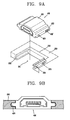
- FIGS. 9A and 9B are conceptual views of a socket module in accordance with a second exemplary embodiment
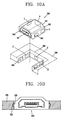
- FIGS. 10A and 10B are conceptual views of a socket module in accordance with a third exemplary embodiment
- FIGS. 11A and 11B are conceptual views of a socket module in accordance with a fourth exemplary embodiment.
- FIG. 12 is a conceptual view showing a state before the socket module according to the third or fourth exemplary embodiment is coupled to a carrier.
- Mobile terminals described in this specification may include cellular phones, smart phones, laptop computers, digital broadcasting terminals, personal digital assistants (PDAs), portable multimedia players (PMPs), navigators, and the like.
- PDAs personal digital assistants
- PMPs portable multimedia players
- navigators and the like.
- stationary terminals such as digital TV, desktop computers and the like excluding a case of being applicable only to the mobile terminals.
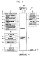
- FIG. 1 is a block diagram of a mobile terminal 100 in accordance with one exemplary embodiment.
- the mobile terminal 100 may comprise components, such as a wireless communication unit 110, an Audio/Video (A/V) input unit 120, a user input unit 130, a sensing unit 140, an output unit 150, a memory 160, an interface unit 170, a controller 180, a power supply 190 and the like.
- FIG. 1 shows the mobile terminal 100 having various components, but it is understood that implementing all of the illustrated components is not a requirement. Greater or fewer components may alternatively be implemented.
- the wireless communication unit 110 may typically include one or more modules which permit wireless communications between the mobile terminal 100 and a wireless communication system or between the mobile terminal 100 and a network within which the mobile terminal 100 is located.
- the wireless communication unit 110 may include a broadcast receiving module 111, a mobile communication module 112, a wireless Internet module 113, a short-range communication module 114, a location information module 115 and the like.
- the broadcast receiving module 111 receives a broadcast signal and/or broadcast associated information from an external broadcast managing entity via a broadcast channel.
- the broadcast channel may include a satellite channel and a terrestrial channel.
- the broadcast managing entity may indicate a server which generates and transmits a broadcast signal and/or broadcast associated information or a server which receives a pre-generated broadcast signal and/or broadcast associated information and sends them to the mobile terminal.
- the broadcast signal may be implemented as a TV broadcast signal, a radio broadcast signal, and a data broadcast signal, among others.
- the broadcast signal may further include a data broadcast signal combined with a TV or radio broadcast signal.
- broadcast associated information may include information associated with a broadcast channel, a broadcast program, a broadcast service provider, and the like.
- the broadcast associated information may be provided via a mobile communication network, and received by the mobile communication module 112.
- broadcast associated information may be implemented in various formats.
- broadcast associated information may include Electronic Program Guide (EPG) of Digital Multimedia Broadcasting (DMB), Electronic Service Guide (ESG) of Digital Video Broadcast-Handheld (DVB-H), and the like.
- EPG Electronic Program Guide
- DMB Digital Multimedia Broadcasting
- ESG Electronic Service Guide
- DVD-H Digital Video Broadcast-Handheld
- the broadcast receiving module 111 may be configured to receive digital broadcast signals transmitted from various types of broadcast systems. Such broadcast systems may include Digital Multimedia Broadcasting-Terrestrial (DMB-T), Digital Multimedia Broadcasting-Satellite (DMB-S), Media Forward Link Only (MediaFLO), Digital Video Broadcast-Handheld (DVB-H), Integrated Services Digital Broadcast-Terrestrial (ISDB-T) and the like.
- the broadcast receiving module 111 may be configured to be suitable for every broadcast system transmitting broadcast signals as well as the digital broadcasting systems.
- Broadcast signals and/or broadcast associated information received via the broadcast receiving module 111 may be stored in a suitable device, such as a memory 160.
- the mobile communication module 112 transmits/receives wireless signals to/from at least one of network entities (e.g., base station, an external mobile terminal, a server, etc.) on a mobile communication network.
- the wireless signals may include audio call signal, video (telephony) call signal, or various formats of data according to transmission/reception of text/multimedia messages.
- the wireless Internet module 113 supports wireless Internet access for the mobile terminal. This module may be internally or externally coupled to the mobile terminal 100. Examples of such wireless Internet access may include Wireless LAN (WLAN) (Wi-Fi), Wireless Broadband (Wibro), Worldwide Interoperability for Microwave Access (Wimax), High Speed Downlink Packet Access (HSDPA) and the like.
- WLAN Wireless LAN
- Wibro Wireless Broadband
- Wimax Worldwide Interoperability for Microwave Access
- HSDPA High Speed Downlink Packet Access
- the short-range communication module 114 denotes a module for short-range communications. Suitable technologies for implementing this module may include BLUETOOTHTM, Radio Frequency IDentification (RFID), Infrared Data Association (IrDA), Ultra-WideBand (UWB), ZigBeeTM, and the like.
- RFID Radio Frequency IDentification
- IrDA Infrared Data Association
- UWB Ultra-WideBand
- ZigBeeTM ZigBeeTM
- the location information module 115 denotes a module for detecting or calculating a position of a mobile terminal.
- An example of the location information module 115 may include a Global Position System (GPS) module.
- GPS Global Position System
- the A/V input unit 120 is configured to provide audio or video signal input to the mobile terminal.
- the AN input unit 120 may include a camera 121 and a microphone 122.
- the camera 121 receives and processes image frames of still pictures or video obtained by image sensors in a video call mode or a capturing mode. The processed image frames may be displayed on a display unit 151.
- the image frames processed by the camera 121 may be stored in the memory 160 or transmitted to the exterior via the wireless communication unit 110. Two or more cameras 121 may be provided according to the configuration of the mobile terminal.
- the microphone 122 may receive an external audio signal while the mobile terminal is in a particular mode, such as a phone call mode, a recording mode, a voice recognition mode, or the like. This audio signal is processed into digital data. The processed digital data is converted for output into a format transmittable to a mobile communication base station via the mobile communication module 112 in case of the phone call mode.
- the microphone 122 may include assorted noise removing algorithms to remove noise generated in the course of receiving the external audio signal.
- the user input unit 130 may generate input data input by a user to control the operation of the mobile terminal.
- the user input unit 130 may include a keypad, a dome switch, a touchpad (e.g., static pressure/capacitance), a jog wheel, a jog switch and the like.
- the sensing unit 140 provides status measurements of various aspects of the mobile terminal. For instance, the sensing unit 140 may detect an open/close status of the mobile terminal, a change in a location of the mobile terminal 100, a presence or absence of user contact with the mobile terminal 100, the location of the mobile terminal 100, acceleration/deceleration of the mobile terminal 100, and the like, so as to generate a sensing signal for controlling the operation of the mobile terminal 100. For example, regarding a slide-type mobile terminal, the sensing unit 140 may sense whether a sliding portion of the mobile terminal is open or closed. Other examples include sensing functions, such as the sensing unit 140 sensing the presence or absence of power provided by the power supply 190, the presence or absence of a coupling or other connection between the interface unit 170 and an external device. Meanwhile, the sensing unit 140 may include a proximity sensor 141.
- the output unit 150 is configured to output an audio signal, a video signal or a tactile signal.
- the output unit 150 may include a display unit 151, an audio output module 152, an alarm unit 153 and a haptic module 154.
- the display unit 151 may output information processed in the mobile terminal 100. For example, when the mobile terminal is operating in a phone call mode, the display unit 151 will provide a User Interface (UI) or a Graphic User Interface (GUI), which includes information associated with the call. As another example, if the mobile terminal is in a video call mode or a capturing mode, the display unit 151 may additionally or alternatively display images captured and/or received, UI, or GUI.
- UI User Interface
- GUI Graphic User Interface
- the display unit 151 may be implemented using, for example, at least one of a Liquid Crystal Display (LCD), a Thin Film Transistor-Liquid Crystal Display (TFT-LCD), an Organic Light-Emitting Diode (OLED), a flexible display, a three-dimensional (3D) display or the like.
- LCD Liquid Crystal Display
- TFT-LCD Thin Film Transistor-Liquid Crystal Display
- OLED Organic Light-Emitting Diode
- flexible display a three-dimensional (3D) display or the like.
- Some of such displays 151 may be implemented as a transparent type or an optical transparent type through which the exterior is visible, which is referred to as 'transparent display'.
- a representative example of the transparent display may include a Transparent OLED (TOLED), and the like.
- the rear surface of the display unit 151 may also be implemented to be optically transparent. Under this configuration, a user can view an object positioned at a rear side of a terminal body through a region occupied by the display unit 151 of the terminal body.
- the display unit 151 may be implemented in two or more in number according to a configured aspect of the mobile terminal 100. For instance, a plurality of the displays 151 may be arranged on one surface to be spaced apart from or integrated with each other, or may be arranged on different surfaces.
- the display unit 151 and a touch sensitive sensor have a layered structure therebetween, the structure may be referred to as a touch screen.
- the display unit 151 may be used as an input device rather than an output device.
- the touch sensor may be implemented as a touch film, a touch sheet, a touchpad, and the like.
- the touch sensor may be configured to convert changes of a pressure applied to a specific part of the display unit 151, or a capacitance occurring from a specific part of the display unit 151, into electric input signals. Also, the touch sensor may be configured to sense not only a touched position and a touched area, but also touch pressure.
- touch controller When touch inputs are sensed by the touch sensors, corresponding signals are transmitted to a touch controller.
- the touch controller processes the received signals, and then transmits corresponding data to the controller 180. Accordingly, the controller 180 may sense which region of the display unit 151 has been touched.
- a proximity sensor 141 may be arranged at an inner region of the mobile terminal 100 covered by the touch screen, or near the touch screen.
- the proximity sensor 141 indicates a sensor to sense presence or absence of an object approaching to a surface to be sensed, or an object disposed near a surface to be sensed, by using an electromagnetic field or infrared rays without a mechanical contact.
- the proximity sensor 141 has a longer lifespan and a more enhanced utility than a contact sensor.
- the proximity sensor 141 may include a transmissive type photoelectric sensor, a direct reflective type photoelectric sensor, a mirror reflective type photoelectric sensor, a high-frequency oscillation proximity sensor, a capacitance type proximity sensor, a magnetic type proximity sensor, an infrared rays proximity sensor, and so on.
- a capacitance type proximity sensor When the touch screen is implemented as a capacitance type, proximity of a pointer to the touch screen is sensed by changes of an electromagnetic field.
- the touch screen may be categorized into a proximity sensor.
- a status that the pointer is positioned to be proximate onto the touch screen without contact will be referred to as 'proximity touch'
- a status that the pointer substantially comes in contact with the touch screen will be referred to as 'contact touch'.
- 'proximity touch' a status that the pointer substantially comes in contact with the touch screen.
- the proximity sensor 141 senses proximity touch, and proximity touch patterns (e.g., distance, direction, speed, time, position, moving status, etc.). Information relating to the sensed proximity touch and the sensed proximity touch patterns may be output onto the touch screen.
- proximity touch patterns e.g., distance, direction, speed, time, position, moving status, etc.
- the audio output module 152 may output audio data received from the wireless communication unit 110 or stored in the memory 160, in a call-receiving mode, a call-placing mode, a recording mode, a voice recognition mode, a broadcast reception mode, and so on.
- the audio output module 152 may output audio signals relating to functions performed in the mobile terminal 100, e.g., sound alarming a call received or a message received, and so on.
- the audio output module 152 may include a receiver, a speaker, a buzzer, and so on.
- the alarm unit 153 outputs signals notifying occurrence of events from the mobile terminal 100.
- the events occurring from the mobile terminal 100 may include call received, message received, key signal input, touch input, and so on.
- the alarm unit 153 may output not only video or audio signals, but also other types of signals such as signals notifying occurrence of events in a vibration manner. Since the video or audio signals can be output through the display unit 151 or the audio output module 152, the display unit 151 and the audio output module 152 may be categorized into a part of the alarm unit 153.
- the haptic module 154 generates various tactile effects which a user can feel.
- a representative example of the tactile effects generated by the haptic module 154 includes vibration.
- Vibration generated by the haptic module 154 may have a controllable intensity, a controllable pattern, and so on. For instance, different vibration may be output in a synthesized manner or in a sequential manner.
- the haptic module 154 may generate various tactile effects, including not only vibration, but also arrangement of pins vertically moving with respect to a skin being touched (contacted), air injection force or air suction force through an injection hole or a suction hole, touch by a skin surface, presence or absence of contact with an electrode, effects by stimulus such as an electrostatic force, reproduction of cold or hot feeling using a heat absorbing device or a heat emitting device, and the like.
- the haptic module 154 may be configured to transmit tactile effects (signals) through a user's direct contact, or a user's muscular sense using a finger or a hand.
- the haptic module 154 may be implemented in two or more in number according to the configuration of the mobile terminal 100.
- the memory 160 may store a program for the processing and control of the controller 180. Alternatively, the memory 160 may temporarily store input/output data (e.g., phonebook data, messages, still images, video and the like). Also, the memory 160 may store data related to various patterns of vibrations and audio output upon the touch input on the touch screen.
- input/output data e.g., phonebook data, messages, still images, video and the like.
- the memory 160 may store data related to various patterns of vibrations and audio output upon the touch input on the touch screen.
- the memory 160 may be implemented using any type of suitable storage medium including a flash memory type, a hard disk type, a multimedia card micro type, a memory card type (e.g., SD or DX memory), Random Access Memory (RAM), Static Random Access Memory (SRAM), Read-Only Memory (ROM), Electrically Erasable Programmable Read-Only Memory (EEPROM), Programmable Read-Only Memory (PROM), magnetic memory, magnetic disk, optical disk, and the like.
- the mobile terminal 100 may operate a web storage which performs the storage function of the memory 160 on the Internet.
- the interface unit 170 may generally be implemented to interface the mobile terminal with external devices.
- the interface unit 170 may allow a data reception from an external device, a power delivery to each component in the mobile terminal 100, or a data transmission from the mobile terminal 100 to an external device.
- the interface unit 170 may include, for example, wired/wireless headset ports, external charger ports, wired/wireless data ports, memory card ports, ports for coupling devices having an identification module, audio Input/Output (I/O) ports, video I/O ports, earphone ports, and the like.
- I/O audio Input/Output
- the identification module may be configured as a chip for storing various information required to authenticate an authority to use the mobile terminal 100, which may include a User Identity Module (UIM), a Subscriber Identity Module (SIM), and the like. Also, the device having the identification module (hereinafter, referred to as 'identification device') may be implemented in a type of smart card. Hence, the identification device can be coupled to the mobile terminal 100 via a port.
- UIM User Identity Module
- SIM Subscriber Identity Module
- the interface unit 170 may serve as a path for power to be supplied from an external cradle to the mobile terminal 100 when the mobile terminal 100 is connected to the external cradle or as a path for transferring various command signals input from the cradle by a user to the mobile terminal 100.
- Such various command signals or power input from the cradle may operate as signals for recognizing that the mobile terminal 100 has accurately been mounted to the cradle.
- the controller 180 typically controls the overall operations of the mobile terminal 100. For example, the controller 180 performs the control and processing associated with telephony calls, data communications, video calls, and the like.
- the controller 180 may include a multimedia module 181 which provides multimedia playback.
- the multimedia module 181 may be configured as part of the controller 180 or as a separate component.
- the controller 180 can perform a pattern recognition processing so as to recognize writing or drawing input on the touch screen as text or image.
- the power supply 190 provides power required by various components under the control of the controller 180.
- the provided power may be internal power, external power, or combination thereof.
- the embodiments described herein may be implemented within one or more Application Specific Integrated Circuits (ASICs), Digital Signal Processors (DSPs), Digital Signal Processing Devices (DSPDs), Programmable Logic Devices (PLDs), Field Programmable Gate Arrays (FPGAs), processors, microprocessors, other electronic units designed to perform the functions described herein, or a selective combination thereof. In some cases, such embodiments are implemented by the controller 180.
- ASICs Application Specific Integrated Circuits
- DSPs Digital Signal Processors
- DSPDs Digital Signal Processing Devices
- PLDs Programmable Logic Devices
- FPGAs Field Programmable Gate Arrays
- processors microprocessors, other electronic units designed to perform the functions described herein, or a selective combination thereof.
- microprocessors other electronic units designed to perform the functions described herein, or a selective combination thereof.
- the software codes can be implemented with a software application written in any suitable programming language. Also, the software codes may be stored in the memory 160 and executed by the controller 180.
- FIG. 2 is a front perspective view showing an example of the mobile terminal
- FIG. 3 is a rear perspective of the mobile terminal of FIG. 2 .
- the mobile terminal 100 disclosed herein is provided with a bar-type terminal body.
- the present application is not limited to this type of terminal, but is also applicable to various structures of terminals such as slide type, folder type, swivel type, swing type, and the like, in which two or more bodies are combined with each other in a relatively movable manner.
- the mobile terminal described herein may be applied to random portable electronic devices having a camera and a flash, for example, a cellular phone, a smart phone, a notebook computer, a digital broadcasting terminal, Personal Digital Assistants (PDA), Portable Multimedia Player (PMO) and the like.
- PDA Personal Digital Assistants
- PMO Portable Multimedia Player
- the terminal body may include a case (or referred to as casing, housing, cover, etc.) defining an appearance of the mobile terminal 100.
- the case may be divided into a front case 201 and a rear case 202.
- a space formed between the front and rear cases 201 and 202 may accommodate various electronic components.
- Such cases may be injected using a synthetic resin or be formed of a metal, such as stainless steel (STS), titanium (Ti) or the like.
- a rear surface of the terminal body may be shown having a power supply unit 222, a rear camera 221 and a second audio output module 225.
- the power supply unit 222 may supply power to the mobile terminal 100.
- the power supply unit 222 may be mounted in the terminal body or detachably coupled directly onto the outside of the terminal body.
- a flash 223 may be disposed adjacent to the rear camera 221.
- the flash 223 operates in conjunction with the rear camera 221 when taking a picture using the rear camera 221.
- a mirror 224 may be disposed adjacent to the flash 224.
- the mirror 224 can cooperate with the rear camera 221 to allow a user to photograph himself in a self-portrait mode.
- the second audio output module 225 may cooperate with a first audio output module 211, which is disposed on the front surface of the terminal body, to provide stereo output. Also, the second audio output module 225 may be configured to operate as a speakerphone.
- the rear camera 221 faces a direction which is opposite to a direction faced by a front camera 211 disposed on the front surface of the terminal body, and may have different pixels from those of the rear camera 221.
- the front camera 216 may operate with relatively lower pixels (lower resolution).
- the front camera 216 may be useful when a user can capture his face and send it to another party during a video call or the like.
- the rear camera 221 may operate with relatively higher pixels (higher resolution) such that it can be useful for a user to obtain higher quality pictures for later use.
- the front and rear cameras 216 and 221 may be installed in the terminal body to be rotatable or popped up.
- the front surface of the terminal body may be shown having a display module 210, a first audio output module 211, a signal input unit 230 and a front camera 216.
- the display module 210 may output visual information. Examples of the display module 210 may include a Liquid Crystal Display (LCD) module, an Organic Light Emitting Diodes (OLED) module, an e-paper and the like.
- the display module 210 may include a touch sensor for allowing a touch input. When the touch sensor senses a touch input on a specific point on the display module 210, a content corresponding to the touched point may be input. Contents input by the touch manner may include text or numerals or menu items which are instructed or selected in various modes.
- the touch sensor may be transparent such that the display module 210 can be viewed, and have a structure for enhancing visibility of a touch screen at a bright place. In FIG. 2 , the display module 210 may occupy most of the front surface of the front case 201.
- the first audio output module 211 may be implemented as a receiver to transfer a call sound to a user's ear, or a loud speaker for outputting various alarm sounds or multimedia reproduction sounds.
- the front camera 216 may receive and process image frames of still pictures or video obtained by image sensors in a video call mode or a capturing mode.
- the processed image frames may be displayed on a display unit 151.
- the image frames processed in the front camera 216 may be stored in the memory 160 or transmitted to the exterior via the wireless communication unit 110.
- the front camera 216 may be provided by more than two according to usage environments.
- the signal input unit 230 may be manipulated to allow inputting of commands for controlling operations of the mobile terminal 100, and include a plurality of input keys.
- the plurality of input keys may be referred to as a manipulating portion.
- Such manipulating portion can employ any tactile manner that a user can touch or tap for manipulation.
- the signal input unit 230 may be implemented as a dome switch, a touch screen or a touch pad, which allows a user to input commands or information in a pushing or touching manner, or as a wheel for rotating keys or a jog or joystick.
- Contents input via the signal input unit 230 may be set variously, for example, to input START, END, SCROLL or the like.
- a side surface of the front case 201 may be shown having a side key 214, interfaces 212, 225, an audio input unit 213 and the like.
- the side key 214 may be referred to as a manipulating unit, and be configured to receive a command for controlling an operation of a mobile terminal 200.
- the side key 214 may employ any tactile manner that a user can touch or tap for manipulation. Contents input via the side key 214 may be set variously.
- the side key 214 may receive commands, such as adjusting a volume of sound output via the audio output module 211, 225, converting into a touch recognition mode of the display unit 210, and the like.
- the audio (sound) input unit 213 may be implemented as a microphone for receiving user's voice, other sound and the like.
- the interface unit 215, 225 may serve as a path for data exchange between a mobile terminal 200 and external devices.
- the interface unit 215, 225 may be at least one of wired/wireless earphone ports, ports for short-range communication (e.g., IrDA, Bluetooth, WLAN, etc.), power supply terminals for power supply to the mobile terminal and the like.
- the interface unit 215, 225 may be a card socket for coupling to external cards, such as a Subscriber Identity Module (SIM), a User Identity Module (UIM), a memory card for storage of information and the like.
- SIM Subscriber Identity Module
- UIM User Identity Module
- the mobile terminal 200 may include an interface unit implemented as a socket module 300 (see FIG. 4 ).
- a plug 10 may be inserted into the socket module 300, for allowing transmission and reception of signals.
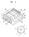
- FIG. 4 is a perspective view of a socket module in accordance with a first exemplary embodiment
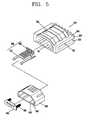
- FIG. 5 is a disassembled perspective view of FIG. 4 .
- the socket module 300 may include a housing 310, and a coupling unit 320.
- An insulating member 340 (see FIG. 5 ) may be formed on an inner circumferential surface of the housing 310.
- a pin 330 connected to the plug 10 may be mounted in an inner space of the housing 310.
- the housing 310 may be formed in a polyhedral shape.
- the housing 310 may be formed to cover every surface of the socket module 300 except for one surface having an opening 311, and surround an inner space of the socket module 300.
- the housing 310 may be made of a metal or synthetic resin, and the pin 330 may be formed of a conductive material. When the housing 310 is formed of the synthetic resin, it may be formed in a molding manner.
- one surface of the socket module 300 having the opening 311 is referred to as a first surface 1, an opposite surface facing the opening 311 is referred to as a second surface 2, the other side surfaces except for the first surface 1 and the second surface 2 are referred to as a third surface 3 and a fourth surface 4, and upper and lower surfaces of the socket module 300 except for those side surfaces are referred to as a fifth surface 5 and a sixth surface 6.
- the coupling unit 320 may be formed on at least one side, for example, the third surface 3 or the fourth surface 4 of the housing 310, or on both sides of the housing 310.
- the coupling unit 320 may be formed such that the socket module 300 is coupled to a substrate 240 when the socket module 300 is slid with respect to the substrate 240.
- the sliding direction may be a direction from one side end of the substrate 240 to a central portion thereof.
- the socket module 300 is generally mounted to cover the substrate 240.
- the substrate 240 may have a part cut off to form an open space 241 (see FIG. 6A ), and the socket module 300 may be slid into the open space 241 to be coupled to the substrate 240.
- the open space 241 of the substrate 240 may correspond to a size of a section of the socket module 300.
- the substrate 240 may have a portion, which is recessed from one side thereof into its inside by a predetermined interval.
- the socket module 300 may be coupled to the substrate 240 by virtue of a groove member 322 or a protrusion member 422 (see FIG. 9A ) on the socket module 300.
- the groove member 322 or protrusion member 422 may be formed on the substrate 240.
- a coupling using an adhesive or a coupling using a piece may be implemented.
- the substrate 240 may include a module mounting unit 242 to which the socket module 300 is mounted.
- the module mounting unit 242 may be formed at an adjacent portion to the open space 241 of the substrate 240, which is formed to correspond to the section of the socket module 300.
- a terminal portion 243 may be formed on the module mounting portion 242.
- the terminal portion 243 may be coupled to a second pin 332.
- the socket module 300 may further include a cover 350 for opening or closing the opening 311.
- the socket module 300 may also include a guide portion 342 for guiding the motion of the cover 350, and a locking protrusion 341 for preventing separation between the cover 350 and the housing 310.
- the cover 350 may have a shape corresponding to the section of the opening 311. When the plug 10 is inserted, the cover 350 may be slid into the socket module 300 along the guide portion 342.
- the cover 350 may be connected to elastic support units 351 to close the opening 311 when the plug 10 is removed.
- the elastic support unit 351 may have one end connected to the cover 350, and the other end connected to one side surface of the inner space, which faces the cover 350.
- the socket module 300 may include a first pin 331 formed within the socket module 300, and a second pin(s) 332 extending to the outside of the socket module 300.
- the first pin 331 may be electrically connected to the plug 10, and disposed within the housing 310.
- the second pin 332 may be connected to the first pin 331 and extend to the outside of the housing 310 so that the other end thereof can be connected to the terminal portion 243 of the substrate 240.
- the second pin 332 may extend in an opposite direction to the opening 311 formed at the housing 310, so as to be connected to the terminal portion 243 of the substrate 240.
- the coupling unit 320 may include a groove member 322 or a protrusion member 422 corresponding to the shape of the substrate 240. As shown in FIG. 3 , the first exemplary embodiment has illustrated that the coupling unit 320 includes the groove member 322, but a second exemplary embodiment (see FIG. 9A ) illustrates that the coupling unit 320 includes the protrusion member 422.
- the coupling unit 320 may include the groove member 322.
- the groove member 322 may be a part of the coupling unit 320 for defining (limiting) a groove 321 in which the part of the substrate 240 is inserted.
- the groove 321 has a width approximately the same as a thickness of the substrate 240
- the substrate 240 may be engaged with the groove member 322 upon insertion.
- the recess may be formed so that its width can gradually increase or decrease toward any one side. Accordingly, when the socket module 300 is slid, the recess may increase a frictional force to restrict the sliding of the socket module 300 when the socket module 300 is slid up to a predetermined position.
- the coupling unit 320 may include an extension member 323 which extends toward the substrate 240 to cover an inserted portion of the substrate 240 when the substrate 240 is partially inserted into the groove 321.
- the extension member 323 may have a predetermined length to cover the upper surface and the lower surface of the substrate 240, thereby allowing more stable coupling between the socket module 300 and the substrate 240.
- the coupling unit 320 and the substrate 240 may include a lock portion 324 and a stopping portion 244, by which the socket module 300 and the substrate 240 are fixed in the coupled state.
- the stopping portion 244 may be formed on the other of the socket module 300 and the substrate 240.
- the lock portion 324 may be a protrusion protruding to the outside, and the stopping portion 244 may be a portion recessed inwardly so that the lock portion 324 is locked therein.
- the lock portion 324 may be elastically transformed such that the socket module 300 can be detachably coupled to the substrate 240.
- FIGS. 6A to 6C are views each showing a coupled state between the socket module and a substrate.
- FIG. 6A shows a state before the socket module 300 is coupled to the substrate 240
- FIG. 6B shows a coupled state between the socket module 300 and the substrate 240
- FIG. 6C is a sectional view in the coupled state between the socket module 300 and the substrate 240.
- the socket module 300 may be slid toward the module mounting unit 242 which is the partially open portion of the substrate 240.
- the groove member 322 may contact the substrate 240, and then the substrate 240 may be inserted into the groove 321 limited by the groove member 322.
- the socket module 300 When the socket module 300 is slid into the substrate 240 by a predetermined depth, the socket module 300 may be fixed by a frictional force between the groove member 322 and the substrate 240.
- a substrate assembly that the socket module 300 and the substrate 240 are coupled to each other may include the lock portion 324 and the stopping portion 244. With the socket module 300 and the substrate 240 coupled to each other, the lock portion 324 may contact the stopping portion 244, fixing the socket module 300 to the substrate 240.
- the substrate assembly that the socket module 300 and the substrate 240 are coupled to each other may become slimmer by a thickness of the substrate 240.
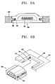
- FIG. 7 is a conceptual view showing a variation of a pin shown in FIG. 5
- FIGS. 8A and 8B are conceptual views showing a variation of the socket module of FIG. 4 according to the shape of the varied pin of FIG. 7 .
- a first pin 331' formed within the housing 310 may be connected to the plug 10, and a second pin 332' formed on the outside of the housing 310 may extend in a different direction (e.g., toward the third or fourth surface) from the first exemplary embodiment (e.g., toward the second surface).
- the second pin 332 may extend toward the second surface, as the opposite side to the position of the opening 311 of the housing 310.
- the second pin 332' may extend toward at least one side surface, namely, toward the third surface 3 or the fourth surface 4.
- the second pin 332' may extend toward one side surface of the housing 310 and penetrate through the groove member 322.
- a terminal portion 243' electrically connected to the second pin 332' may be formed on one side surface of the substrate 240 inserted into the coupling unit 320.
- the socket module 300 may be coupled to the substrate 240 in the sliding manner. This may allow the second pin 332' to be connected to the terminal portion 243'.
- the coupling unit 320 and the substrate 240 may include a lock portion 324 or a stopping portion 244.
- FIGS. 9A and 9B are conceptual views of a socket module 400 in accordance with a second exemplary embodiment.
- FIG. 9A shows a state before the socket module 400 is coupled to a substrate 250
- FIG. 9B shows the coupled state between the socket module 400 and the substrate 250.
- a housing 410, a cover 450 and a pin according to this exemplary embodiment will also be understood by the description given of those components in the first exemplary embodiment and the varied embodiment.
- a coupling unit 420 may include a protrusion member 422 protruding toward the substrate 250.
- a groove portion 255 may be formed at the substrate 250 in correspondence with the protrusion member 422.
- the substrate 250 may include a module mounting unit 252 to which the socket module 400 is mounted.
- the module mounting unit 252 may be formed at a portion adjacent to an open area of the substrate 250, which is formed by cutting off a part of the substrate 250 to correspond to the section of the socket module 400.
- the groove portion 255 may be formed along an inner circumferential surface of the module mounting unit 252.
- the socket module 400 When the protrusion member 422 of the socket module 400 is slidably inserted into the groove portion 255 of the substrate 250, the socket module 400 may be coupled to the substrate 250. This may result in reducing a thickness of the substrate assembly having the socket module 400 by the thickness of the substrate 250.
- a second pin 432' may extend toward at least one side surface of the housing 410.
- the second pin 432' may protrude through the protrusion member 422 to be electrically connected to terminal portion 253 formed on the groove portion 255.
- FIGS. 10A and 10B are conceptual views of a socket module 500 in accordance with a third exemplary embodiment.
- FIG. 10A shows a state before the socket module 500 is coupled to a substrate 260
- FIG. 10B shows the coupled state between the socket module 500 and the substrate 260.
- a housing 510, a cover 550 and a pin according to this exemplary embodiment will also be understood by the description given of those components in the first exemplary embodiment and the exemplary variation.
- a second pin when an opening 511 is viewed at front, a second pin may be formed on a second surface 2 facing the first surface 1 of the housing 510 having the opening 511, an upper surface of the housing 510, or the third or fourth surface 3 or 4 corresponding to at least one side surface of the housing 510. That is, when the second pin is located on an area A, an area B or an area C, a terminal portion may be formed at a corresponding area A', B' or C' on the substrate 260.
- a coupling unit 520 may include a protrusion member 522 protruding in a lateral direction.
- the protrusion member 522 may be elastically transformable.
- the substrate 260 may include a recess portion 265 corresponding to the protrusion member 522.
- the socket module 500 according to the third exemplary embodiment may be slid in a direction penetrating through the substrate 260, unlike the previous exemplary embodiments, thereby being coupled to the substrate 260.
- FIGS. 11A and 11B are conceptual views of a socket module 600 in accordance with a fourth exemplary embodiment.
- FIG. 11A shows a state before the socket module 600 is coupled to a substrate 270
- FIG. 10B shows the coupled state between the socket module 600 and the substrate 270.
- a housing 610, a cover 650 and a pin according to this exemplary embodiment will also be understood by the description given of those components in the first exemplary embodiment and the exemplary variation.
- a second pin when an opening 611 is viewed at front, a second pin may be formed on a second surface 2 facing the first surface 1 of the housing 610 having the opening 611, an upper surface of the housing 610, or the third or fourth surface 3 or 4 corresponding to at least one side surface of the housing 610. That is, when the second pin is located on an area A, an area B or an area C, a terminal portion may be formed at a corresponding area A', B' or C' on the substrate 260.
- a coupling unit 620 may include a recess member 622 recessed inwardly from a side surface of the housing 610.
- the substrate 270 may include an elastic protrusion portion 275.
- the elastic protrusion portion 275 may protrude toward the recess member 622 to be elastically transformable.
- the socket module 600 according to the fourth exemplary embodiment may be slidable in a direction penetrating through the substrate 270, unlike the previous exemplary embodiments, thereby being coupled to the substrate 270.
- the elastic protrusion portion 275 may temporarily move toward the substrate 270 and be charged with an elastic energy. Then, when the sliding of the socket module 600 is completed, the elastic protrusion portion 275 may move toward the recess member 622 by discharging the charged elastic energy, to be coupled to the recess member 622.
- the elastic protrusion portion 275 may include a base member having one end fixed to the substrate 270, and an extension member extending from the base member by a predetermined angle.
- a hook member may be formed at an end of the extension member may be fixedly coupled to a fixing groove formed at the recess member 622.
- FIG. 12 is a conceptual view showing a state before the socket module 500, 600 according to the third or fourth exemplary embodiment is coupled to a carrier 281.
- the carrier 281 may have one surface with radiation patterns of an antenna and include a dielectric substance.
- the carrier 281 may have a predetermined volume in view of feature of an antenna. Accordingly, it may make it difficult to reduce a size of a mobile terminal. Therefore, when the socket module 500, 600 is mounted to the carrier 281, it may allow for more efficient use of a space of the mobile terminal.
- the carrier 281 may include a hole or groove 282 in which the socket module 500, 600 can be mounted.
- a terminal portion may be formed at at least one side of the hole or groove 282 to be coupled to the pin of the socket module 500, 600.
- the terminal portion may be electrically connected up to a circuit board 280.
- the carrier 281 may also include a communication hole 283 communicating with the opening of the socket module 500, 600.
- the socket module 500, 600 may be slidably mounted in the hole or groove 282 and electrically connected to the terminal portion.
- An elastic protrusion portion or a recess portion described in the third to fourth exemplary embodiments may be formed on one side surface of the hole or recess 282. This may be used to fix the socket module 500, 600 when the socket module is slidably mounted.
Landscapes
- Engineering & Computer Science (AREA)
- Signal Processing (AREA)
- Computer Networks & Wireless Communication (AREA)
- Manufacturing & Machinery (AREA)
- Microelectronics & Electronic Packaging (AREA)
- Telephone Set Structure (AREA)
Applications Claiming Priority (1)
| Application Number | Priority Date | Filing Date | Title |
|---|---|---|---|
| KR1020110129763A KR101923472B1 (ko) | 2011-12-06 | 2011-12-06 | 소켓 모듈 및 이를 구비한 단말기 |
Publications (2)
| Publication Number | Publication Date |
|---|---|
| EP2602973A1 true EP2602973A1 (de) | 2013-06-12 |
| EP2602973B1 EP2602973B1 (de) | 2014-07-16 |
Family
ID=47520655
Family Applications (1)
| Application Number | Title | Priority Date | Filing Date |
|---|---|---|---|
| EP12008045.2A Not-in-force EP2602973B1 (de) | 2011-12-06 | 2012-11-30 | Sockelmodul und tragbares Endgerät |
Country Status (3)
| Country | Link |
|---|---|
| US (1) | US8932069B2 (de) |
| EP (1) | EP2602973B1 (de) |
| KR (1) | KR101923472B1 (de) |
Cited By (2)
| Publication number | Priority date | Publication date | Assignee | Title |
|---|---|---|---|---|
| EP2911031A3 (de) * | 2014-02-21 | 2015-10-14 | Samsung Electronics Co., Ltd | Elektronische Vorrichtung und elektronische Vorrichtung in einer Abdeckung |
| KR20170044527A (ko) * | 2015-10-15 | 2017-04-25 | 삼성전자주식회사 | 케이스 및 이를 포함하는 전자 장치 |
Families Citing this family (10)
| Publication number | Priority date | Publication date | Assignee | Title |
|---|---|---|---|---|
| KR101923472B1 (ko) * | 2011-12-06 | 2018-11-29 | 엘지전자 주식회사 | 소켓 모듈 및 이를 구비한 단말기 |
| KR102037931B1 (ko) * | 2013-03-15 | 2019-11-26 | 엘지전자 주식회사 | 연결 모듈 및 이를 구비하는 이동 단말기 |
| US9942655B2 (en) * | 2013-09-20 | 2018-04-10 | Infineon Technologies Ag | Sound processing |
| JP6968545B2 (ja) * | 2017-02-01 | 2021-11-17 | オムロン株式会社 | 近接センサ |
| US10868375B2 (en) * | 2017-07-07 | 2020-12-15 | J.S.T. Corporation | Non-staggered dual Row SMT connector |
| CN108321566A (zh) * | 2018-01-17 | 2018-07-24 | 番禺得意精密电子工业有限公司 | 电连接器 |
| US10811798B2 (en) * | 2018-11-08 | 2020-10-20 | Te Connectivity Corporation | Card edge cable connector assembly |
| KR102054441B1 (ko) * | 2019-03-28 | 2019-12-10 | 주식회사 빌드잇 | 센서를 선택적으로 결합 가능한 비콘 장치 및 센서를 선택적으로 결합 가능한 비콘 장치를 통해 센싱 데이터를 전송하는 방법 |
| PL241248B1 (pl) * | 2019-07-17 | 2022-08-29 | Krzysztof Zieliński | Ramka rozszerzeń urządzeń mobilnych |
| KR102721676B1 (ko) * | 2020-07-27 | 2024-10-23 | 주식회사 엘지에너지솔루션 | 압력 측정 유닛 및 배터리 검사 장치 |
Citations (2)
| Publication number | Priority date | Publication date | Assignee | Title |
|---|---|---|---|---|
| WO1989007849A1 (en) * | 1988-02-15 | 1989-08-24 | Itt Industries Limited | Terminating insulated conductors |
| EP0920167A2 (de) * | 1997-11-28 | 1999-06-02 | Nokia Mobile Phones Ltd. | Gerät mit einer Buchse für Kopfhörer |
Family Cites Families (108)
| Publication number | Priority date | Publication date | Assignee | Title |
|---|---|---|---|---|
| US3745510A (en) * | 1971-07-02 | 1973-07-10 | Interdyne Co | Printed circuit board/integrated circuit socket combination |
| US4080522A (en) * | 1976-06-10 | 1978-03-21 | Cutler-Hammer, Inc. | Snap-in arrangement for mounting devices in a support panel aperture |
| GB8510839D0 (en) | 1985-04-29 | 1985-06-05 | Allied Corp | Electric circuit board assembly |
| GB8510840D0 (en) * | 1985-04-29 | 1985-06-05 | Allied Corp | Electrical connectors |
| US4695112A (en) * | 1986-12-29 | 1987-09-22 | Chrysler Motors Corporation | Printed circuit board, edgeboard connector therefor |
| US4997996A (en) * | 1987-12-17 | 1991-03-05 | Nihon Kaikeiki Kogyo Kabushiki Kaisha | Printed wiring board mounted electronic component |
| JPH0546227Y2 (de) * | 1988-04-25 | 1993-12-02 | ||
| JPH0737333Y2 (ja) * | 1989-06-13 | 1995-08-23 | ティアツク株式会社 | 部品取付け用ホルダー |
| US5160275A (en) * | 1990-09-06 | 1992-11-03 | Hirose Electric Co., Ltd. | Electrical connector for circuit boards |
| US5184961A (en) * | 1991-06-20 | 1993-02-09 | Burndy Corporation | Modular connector frame |
| US5277596A (en) * | 1992-12-16 | 1994-01-11 | The Whitaker Corporation | Method of producing a card edge mounted connector and the resulting assembly thereof |
| US5755586A (en) * | 1995-06-07 | 1998-05-26 | Maxtor Corporation | PCMCIA strain relieved electrical connector assembly |
| US5702271A (en) * | 1996-08-30 | 1997-12-30 | The Whitaker Corporation | Ultra low profile board-mounted modular jack |
| US5944536A (en) * | 1996-10-31 | 1999-08-31 | Thomas & Betts Corporation | Cover for an edge mounted printed circuit board connector |
| US5881454A (en) * | 1996-11-25 | 1999-03-16 | Seagate Technology, Inc. | Method of making single-sided electronic connector |
| EP0848459B1 (de) * | 1996-12-13 | 2006-10-11 | FUBA Automotive GmbH & Co. KG | Leitungs-Steckverbindung |
| JP3594434B2 (ja) * | 1997-01-08 | 2004-12-02 | ヒロセ電機株式会社 | 回路基板への電気コネクタ取付構造 |
| US6315620B1 (en) * | 1997-04-24 | 2001-11-13 | Seagate Technology Llc | System, method, and device for a pre-loaded straddle mounted connector assembly |
| TW420404U (en) * | 1998-07-28 | 2001-01-21 | Hon Hai Prec Ind Co Ltd | Mini-connector |
| US6227872B1 (en) * | 1998-08-05 | 2001-05-08 | Ericsson Inc. | Moisture resistant electrical connector for a cellular telephone |
| TW422451U (en) * | 1998-09-22 | 2001-02-11 | Hon Hai Prec Ind Co Ltd | Power connector |
| TW389394U (en) * | 1998-10-23 | 2000-05-01 | Hon Hai Prec Ind Co Ltd | Electrical connector |
| TW379878U (en) * | 1998-12-18 | 2000-01-11 | Speed Tech Corp | Clamping plate type memory card connector |
| JP3445944B2 (ja) * | 1999-03-30 | 2003-09-16 | シャープ株式会社 | ジャック式光電共用接続装置 |
| JP3393839B2 (ja) * | 2000-02-03 | 2003-04-07 | 株式会社日本ディックス | コネクタ |
| US6325674B1 (en) * | 2000-03-20 | 2001-12-04 | 3Com Corporation | Card edge connector for a modular jack |
| TW481380U (en) * | 2000-12-21 | 2002-03-21 | Hon Hai Prec Ind Co Ltd | Board-sinking type electrical connector |
| TW502883U (en) * | 2000-12-29 | 2002-09-11 | Hon Hai Prec Ind Co Ltd | Electrical connector |
| US6416358B1 (en) * | 2001-04-23 | 2002-07-09 | Molex Incorporated | Shielded electrical connector for mounting on a printed circuit board |
| TW560241B (en) * | 2001-05-18 | 2003-11-01 | Hosiden Corp | Printed circuit board mounted connector |
| TW493828U (en) * | 2001-06-13 | 2002-07-01 | Hon Hai Prec Ind Co Ltd | Socket connector |
| US20030003783A1 (en) * | 2001-06-29 | 2003-01-02 | Sung-Ming Song | Replaceable module for a notebook computer |
| JP2005521183A (ja) * | 2001-07-02 | 2005-07-14 | シーゲイト テクノロジー エルエルシー | ディスクドライブ回路盤用エッジコネクタ |
| JP2003031316A (ja) * | 2001-07-18 | 2003-01-31 | Jst Mfg Co Ltd | 誤嵌合防止コネクタ |
| TW514346U (en) * | 2002-03-08 | 2002-12-11 | Molex Inc | Electric connector and fixture structure for circuit board |
| TW545736U (en) * | 2002-05-01 | 2003-08-01 | Molex Inc | Electrical connector |
| JP3801546B2 (ja) * | 2002-08-07 | 2006-07-26 | Smk株式会社 | スイッチ付き同軸コネクタ |
| US6666694B1 (en) * | 2002-08-21 | 2003-12-23 | Methode Electronics, Inc. | Reduced profile EMI receptacle assembly |
| US6824429B2 (en) * | 2002-10-17 | 2004-11-30 | Hon Hai Precision Ind. Co., Ltd. | Transceiver cage assembly |
| TW555209U (en) * | 2002-12-24 | 2003-09-21 | Molex Taiwan Ltd | Electrical connector |
| US6692273B1 (en) * | 2002-12-31 | 2004-02-17 | Hon Hai Precision Ind. Co., Ltd. | Straddle mount connector |
| JP4181895B2 (ja) * | 2003-02-25 | 2008-11-19 | 日本圧着端子製造株式会社 | リセプタクル |
| TW570390U (en) * | 2003-03-12 | 2004-01-01 | Hon Hai Prec Ind Co Ltd | Electrical connector |
| TW568418U (en) * | 2003-05-26 | 2003-12-21 | Speed Tech Corp | Shield housing of connector |
| JP2005056626A (ja) * | 2003-07-31 | 2005-03-03 | Mitsumi Electric Co Ltd | シャッタ付きコネクタ |
| TWM254780U (en) * | 2003-12-09 | 2005-01-01 | Hon Hai Prec Ind Co Ltd | Electrical connector |
| US20050233602A1 (en) * | 2004-04-19 | 2005-10-20 | Link Michael A | Serial advanced technology attachment connector that can be mounted on an edge of a printed circuit board |
| CN2791967Y (zh) * | 2005-03-25 | 2006-06-28 | 富士康(昆山)电脑接插件有限公司 | 电连接器 |
| CN100448114C (zh) * | 2005-04-19 | 2008-12-31 | 富士康(昆山)电脑接插件有限公司 | 电连接器 |
| TWM290333U (en) * | 2005-11-18 | 2006-05-01 | Advanced Connectek Inc | Sink-board type electric connector |
| KR101236391B1 (ko) * | 2005-12-01 | 2013-02-22 | 삼성전자주식회사 | 정보처리장치 |
| TWM305483U (en) * | 2006-08-16 | 2007-01-21 | Advanced Connectek Inc | Electric connector |
| US7452216B2 (en) * | 2007-03-27 | 2008-11-18 | Tyco Electronics Corporation | Transceiver receptacle assembly |
| TWM319560U (en) * | 2007-04-27 | 2007-09-21 | Advanced Connectek Inc | Radio-frequency socket connector |
| JP4494441B2 (ja) * | 2007-07-03 | 2010-06-30 | 日本航空電子工業株式会社 | 電気コネクタ |
| US7497732B2 (en) * | 2007-07-25 | 2009-03-03 | Hon Hai Precision Ind. Co., Ltd. | Low profile electrical connector |
| US7458826B1 (en) * | 2007-08-13 | 2008-12-02 | Sony Ericsson Mobile Communications Ab | Compression connector for connecting electrical components |
| CN101453067B (zh) * | 2007-12-03 | 2012-01-11 | 富士康(昆山)电脑接插件有限公司 | 卡缘连接器 |
| WO2009107010A2 (en) * | 2008-02-29 | 2009-09-03 | Koninklijke Philips Electronics, N.V. | Fastener-less edge launch connector for mr-compatible medical monitoring |
| TWM344595U (en) * | 2008-03-31 | 2008-11-11 | Hon Hai Prec Ind Co Ltd | Electrical connector |
| US7572130B1 (en) * | 2008-04-01 | 2009-08-11 | Hon Hai Precision Ind. Co., Ltd. | Electrical connector assembly |
| JP4753055B2 (ja) * | 2008-05-21 | 2011-08-17 | Smc株式会社 | スタッキングコネクタ |
| CN201230007Y (zh) * | 2008-05-23 | 2009-04-29 | 富士康(昆山)电脑接插件有限公司 | 电连接器组合 |
| US7677929B2 (en) * | 2008-06-04 | 2010-03-16 | Daphne Bradford-Stagg | Sacrificial laptop computer power connector |
| US7628655B1 (en) * | 2008-06-11 | 2009-12-08 | Lotes Co., Ltd. | Electrical connector and inserting method thereof |
| US7878816B2 (en) * | 2008-07-08 | 2011-02-01 | Hon Hai Precision Ind. Co., Ltd. | Electrical connector transmitting high frequency signal |
| CN201285956Y (zh) * | 2008-07-21 | 2009-08-05 | 富士康(昆山)电脑接插件有限公司 | 电连接器 |
| US7869206B2 (en) * | 2008-09-05 | 2011-01-11 | Apple Inc. | Handheld computing device |
| US7654835B1 (en) * | 2008-09-23 | 2010-02-02 | Cheng Uei Precision Industry Co., Ltd. | Electrical connector |
| US7744427B2 (en) * | 2008-10-16 | 2010-06-29 | Hon Hai Precision Ind. Co., Ltd | Electrical connectors for storage device |
| CN101420089B (zh) * | 2008-12-01 | 2013-03-06 | 友达光电(厦门)有限公司 | 电子装置及其连接器固定结构 |
| TWM361769U (en) * | 2008-12-29 | 2009-07-21 | Hon Hai Prec Ind Co Ltd | Electrical connector plug and assembly |
| CN101778533A (zh) * | 2009-01-08 | 2010-07-14 | 深圳富泰宏精密工业有限公司 | 电路板组件及具有该电路板组件的便携式电子装置 |
| JP5141583B2 (ja) * | 2009-02-12 | 2013-02-13 | 富士通モバイルコミュニケーションズ株式会社 | 電子機器 |
| US8047853B2 (en) * | 2009-03-06 | 2011-11-01 | Ge Intelligent Platforms, Inc. | Printed circuit board with an adaptable connector module |
| CN101872408A (zh) * | 2009-04-21 | 2010-10-27 | 鸿富锦精密工业(深圳)有限公司 | Usb读卡器 |
| JP4703748B2 (ja) * | 2009-07-30 | 2011-06-15 | 株式会社東芝 | 電子機器 |
| US8070526B2 (en) * | 2009-08-19 | 2011-12-06 | Hon Hai Precision Ind. Co., Ltd. | Electrical connector with improved terminals assembled to insulative housing from top to bottom |
| CN102004522A (zh) * | 2009-08-31 | 2011-04-06 | 鸿富锦精密工业(深圳)有限公司 | 主板 |
| CN201498668U (zh) * | 2009-09-07 | 2010-06-02 | 富士康(昆山)电脑接插件有限公司 | 电连接器 |
| JP5320243B2 (ja) * | 2009-09-29 | 2013-10-23 | 矢崎総業株式会社 | 基板用コネクタの実装構造 |
| US8215989B2 (en) * | 2009-10-05 | 2012-07-10 | Research In Motion Limited | Audio jack with EMI shielding |
| CN102044779B (zh) * | 2009-10-21 | 2012-10-31 | 凡甲电子(苏州)有限公司 | 电连接器 |
| TWM379869U (en) * | 2009-10-22 | 2010-05-01 | Hon Hai Prec Ind Co Ltd | Electrical connector and assembly |
| CN201576786U (zh) * | 2009-11-02 | 2010-09-08 | 富士康(昆山)电脑接插件有限公司 | 电连接器组件 |
| CN201667469U (zh) * | 2009-11-02 | 2010-12-08 | 富士康(昆山)电脑接插件有限公司 | 电连接器 |
| US8007320B1 (en) * | 2010-02-08 | 2011-08-30 | Hon Hai Precision Ind. Co., Ltd | Complex electrical connector |
| US7883369B1 (en) * | 2010-02-24 | 2011-02-08 | Cheng Uei Precision Industry Co., Ltd. | Receptacle connector |
| US8221136B2 (en) * | 2010-04-23 | 2012-07-17 | Hon Hai Precision Ind. Co., Ltd. | Electrical connector with two connector bodies mounted on opposite surfaces of a PCB |
| US7866989B1 (en) * | 2010-05-31 | 2011-01-11 | Hon Hai Precision Ind. Co., Ltd. | Electrical connector seated in printed circuit board |
| US8007290B1 (en) * | 2010-06-01 | 2011-08-30 | Sony Ericsson Mobile Communications Ab | Mounting device for a connector |
| TWM398253U (en) * | 2010-07-20 | 2011-02-11 | Molex Taiwan Ltd | Electric connector |
| US8323057B2 (en) * | 2010-08-13 | 2012-12-04 | Molex Incorporated | Receptacle connector |
| US8142225B2 (en) * | 2010-08-27 | 2012-03-27 | Cheng Uei Precision Industry Co., Ltd. | Electrical connector soldered on a printed circuit board |
| TWM397638U (en) * | 2010-09-16 | 2011-02-01 | Bizlink Internat Corp | Micro video connector socket structure |
| US8353726B2 (en) * | 2010-11-03 | 2013-01-15 | Hon Hai Precision Inc. Co., Ltd. | Electrical connector with grounding bars therein to reduce cross talking |
| CN102159025B (zh) * | 2010-12-14 | 2013-01-23 | 番禺得意精密电子工业有限公司 | 电子组件及其制造方法 |
| US8215995B1 (en) * | 2011-01-06 | 2012-07-10 | Hon Hai Precision Ind. Co., Ltd. | Connector attached to a bracket and mounted in a cutout in a substrate |
| US8342886B2 (en) * | 2011-03-14 | 2013-01-01 | Hon Hai Precision Ind. Co., Ltd. | Electrical connector with connecting bars therein to reduce cross talking |
| US8272897B1 (en) * | 2011-08-16 | 2012-09-25 | Cheng Uei Precision Industry Co., Ltd. | Electrical connector |
| US8337248B1 (en) * | 2011-10-12 | 2012-12-25 | Cheng Uei Precision Industry Co., Ltd. | Connector assembly |
| TWI462025B (zh) * | 2011-11-30 | 2014-11-21 | Wistron Corp | 具有可動式插卡結構之卡讀取器及電子裝置 |
| KR101923472B1 (ko) * | 2011-12-06 | 2018-11-29 | 엘지전자 주식회사 | 소켓 모듈 및 이를 구비한 단말기 |
| US8568172B1 (en) * | 2012-04-12 | 2013-10-29 | Cheng Uei Precision Industry Co., Ltd. | Electrical connector |
| JP5259858B1 (ja) * | 2012-05-16 | 2013-08-07 | 株式会社東芝 | コネクタ、回路モジュールおよび電子機器 |
| KR101977076B1 (ko) * | 2012-07-25 | 2019-05-10 | 엘지전자 주식회사 | 이동 단말기 |
| US8668520B2 (en) * | 2012-08-13 | 2014-03-11 | Proconn Technology Co., Ltd. | Card connector having a housing with fastening blocks for mounting a circuit board |
| JP5969337B2 (ja) * | 2012-09-14 | 2016-08-17 | 日本圧着端子製造株式会社 | モジュラージャック |
-
2011
- 2011-12-06 KR KR1020110129763A patent/KR101923472B1/ko not_active Expired - Fee Related
-
2012
- 2012-11-30 EP EP12008045.2A patent/EP2602973B1/de not_active Not-in-force
- 2012-12-04 US US13/693,365 patent/US8932069B2/en not_active Expired - Fee Related
Patent Citations (2)
| Publication number | Priority date | Publication date | Assignee | Title |
|---|---|---|---|---|
| WO1989007849A1 (en) * | 1988-02-15 | 1989-08-24 | Itt Industries Limited | Terminating insulated conductors |
| EP0920167A2 (de) * | 1997-11-28 | 1999-06-02 | Nokia Mobile Phones Ltd. | Gerät mit einer Buchse für Kopfhörer |
Cited By (9)
| Publication number | Priority date | Publication date | Assignee | Title |
|---|---|---|---|---|
| EP2911031A3 (de) * | 2014-02-21 | 2015-10-14 | Samsung Electronics Co., Ltd | Elektronische Vorrichtung und elektronische Vorrichtung in einer Abdeckung |
| US9661771B2 (en) | 2014-02-21 | 2017-05-23 | Samsung Electronics Co., Ltd. | Electronic device and electronic device included in a cover |
| KR20170044527A (ko) * | 2015-10-15 | 2017-04-25 | 삼성전자주식회사 | 케이스 및 이를 포함하는 전자 장치 |
| EP3742713A1 (de) * | 2015-10-15 | 2020-11-25 | Samsung Electronics Co., Ltd. | Gehäuse für elektronische vorrichtung |
| EP3780568A1 (de) * | 2015-10-15 | 2021-02-17 | Samsung Electronics Co., Ltd. | Tragbare elektronische vorrichtung |
| KR20230002206A (ko) * | 2015-10-15 | 2023-01-05 | 삼성전자주식회사 | 케이스 및 이를 포함하는 전자 장치 |
| USRE49451E1 (en) | 2015-10-15 | 2023-03-07 | Samsung Electronics Co., Ltd. | Electronic device case and material layer details of the same |
| KR20230080381A (ko) * | 2015-10-15 | 2023-06-07 | 삼성전자주식회사 | 케이스 및 이를 포함하는 전자 장치 |
| USRE50182E1 (en) | 2015-10-15 | 2024-10-22 | Samsung Electronics Co., Ltd. | Electronic device case and material layer details of the same |
Also Published As
| Publication number | Publication date |
|---|---|
| US8932069B2 (en) | 2015-01-13 |
| KR101923472B1 (ko) | 2018-11-29 |
| US20130143435A1 (en) | 2013-06-06 |
| KR20130063313A (ko) | 2013-06-14 |
| EP2602973B1 (de) | 2014-07-16 |
Similar Documents
| Publication | Publication Date | Title |
|---|---|---|
| US8932069B2 (en) | Socket module and terminal having the same | |
| US9337882B2 (en) | Mobile terminal | |
| EP2587775B1 (de) | Tasche und tragbares Endgerät damit | |
| US9055143B2 (en) | Mobile terminal | |
| US9306292B2 (en) | Portable terminal | |
| US8874179B2 (en) | Mobile terminal | |
| EP2663056B1 (de) | Mobiles Endgerät | |
| US9232291B2 (en) | Mobile terminal | |
| US8976523B2 (en) | Mobile terminal | |
| US20140232607A1 (en) | Mobile terminal | |
| US9049279B2 (en) | Mobile terminal | |
| US9557769B2 (en) | Mobile terminal | |
| US8016610B1 (en) | Battery connector for a mobile terminal | |
| US9461384B2 (en) | Connection module and mobile terminal having the same | |
| US9029722B2 (en) | Key assembly and mobile terminal having the same | |
| US9131601B2 (en) | Mobile terminal | |
| KR101718017B1 (ko) | 이동 단말기 | |
| KR20110026823A (ko) | 이동 단말기 | |
| KR20110140044A (ko) | 이동 단말기 |
Legal Events
| Date | Code | Title | Description |
|---|---|---|---|
| PUAI | Public reference made under article 153(3) epc to a published international application that has entered the european phase |
Free format text: ORIGINAL CODE: 0009012 |
|
| AK | Designated contracting states |
Kind code of ref document: A1 Designated state(s): AL AT BE BG CH CY CZ DE DK EE ES FI FR GB GR HR HU IE IS IT LI LT LU LV MC MK MT NL NO PL PT RO RS SE SI SK SM TR |
|
| AX | Request for extension of the european patent |
Extension state: BA ME |
|
| 17P | Request for examination filed |
Effective date: 20131202 |
|
| RBV | Designated contracting states (corrected) |
Designated state(s): AL AT BE BG CH CY CZ DE DK EE ES FI FR GB GR HR HU IE IS IT LI LT LU LV MC MK MT NL NO PL PT RO RS SE SI SK SM TR |
|
| GRAP | Despatch of communication of intention to grant a patent |
Free format text: ORIGINAL CODE: EPIDOSNIGR1 |
|
| RIC1 | Information provided on ipc code assigned before grant |
Ipc: H01R 13/453 20060101ALI20140130BHEP Ipc: H04M 1/02 20060101AFI20140130BHEP Ipc: H01R 12/70 20110101ALI20140130BHEP Ipc: H01R 12/72 20110101ALI20140130BHEP Ipc: H01R 13/73 20060101ALI20140130BHEP |
|
| INTG | Intention to grant announced |
Effective date: 20140225 |
|
| RAP1 | Party data changed (applicant data changed or rights of an application transferred) |
Owner name: LG ELECTRONICS INC. |
|
| GRAS | Grant fee paid |
Free format text: ORIGINAL CODE: EPIDOSNIGR3 |
|
| GRAA | (expected) grant |
Free format text: ORIGINAL CODE: 0009210 |
|
| AK | Designated contracting states |
Kind code of ref document: B1 Designated state(s): AL AT BE BG CH CY CZ DE DK EE ES FI FR GB GR HR HU IE IS IT LI LT LU LV MC MK MT NL NO PL PT RO RS SE SI SK SM TR |
|
| REG | Reference to a national code |
Ref country code: GB Ref legal event code: FG4D |
|
| REG | Reference to a national code |
Ref country code: CH Ref legal event code: EP |
|
| REG | Reference to a national code |
Ref country code: IE Ref legal event code: FG4D |
|
| REG | Reference to a national code |
Ref country code: AT Ref legal event code: REF Ref document number: 678226 Country of ref document: AT Kind code of ref document: T Effective date: 20140815 |
|
| REG | Reference to a national code |
Ref country code: DE Ref legal event code: R096 Ref document number: 602012002372 Country of ref document: DE Effective date: 20140828 |
|
| REG | Reference to a national code |
Ref country code: NL Ref legal event code: VDEP Effective date: 20140716 |
|
| REG | Reference to a national code |
Ref country code: AT Ref legal event code: MK05 Ref document number: 678226 Country of ref document: AT Kind code of ref document: T Effective date: 20140716 |
|
| REG | Reference to a national code |
Ref country code: LT Ref legal event code: MG4D |
|
| PG25 | Lapsed in a contracting state [announced via postgrant information from national office to epo] |
Ref country code: SE Free format text: LAPSE BECAUSE OF FAILURE TO SUBMIT A TRANSLATION OF THE DESCRIPTION OR TO PAY THE FEE WITHIN THE PRESCRIBED TIME-LIMIT Effective date: 20140716 Ref country code: FI Free format text: LAPSE BECAUSE OF FAILURE TO SUBMIT A TRANSLATION OF THE DESCRIPTION OR TO PAY THE FEE WITHIN THE PRESCRIBED TIME-LIMIT Effective date: 20140716 Ref country code: BG Free format text: LAPSE BECAUSE OF FAILURE TO SUBMIT A TRANSLATION OF THE DESCRIPTION OR TO PAY THE FEE WITHIN THE PRESCRIBED TIME-LIMIT Effective date: 20141016 Ref country code: PT Free format text: LAPSE BECAUSE OF FAILURE TO SUBMIT A TRANSLATION OF THE DESCRIPTION OR TO PAY THE FEE WITHIN THE PRESCRIBED TIME-LIMIT Effective date: 20141117 Ref country code: ES Free format text: LAPSE BECAUSE OF FAILURE TO SUBMIT A TRANSLATION OF THE DESCRIPTION OR TO PAY THE FEE WITHIN THE PRESCRIBED TIME-LIMIT Effective date: 20140716 Ref country code: LT Free format text: LAPSE BECAUSE OF FAILURE TO SUBMIT A TRANSLATION OF THE DESCRIPTION OR TO PAY THE FEE WITHIN THE PRESCRIBED TIME-LIMIT Effective date: 20140716 Ref country code: GR Free format text: LAPSE BECAUSE OF FAILURE TO SUBMIT A TRANSLATION OF THE DESCRIPTION OR TO PAY THE FEE WITHIN THE PRESCRIBED TIME-LIMIT Effective date: 20141017 Ref country code: NO Free format text: LAPSE BECAUSE OF FAILURE TO SUBMIT A TRANSLATION OF THE DESCRIPTION OR TO PAY THE FEE WITHIN THE PRESCRIBED TIME-LIMIT Effective date: 20141016 |
|
| PG25 | Lapsed in a contracting state [announced via postgrant information from national office to epo] |
Ref country code: IS Free format text: LAPSE BECAUSE OF FAILURE TO SUBMIT A TRANSLATION OF THE DESCRIPTION OR TO PAY THE FEE WITHIN THE PRESCRIBED TIME-LIMIT Effective date: 20141116 Ref country code: NL Free format text: LAPSE BECAUSE OF FAILURE TO SUBMIT A TRANSLATION OF THE DESCRIPTION OR TO PAY THE FEE WITHIN THE PRESCRIBED TIME-LIMIT Effective date: 20140716 Ref country code: LV Free format text: LAPSE BECAUSE OF FAILURE TO SUBMIT A TRANSLATION OF THE DESCRIPTION OR TO PAY THE FEE WITHIN THE PRESCRIBED TIME-LIMIT Effective date: 20140716 Ref country code: CY Free format text: LAPSE BECAUSE OF FAILURE TO SUBMIT A TRANSLATION OF THE DESCRIPTION OR TO PAY THE FEE WITHIN THE PRESCRIBED TIME-LIMIT Effective date: 20140716 Ref country code: AT Free format text: LAPSE BECAUSE OF FAILURE TO SUBMIT A TRANSLATION OF THE DESCRIPTION OR TO PAY THE FEE WITHIN THE PRESCRIBED TIME-LIMIT Effective date: 20140716 Ref country code: PL Free format text: LAPSE BECAUSE OF FAILURE TO SUBMIT A TRANSLATION OF THE DESCRIPTION OR TO PAY THE FEE WITHIN THE PRESCRIBED TIME-LIMIT Effective date: 20140716 Ref country code: RS Free format text: LAPSE BECAUSE OF FAILURE TO SUBMIT A TRANSLATION OF THE DESCRIPTION OR TO PAY THE FEE WITHIN THE PRESCRIBED TIME-LIMIT Effective date: 20140716 |
|
| REG | Reference to a national code |
Ref country code: DE Ref legal event code: R097 Ref document number: 602012002372 Country of ref document: DE |
|
| PG25 | Lapsed in a contracting state [announced via postgrant information from national office to epo] |
Ref country code: EE Free format text: LAPSE BECAUSE OF FAILURE TO SUBMIT A TRANSLATION OF THE DESCRIPTION OR TO PAY THE FEE WITHIN THE PRESCRIBED TIME-LIMIT Effective date: 20140716 Ref country code: IT Free format text: LAPSE BECAUSE OF FAILURE TO SUBMIT A TRANSLATION OF THE DESCRIPTION OR TO PAY THE FEE WITHIN THE PRESCRIBED TIME-LIMIT Effective date: 20140716 Ref country code: DK Free format text: LAPSE BECAUSE OF FAILURE TO SUBMIT A TRANSLATION OF THE DESCRIPTION OR TO PAY THE FEE WITHIN THE PRESCRIBED TIME-LIMIT Effective date: 20140716 Ref country code: SK Free format text: LAPSE BECAUSE OF FAILURE TO SUBMIT A TRANSLATION OF THE DESCRIPTION OR TO PAY THE FEE WITHIN THE PRESCRIBED TIME-LIMIT Effective date: 20140716 Ref country code: RO Free format text: LAPSE BECAUSE OF FAILURE TO SUBMIT A TRANSLATION OF THE DESCRIPTION OR TO PAY THE FEE WITHIN THE PRESCRIBED TIME-LIMIT Effective date: 20140716 Ref country code: CZ Free format text: LAPSE BECAUSE OF FAILURE TO SUBMIT A TRANSLATION OF THE DESCRIPTION OR TO PAY THE FEE WITHIN THE PRESCRIBED TIME-LIMIT Effective date: 20140716 |
|
| PLBE | No opposition filed within time limit |
Free format text: ORIGINAL CODE: 0009261 |
|
| STAA | Information on the status of an ep patent application or granted ep patent |
Free format text: STATUS: NO OPPOSITION FILED WITHIN TIME LIMIT |
|
| 26N | No opposition filed |
Effective date: 20150417 |
|
| PG25 | Lapsed in a contracting state [announced via postgrant information from national office to epo] |
Ref country code: LU Free format text: LAPSE BECAUSE OF FAILURE TO SUBMIT A TRANSLATION OF THE DESCRIPTION OR TO PAY THE FEE WITHIN THE PRESCRIBED TIME-LIMIT Effective date: 20141130 Ref country code: MC Free format text: LAPSE BECAUSE OF FAILURE TO SUBMIT A TRANSLATION OF THE DESCRIPTION OR TO PAY THE FEE WITHIN THE PRESCRIBED TIME-LIMIT Effective date: 20140716 Ref country code: BE Free format text: LAPSE BECAUSE OF NON-PAYMENT OF DUE FEES Effective date: 20141130 |
|
| REG | Reference to a national code |
Ref country code: IE Ref legal event code: MM4A |
|
| REG | Reference to a national code |
Ref country code: FR Ref legal event code: ST Effective date: 20150731 |
|
| PG25 | Lapsed in a contracting state [announced via postgrant information from national office to epo] |
Ref country code: IE Free format text: LAPSE BECAUSE OF NON-PAYMENT OF DUE FEES Effective date: 20141130 |
|
| PG25 | Lapsed in a contracting state [announced via postgrant information from national office to epo] |
Ref country code: FR Free format text: LAPSE BECAUSE OF NON-PAYMENT OF DUE FEES Effective date: 20141201 Ref country code: SI Free format text: LAPSE BECAUSE OF FAILURE TO SUBMIT A TRANSLATION OF THE DESCRIPTION OR TO PAY THE FEE WITHIN THE PRESCRIBED TIME-LIMIT Effective date: 20140716 |
|
| REG | Reference to a national code |
Ref country code: CH Ref legal event code: PL |
|
| PG25 | Lapsed in a contracting state [announced via postgrant information from national office to epo] |
Ref country code: BE Free format text: LAPSE BECAUSE OF FAILURE TO SUBMIT A TRANSLATION OF THE DESCRIPTION OR TO PAY THE FEE WITHIN THE PRESCRIBED TIME-LIMIT Effective date: 20140716 Ref country code: MT Free format text: LAPSE BECAUSE OF FAILURE TO SUBMIT A TRANSLATION OF THE DESCRIPTION OR TO PAY THE FEE WITHIN THE PRESCRIBED TIME-LIMIT Effective date: 20140716 Ref country code: TR Free format text: LAPSE BECAUSE OF FAILURE TO SUBMIT A TRANSLATION OF THE DESCRIPTION OR TO PAY THE FEE WITHIN THE PRESCRIBED TIME-LIMIT Effective date: 20140716 Ref country code: HU Free format text: LAPSE BECAUSE OF FAILURE TO SUBMIT A TRANSLATION OF THE DESCRIPTION OR TO PAY THE FEE WITHIN THE PRESCRIBED TIME-LIMIT; INVALID AB INITIO Effective date: 20121130 Ref country code: CH Free format text: LAPSE BECAUSE OF NON-PAYMENT OF DUE FEES Effective date: 20151130 Ref country code: LI Free format text: LAPSE BECAUSE OF NON-PAYMENT OF DUE FEES Effective date: 20151130 Ref country code: HR Free format text: LAPSE BECAUSE OF FAILURE TO SUBMIT A TRANSLATION OF THE DESCRIPTION OR TO PAY THE FEE WITHIN THE PRESCRIBED TIME-LIMIT Effective date: 20140716 |
|
| PG25 | Lapsed in a contracting state [announced via postgrant information from national office to epo] |
Ref country code: SM Free format text: LAPSE BECAUSE OF FAILURE TO SUBMIT A TRANSLATION OF THE DESCRIPTION OR TO PAY THE FEE WITHIN THE PRESCRIBED TIME-LIMIT Effective date: 20140716 |
|
| GBPC | Gb: european patent ceased through non-payment of renewal fee |
Effective date: 20161130 |
|
| PG25 | Lapsed in a contracting state [announced via postgrant information from national office to epo] |
Ref country code: GB Free format text: LAPSE BECAUSE OF NON-PAYMENT OF DUE FEES Effective date: 20161130 |
|
| PGFP | Annual fee paid to national office [announced via postgrant information from national office to epo] |
Ref country code: DE Payment date: 20171002 Year of fee payment: 6 |
|
| PG25 | Lapsed in a contracting state [announced via postgrant information from national office to epo] |
Ref country code: MK Free format text: LAPSE BECAUSE OF FAILURE TO SUBMIT A TRANSLATION OF THE DESCRIPTION OR TO PAY THE FEE WITHIN THE PRESCRIBED TIME-LIMIT Effective date: 20140716 |
|
| PG25 | Lapsed in a contracting state [announced via postgrant information from national office to epo] |
Ref country code: AL Free format text: LAPSE BECAUSE OF FAILURE TO SUBMIT A TRANSLATION OF THE DESCRIPTION OR TO PAY THE FEE WITHIN THE PRESCRIBED TIME-LIMIT Effective date: 20140716 |
|
| REG | Reference to a national code |
Ref country code: DE Ref legal event code: R119 Ref document number: 602012002372 Country of ref document: DE |
|
| PG25 | Lapsed in a contracting state [announced via postgrant information from national office to epo] |
Ref country code: DE Free format text: LAPSE BECAUSE OF NON-PAYMENT OF DUE FEES Effective date: 20190601 |