EP2603359B1 - Rasoir à positionnement multiple sur trois axes - Google Patents
Rasoir à positionnement multiple sur trois axes Download PDFInfo
- Publication number
- EP2603359B1 EP2603359B1 EP11817015.8A EP11817015A EP2603359B1 EP 2603359 B1 EP2603359 B1 EP 2603359B1 EP 11817015 A EP11817015 A EP 11817015A EP 2603359 B1 EP2603359 B1 EP 2603359B1
- Authority
- EP
- European Patent Office
- Prior art keywords
- attachment portion
- legs
- cartridge
- personal grooming
- grooming apparatus
- Prior art date
- Legal status (The legal status is an assumption and is not a legal conclusion. Google has not performed a legal analysis and makes no representation as to the accuracy of the status listed.)
- Not-in-force
Links
- 230000003370 grooming effect Effects 0.000 claims description 18
- 238000003780 insertion Methods 0.000 claims description 4
- 230000037431 insertion Effects 0.000 claims description 4
- 239000012858 resilient material Substances 0.000 claims description 3
- 230000008901 benefit Effects 0.000 description 3
- 238000002347 injection Methods 0.000 description 3
- 239000007924 injection Substances 0.000 description 3
- 230000008859 change Effects 0.000 description 2
- 239000000463 material Substances 0.000 description 2
- 239000002991 molded plastic Substances 0.000 description 2
- 238000000926 separation method Methods 0.000 description 2
- 239000000853 adhesive Substances 0.000 description 1
- 230000001070 adhesive effect Effects 0.000 description 1
- 230000004075 alteration Effects 0.000 description 1
- 238000010276 construction Methods 0.000 description 1
- 238000005520 cutting process Methods 0.000 description 1
- 238000013016 damping Methods 0.000 description 1
- 239000006260 foam Substances 0.000 description 1
- 230000003993 interaction Effects 0.000 description 1
- 238000004519 manufacturing process Methods 0.000 description 1
- 230000007246 mechanism Effects 0.000 description 1
- 239000002184 metal Substances 0.000 description 1
- 238000000034 method Methods 0.000 description 1
- 230000009467 reduction Effects 0.000 description 1
- 230000000717 retained effect Effects 0.000 description 1
- 230000000630 rising effect Effects 0.000 description 1
- 238000007788 roughening Methods 0.000 description 1
- 239000000243 solution Substances 0.000 description 1
- XLYOFNOQVPJJNP-UHFFFAOYSA-N water Substances O XLYOFNOQVPJJNP-UHFFFAOYSA-N 0.000 description 1
Images
Classifications
-
- B—PERFORMING OPERATIONS; TRANSPORTING
- B26—HAND CUTTING TOOLS; CUTTING; SEVERING
- B26B—HAND-HELD CUTTING TOOLS NOT OTHERWISE PROVIDED FOR
- B26B21/00—Razors of the open or knife type; Safety razors or other shaving implements of the planing type; Hair-trimming devices involving a razor-blade; Equipment therefor
- B26B21/40—Details or accessories
- B26B21/52—Handles, e.g. tiltable, flexible
- B26B21/521—Connection details, e.g. connection to razor heads
-
- B—PERFORMING OPERATIONS; TRANSPORTING
- B26—HAND CUTTING TOOLS; CUTTING; SEVERING
- B26B—HAND-HELD CUTTING TOOLS NOT OTHERWISE PROVIDED FOR
- B26B21/00—Razors of the open or knife type; Safety razors or other shaving implements of the planing type; Hair-trimming devices involving a razor-blade; Equipment therefor
- B26B21/40—Details or accessories
- B26B21/52—Handles, e.g. tiltable, flexible
- B26B21/522—Ergonomic details, e.g. shape, ribs or rubber parts
Definitions
- the present invention relates to the field of consumer products and particularly to a razor with blade holder that is pivotable around three axes.
- a shaving tool for personal grooming one well-known design is the safety razor that has a blade cartridge holding one or more blades at an appropriate angle for shaving, with the blade cartridge connected to a handle.
- the safety razor As the face, etc. or other body portion being shaven is not flat, the user must articulate the handle around three axes while moving the blade over the skin to achieve a suitable result. This requires a certain level of dexterity on the part of the user.
- DE 20 2006 011 254 discloses a razor with a handle and a cartridge which are connected to each other by a spherical joint, which allows pivoting in all directions.
- GB 2 458 316 discloses a razor which includes a blade head fixed to a handle by means of a spheroidal joint.
- the attachment may be by means of a ball and socket connection, or universal joint.
- Rotation is preferably limited by a damping mechanism, especially a flexible or frictional component.
- GB 2 463 035 discloses a razor which comprises a spheroidal articulation of the blade head on the handle to provide freedom of movement in multiple directions. The articulation is damped by flexible elastic connections between the handle and the blade head.
- a razor according to the instant disclosure includes a handle and detachable blade cartridge.
- the end of the handle has a pivot sphere upon which the blade cartridge is rotatably mounted, with freedom to pivot around three axes of the handle, and otherwise holds its orientation relative to the handle.
- the blade cartridge is held to the pivot sphere by a clevis having recesses defined in at least the inner side surfaces of its legs.
- the recesses, together with the clevis, are sized to admit the pivot sphere between them and to hold the sphere therein once admitted.
- the clevis and/or the pivot sphere can be formed of a resilient injection molded plastic.
- the range of motion of the blade cartridge may be limited by forming one or more stops on the pivot sphere to interact with the clevis and thereby interrupt its free rotation.
- a personal grooming apparatus comprises a handle having a gripping portion and an attachment portion operative to rotably support a cartridge for rotational movement around at least two axes.
- the cartridge includes a clevis with first and second opposed legs, spaced from one another, each of the first and second legs having a respective recess in a side facing the opposing leg, the respective recesses sized, shaped and positioned such that the attachment portion is received simultaneously in both recesses, with the cartridge being pivotably mounted upon the attachment portion with freedom of motion around at least two axes.
- the cartridge comprises a central recess between the first and second legs receiving and substantially covering an end of the attachment portion.
- the attachment portion may comprise a sphere or part thereof having a first radius.
- the sphere or part thereof may comprise a plurality of elements approximating the surface of the sphere. At least one of the plurality of elements approximating the surface of the sphere may be resilient to facilitate attachment between the sphere or part thereof with the cartridge.
- the central recess may comprise either a spherical section or a toroidal section, the spherical section or toroidal section being defined by a radius substantially equal to, or greater than, the first radius of the sphere or part thereof.
- the recesses in each of the first and second legs may be either cylindrical or spherical recesses. At least one of the recesses in each of the first and second legs may be a through opening that perforates the side of its respective first or second leg facing away from the opposing leg.
- At least one of the first and second legs comprises a relief portion inclined toward the opposing one of said first and second legs, said relief portion being operative to facilitate the insertion of the attachment portion between the first and second legs.
- the relief portion may comprise a spherical section surface, optionally having a radius substantially equal to or greater than that of the sphere of the attachment potion, where the attachment portion is provided with a sphere or part thereof.
- At least one of the first and second legs comprise a resilient material, said leg being operative to deflect under the pressure of the attachment portion upon insertion of the attachment portion between the first and second legs, and thereby admit the attachment portion between the first and second legs.
- the attachment portion further comprises at least one stop extending above its surface to partially obstruct the rotation of the cartridge when the cartridge is mounted upon the attachment portion.
- two symmetric and diametrically opposed stops are provided.
- the cartridge may be mounted on the attachment portion operative to hold the orientation of the cartridge with respect to the handle at rest, yet pivot freely under an applied pressure.
- the attachment portion may comprise an attachment arm by which it is mounted to the handle.
- the attachment arm may extend at an angle to the axis of the handle.
- the attachment arm may further be configured to reduce in diameter, for example as a frusto-conical shape, and may further be attached to the handle by the relatively larger-diameter portion of the attachment arm.
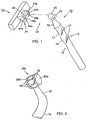
- FIG. 1 illustrated is an exploded assembly view of a three axis safety razor, generally 10, according to an exemplary embodiment of the present disclosure.
- the razor 10 includes a handle 12, and a blade cartridge 14 pivotally connected to the handle 12.
- the handle 12 includes a gripping portion 16.
- the gripping portion 16 is illustrated as generally cylindrical, however, it is contemplated, and, in fact, preferred that the gripping portion 16 have some features to enhance its friction when held in the hand of the user.
- the shape of the gripping portion 16 may be varied from the generally right circular cylinder as illustrated, for example, to other prismatic shapes such as triangular, rectangular (including square) or hexagonal prisms, among others, and/or to optionally include some combination of lands and curves.
- the gripping portion 16 may be further provided with one or more localized depressions 17 and/or protuberances 19 to receive the fingers of a user's hand.
- the surface of the gripping portion 16 may be provided with texture and/or friction enhancements, including without limitation knurling, localized or general surface roughening, and friction-enhancing appliqués 21, including those which may raise the height of the surface to which they are applied.
- a pivot sphere 20 is secured to and/or made part of the handle 12.
- the pivot sphere may be formed by a plurality of elements 40 approximating a sphere (or part thereof).
- those elements 40 may themselves be resilient to deform from a spherical surface to permit the pivot sphere 20 to be connected with the blade cartridge 14.
- the gaps 42 between elements 40 are substantially parallel with one another and circumferential with the sphere 20. This need not be the case, however.
- the gaps may be formed around poles of the sphere that are not substantially aligned with the stops 32a, 32b, as illustrated.
- the gaps 42 may be formed to meet at or near the attachment with arm 22.
- pivot sphere 20 is mounted to the handle 12 at the end of an arm 22.
- Arm 22 preferably achieves a reduction in diameter from the gripping portion 16 of the handle 12, to reduce and/or avoid obstructing the pivoting of the blade cartridge 14 about the pivot sphere 20.
- arm 22 is frusto-conical in shape, with a smaller diameter end adjacent to and connected with the pivot sphere.
- the arm 22 may be offset such that its longitudinal axis diverges from a longitudinal axis of the handle 12 generally, or gripping portion 16 specifically, in order to further distance the blade cartridge 14 from the handle 12.
- the arm 22 supporting the pivot sphere 20 may be mounted along the length of the handle 12, rather than at or near an end.
- One manner of mounting the arm 22 may be substantially perpendicular to the axis of the handle 12, approximating a "T"-shape between the handle 12 and the arm 22.
- Other configurations, e.g., "C”, “J”, “L”, “Y”-shaped combinations of handle 12 and arm 22, are clearly conceivable within the scope of the instant disclosure.
- Blade cartridge 14 includes a clevis 24 for pivotably securing the blade cartridge 14 to the pivot sphere 20.
- the clevis 24 includes two opposed legs 24a, 24b. Each leg 24a, 24b has a hole 26a, 26b, respectively.
- holes 26a, 26b are through holes which traverse their respective legs 24a, 24b, however, they need not perforate the legs 24a, 24b entirely.
- Holes 26a, 26b are sized and spaced such that the clevis 24 can be installed over the pivot sphere 20, and be retained there in connection with the handle 12.
- the tolerances of fit between the clevis 24, specifically holes 26a, 26b, and pivot sphere 20, are readily adjustable by those having skill in the art without departing from the scope of the present disclosure. In a preferred embodiment, the tolerances are set to achieve a fit between clevis 24 and sphere 20 such that the cartridge 14 holds its orientation with respect to the handle 12 at rest, yet pivots freely under any applied pressure.
- the clevis 24 is optionally provided with a recess 30, between legs 24a, 24b and below holes 26a, 26b.
- the recess may be configured as a spherical section, or alternately may resemble a portion of a torus.
- the radius of the recess 30 when configured as a spherical section, or the outer radius of the torus section where configured as such, is preferably no smaller than the diameter of the pivot sphere 20. The recess should not interfere with the pivoting of the blade cartridge on the pivot sphere.
- a close fit between the pivot sphere 20 and the recess 30 may enhance the ability of the cartridge 14 to hold its position, and can also inhibit the ingress of water or shaving detritus (e.g., foam, cut hair, etc.) that might inhibit the ability of the cartridge to change position under pressure.
- water or shaving detritus e.g., foam, cut hair, etc.
- the maximum diameter of the pivot sphere 20 is greater than the distance between the legs 24a, 24b, and their included holes 26a, 26b, or more specifically, the nearest facing surfaces of legs 24a, 24b and/or holes 26a, 26b.
- either the pivot sphere 20, or one or both of legs 24a, 24b, or any of them may be constructed of a resilient material which yields to the degree necessary to mate the cartridge 14 to the handle 12, yet return to their previous respective states once assembled.
- the clevis 24 may be provided with one or more relief portions 28a, 28b as illustrated.
- Relief portions in this exemplary embodiment are generally spherical sections, and preferably have a radius at least as great as that of the pivot sphere 20.
- Relief portions 28a, 28b guide and ease the interface between the pivot sphere 20 and the clevis 24 on their assembly. In connection with this, making the interface between the pivot sphere 20 and the clevis 24 easy and reliable makes it possible to allow the user to exchange and replace the blade cartridge 14 at that interface in the ordinary course of use. This eliminates the need for an additional point of separation to achieve a blade change, thereby simplifying the construction of the blade cartridge 14. However, this does not exclude an additional point of separation, pivoting and/or articulation in connection with blade cartridge 14 described in the present disclosure.
- the clevis 24 described herein is advantageously formed of an injection molded plastic and/or metal, for economic benefits in cost of material and manufacture. Alternately, the clevis 24 can be formed and injection molded integrally with the frame of the blade cartridge 14, which is completed by the addition of the blades themselves, among other accessories as desired.
- a razor 10 has a blade cartridge 14 that can freely move around three axes of the handle 12.
- This can be accomplished by altering the shape of the pivot sphere 20, for example to provide a stop 32.
- the stop 32 is sized and positioned to obstruct the clevis 24, and thereby limit its range of motion about the pivot sphere 20.
- the stop 32 is formed integrally with the remainder of the pivot sphere 20, as a molded part thereof.
- the stop 32 may be a separate structure, secured either permanently or removably to the pivot sphere 20, for example, without limitation, by adhesive or fastener.
- One or more such stops 32 may be provided, which individually or in combination can permit nearly any desired range of motion in the blade cartridge 14 about the handle 12.
- the stop 32 is illustrated in Fig. 1 as a simple circular cylindrical projection. However, the size, shape and height of the stop 32, or several of them, may be selected as desired in consideration of the shape of the clevis 24 and specifically its legs 24a, 24b.
- the stop 32 may be shaped to obstruct movement in certain orientations, but not in others. As an example only, once connected in the orientation illustrated in Fig. 1 , the stop 32 largely inhibits the lateral rotation of the blade cartridge 14. On the other hand, the blade cartridge 14 is free to rotate about its transverse axis, to 'lift its head' in a manner of speaking.
- the blade cartridge now has additional freedom of lateral rotation, not possible in the prior orientation because of the interaction of the legs 24a, 24b with the stop 32.
- This discussion is offered merely as an example of the possible range of motion that could be obtained by the configuration of the stop 32, and further alteration will be apparent to those of ordinary skill in the art in light of the instant disclosure.
- stops 32a, 32b are substantially diametrically opposed to one another on the pivot sphere 20.
- Stops 32a, 32b are, in this embodiment formed by deforming a spherical section into a plane, with the excess material rising above the surface of the sphere 20 to restrict the movement of the blade cartridge 14.
- the embodiment of Fig. 2 includes the planes formed by this method of creating stops 32a, 32b being angled with respect to one another. The planes are closer together at the attachment of the sphere 20 with the arm 22. They may, in other embodiments, be angled differently, or parallel with each other.
Landscapes
- Life Sciences & Earth Sciences (AREA)
- Forests & Forestry (AREA)
- Engineering & Computer Science (AREA)
- Mechanical Engineering (AREA)
- Food-Manufacturing Devices (AREA)
- Packaging Of Annular Or Rod-Shaped Articles, Wearing Apparel, Cassettes, Or The Like (AREA)
Claims (16)
- Accessoire de toilette personnel (10), comprenant:un manche (12) comprenant une partie de préhension (16) et une partie de fixation (20) utilisable pour supporter de façon rotative une cartouche (14) pour un mouvement rotatif autour d'au moins deux axes, dans lequel la partie de fixation (20) comprend un bras de fixation (22) par lequel la partie de fixation (20) est montée sur le manche (12); etune cartouche (14) comprenant une fourche à rotule (24) présentant des première et seconde branches opposées (24a, 24b), espacées l'une de l'autre, chacune des première et seconde branches opposées (24a, 24b) comportant un évidement respectif (26a, 26b) dans un côté faisant face à la branche opposée, les évidements respectifs (26a, 26b) étant dimensionnés, configurés et positionnés de telle sorte que la partie de fixation (20) soit reçue simultanément dans les deux évidements (26a, 26b), la cartouche (14) étant montée de façon pivotante sur la partie de fixation (20) avec une liberté de mouvement autour d'au moins deux axes,caractérisé en ce que la partie de fixation (20) comprend en outre au moins un arrêt (32) qui s'étend au-dessus de sa surface afin d'empêcher partiellement la rotation de la cartouche (14) lorsque la cartouche (14) est montée sur la partie de fixation (20).
- Accessoire de toilette personnel (10) selon la revendication 1, dans lequel la cartouche (14) comporte en outre un évidement central (30) entre les première et seconde branches (24a, 24b) qui reçoit et couvre sensiblement une extrémité de la partie de fixation (20).
- Accessoire de toilette personnel (10) selon la revendication 1, dans lequel la partie de fixation (20) comprend une sphère ou une partie de celle-ci présentant un premier rayon.
- Accessoire de toilette personnel (10) selon la revendication 3, dans lequel la sphère ou la partie de celle-ci comprend une pluralité d'éléments s'approchant de la surface de la sphère.
- Accessoire de toilette personnel (10) selon la revendication 4, dans lequel au moins un de la pluralité d'éléments s'approchant de la surface de la sphère est élastique de manière à faciliter la fixation entre la sphère ou la partie de celle-ci et la cartouche (14).
- Accessoire de toilette personnel (10) selon la revendication 3, dans lequel la cartouche (14) comporte en outre un évidement central (30) entre les première et seconde branches (24a, 24b) qui reçoit et couvre sensiblement une extrémité de la partie de fixation (20), l'évidement central (30) présentant soit une section sphérique soit une section toroïdale, ladite section sphérique ou ladite section toroïdale étant définie par un rayon sensiblement égal ou supérieur au premier rayon.
- Accessoire de toilette personnel (10) selon la revendication 1, dans lequel les évidements (26a, 26b) dans chacune des première et seconde branches (24a, 24b) sont soit des évidements cylindriques, soit des évidements sphériques.
- Accessoire de toilette personnel (10) selon la revendication 1, dans lequel au moins un des évidements (26a, 26b) dans chacune des première et seconde branches (24a, 24b) est une ouverture traversante qui perfore le côté de sa première ou seconde branche respective qui tourne le dos à la branche opposée.
- Accessoire de toilette personnel (10) selon la revendication 1, dans lequel au moins une des première et seconde branches (24a, 24b) comporte une partie de dépouille inclinée en direction de la branche opposée desdites première et seconde branches (24a, 24b), ladite partie de dépouille ayant pour but de faciliter l'insertion de la partie de fixation (20) entre les première et seconde branches (24a, 24b).
- Accessoire de toilette personnel (10) selon la revendication 9, dans lequel la partie de dépouille présente une surface de section sphérique.
- Accessoire de toilette personnel (10) selon la revendication 10, dans lequel la partie de fixation (20) comprend une sphère ou une partie de celle-ci qui est définie par un premier rayon, et la surface de section sphérique présente un second rayon sensiblement égal ou supérieur à celui du premier rayon.
- Accessoire de toilette personnel (10) selon la revendication 1, dans lequel au moins une des première et seconde branches (24a, 24b) comprend un matériau élastique, ladite branche pouvant être défléchie sous la pression de la partie de fixation (20) lors de l'insertion de la partie de fixation (20) entre les première et seconde branches (24a, 24b), et accepter de ce fait la partie de fixation (20) entre les première et seconde branches (24a, 24b).
- Accessoire de toilette personnel selon la revendication 1, dans lequel ledit au moins un arrêt (32) comprend deux arrêts symétriques et diamétralement opposés.
- Accessoire de toilette personnel (10) selon la revendication 1, dans lequel la cartouche (14) est montée sur la partie de fixation (20) servant à maintenir l'orientation de la cartouche (14) par rapport au manche (12) au repos, tout en pouvant pivoter librement en cas d'application d'une pression.
- Accessoire de toilette personnel (10) selon la revendication 1 dans lequel le bras de fixation (22) s'étend sous un certain angle par rapport à l'axe du manche (12).
- Accessoire de toilette personnel (10) selon la revendication 1, dans lequel le bras de fixation (22) est de forme tronconique, et est attaché au manche (12) par une partie de relativement plus grand diamètre du bras de fixation.
Priority Applications (1)
| Application Number | Priority Date | Filing Date | Title |
|---|---|---|---|
| EP20140002018 EP2783817A1 (fr) | 2010-08-11 | 2011-08-11 | Rasoir à capacité multi-positions à trois axes |
Applications Claiming Priority (3)
| Application Number | Priority Date | Filing Date | Title |
|---|---|---|---|
| US37266210P | 2010-08-11 | 2010-08-11 | |
| US13/030,752 US8720072B2 (en) | 2010-08-11 | 2011-02-18 | Razor with three-axis multi-position capability |
| PCT/US2011/047330 WO2012021666A1 (fr) | 2010-08-11 | 2011-08-11 | Rasoir à positionnement multiple sur trois axes |
Related Child Applications (2)
| Application Number | Title | Priority Date | Filing Date |
|---|---|---|---|
| EP20140002018 Division-Into EP2783817A1 (fr) | 2010-08-11 | 2011-08-11 | Rasoir à capacité multi-positions à trois axes |
| EP20140002018 Division EP2783817A1 (fr) | 2010-08-11 | 2011-08-11 | Rasoir à capacité multi-positions à trois axes |
Publications (3)
| Publication Number | Publication Date |
|---|---|
| EP2603359A1 EP2603359A1 (fr) | 2013-06-19 |
| EP2603359A4 EP2603359A4 (fr) | 2014-01-01 |
| EP2603359B1 true EP2603359B1 (fr) | 2016-11-23 |
Family
ID=44141311
Family Applications (2)
| Application Number | Title | Priority Date | Filing Date |
|---|---|---|---|
| EP20140002018 Withdrawn EP2783817A1 (fr) | 2010-08-11 | 2011-08-11 | Rasoir à capacité multi-positions à trois axes |
| EP11817015.8A Not-in-force EP2603359B1 (fr) | 2010-08-11 | 2011-08-11 | Rasoir à positionnement multiple sur trois axes |
Family Applications Before (1)
| Application Number | Title | Priority Date | Filing Date |
|---|---|---|---|
| EP20140002018 Withdrawn EP2783817A1 (fr) | 2010-08-11 | 2011-08-11 | Rasoir à capacité multi-positions à trois axes |
Country Status (4)
| Country | Link |
|---|---|
| US (5) | US8720072B2 (fr) |
| EP (2) | EP2783817A1 (fr) |
| CN (1) | CN103189170B (fr) |
| WO (1) | WO2012021666A1 (fr) |
Families Citing this family (47)
| Publication number | Priority date | Publication date | Assignee | Title |
|---|---|---|---|---|
| US8455648B2 (en) * | 2008-04-24 | 2013-06-04 | Abbott Gmbh & Co. Kg | 1-(7-(hexahydropyrrolo [3,4-c] pyrrol-2 (1H)-yl) quinolin-4-yl) -3- (pyrazin-2-yl) urea derivatives and related compounds as glycogen synthase kinase 3 (GSK-3) |
| US20100313426A1 (en) * | 2009-06-12 | 2010-12-16 | Terence Gordon Royle | Safety razor with pivot and rotation |
| US8474144B2 (en) * | 2009-08-12 | 2013-07-02 | The Gillette Company | Safety razor with rotational movement and locking button |
| US8720072B2 (en) | 2010-08-11 | 2014-05-13 | Thomas J. Bucco | Razor with three-axis multi-position capability |
| US8745882B2 (en) | 2010-09-29 | 2014-06-10 | The Gillette Company | Flexible and separable portion of a razor handle |
| US8745883B2 (en) | 2010-09-29 | 2014-06-10 | The Gillette Company | Razor handle with a rotatable portion |
| PL2508309T3 (pl) | 2011-04-05 | 2017-02-28 | The Gillette Company | Uchwyt maszynki do golenia z obrotową częścią |
| US20150089822A1 (en) * | 2012-03-22 | 2015-04-02 | Sheldon Reid | Personal Grooming Device |
| US9545731B2 (en) * | 2012-03-22 | 2017-01-17 | Sheldon Reid | Personal grooming device |
| US8938885B2 (en) | 2012-05-01 | 2015-01-27 | The Gillette Company | Razor handle with a rotatable portion |
| CN104936750B (zh) * | 2012-12-21 | 2018-10-16 | 比克-维尔莱克 | 剃须刀 |
| BR112015013766B1 (pt) * | 2012-12-21 | 2021-10-13 | Bic-Violex Sa | Aparelho de barbear e conjunto de cabeça e cabo para um aparelho de barbear |
| US10478982B2 (en) * | 2013-05-08 | 2019-11-19 | Lee Innovations, LLC | Compliant or rollable cutting surface and cutting device |
| DE102013213881A1 (de) * | 2013-07-16 | 2015-01-22 | Beiersdorf Ag | Rasierer mit freier Beweglichkeit des Rasierkopfes |
| US9604376B2 (en) * | 2013-12-04 | 2017-03-28 | Skyworld Innovations, LLC | Personal grooming assistant |
| US9718200B2 (en) | 2014-01-31 | 2017-08-01 | Dryfhout Enterprises, Llc | Safety razor with comb and integrated blade and associated methods |
| US12280512B2 (en) | 2014-01-31 | 2025-04-22 | Bakblade Limited | Safety razor with comb and blade |
| EP2902156B1 (fr) * | 2014-01-31 | 2017-11-22 | Feintechnik GmbH Eisfeld | Rasoir doté d'une poignée et d'une unité de coupe rotative |
| US10406704B2 (en) | 2014-10-06 | 2019-09-10 | OneBlade, Inc. | Razor apparatus and shaving system |
| USD765912S1 (en) | 2016-03-23 | 2016-09-06 | Phan Thi Minh Vinh | Razor handle |
| US10652956B2 (en) | 2016-06-22 | 2020-05-12 | The Gillette Company Llc | Personal consumer product with thermal control circuitry and methods thereof |
| WO2018007845A1 (fr) * | 2016-07-08 | 2018-01-11 | Bic Violex S.A. | Rasoirs reconfigurables à tête articulée |
| US10538005B2 (en) | 2016-10-25 | 2020-01-21 | OneBlade, Inc. | Single-blade razor apparatus |
| US11998282B2 (en) | 2016-12-16 | 2024-06-04 | Intuitive Surgical Operations, Inc. | Systems and methods for teleoperated control of an imaging instrument |
| EP3351358B1 (fr) | 2017-01-20 | 2019-11-20 | The Gillette Company LLC | Élément chauffant pour un rasoir |
| USD802842S1 (en) | 2017-03-15 | 2017-11-14 | Vu Phan Quang Ngo | Safety razor handle |
| USD815776S1 (en) | 2017-10-08 | 2018-04-17 | Vu Phan Quang Ngo | Safety razor |
| WO2019190962A1 (fr) | 2018-03-30 | 2019-10-03 | The Gillette Company Llc | Manche de rasoir ayant une partie pivotante |
| USD874061S1 (en) | 2018-03-30 | 2020-01-28 | The Gillette Company Llc | Shaving razor cartridge |
| US12240135B2 (en) | 2018-03-30 | 2025-03-04 | The Gillette Company Llc | Razor handle with a pivoting portion |
| JP7090727B2 (ja) * | 2018-03-30 | 2022-06-24 | ザ ジレット カンパニー リミテッド ライアビリティ カンパニー | 枢動部分を有するかみそりハンドル |
| CN111819047B (zh) | 2018-03-30 | 2022-11-08 | 吉列有限责任公司 | 具有可移动构件的剃刀柄部 |
| JP2021516102A (ja) | 2018-03-30 | 2021-07-01 | ザ ジレット カンパニー リミテッド ライアビリティ カンパニーThe Gillette Company Llc | 枢動部分を有するかみそりハンドル |
| BR112020020117A2 (pt) | 2018-03-30 | 2021-01-26 | The Gillette Company Llc | cartucho para aparelho de barbear ou depilar |
| US11607820B2 (en) | 2018-03-30 | 2023-03-21 | The Gillette Company Llc | Razor handle with movable members |
| WO2019191231A1 (fr) | 2018-03-30 | 2019-10-03 | The Gillette Company Llc | Manche de rasoir comprenant une partie pivotante |
| BR112020020132A2 (pt) | 2018-03-30 | 2021-01-05 | The Gillette Company Llc | Empunhadura de aparelho de barbear ou depilar com membros móveis |
| WO2019191345A1 (fr) | 2018-03-30 | 2019-10-03 | The Gillette Company Llc | Poignée de rasoir comprenant une partie rotative |
| JP2021516136A (ja) | 2018-03-30 | 2021-07-01 | ザ ジレット カンパニー リミテッド ライアビリティ カンパニーThe Gillette Company Llc | 可動部材を有するかみそりハンドル |
| EP3546156B1 (fr) | 2018-03-30 | 2021-03-10 | The Gillette Company LLC | Manche de rasoir comportant une partie pivotante |
| WO2019190911A1 (fr) | 2018-03-30 | 2019-10-03 | The Gillette Company Llc | Système de rasoir |
| CN111819045A (zh) | 2018-03-30 | 2020-10-23 | 吉列有限责任公司 | 具有枢转部分的剃刀柄部 |
| US11186002B2 (en) * | 2018-07-23 | 2021-11-30 | Carol Starr | Duette versatile multi-headed shaver |
| EP3616861B1 (fr) | 2018-08-31 | 2021-08-18 | BIC-Violex S.A. | Ensemble rasoir |
| EP4015169B1 (fr) | 2018-09-14 | 2024-10-30 | BIC Violex Single Member S.A. | Ensemble rasoir |
| US10882200B1 (en) | 2018-12-12 | 2021-01-05 | Mark Shabel | Razor with rotatable blade head |
| EP3666479B1 (fr) * | 2018-12-14 | 2024-01-24 | BIC Violex Single Member S.A. | Mécanisme de fixation d'un ensemble de lame et ensemble de rasoir modulaire |
Family Cites Families (181)
| Publication number | Priority date | Publication date | Assignee | Title |
|---|---|---|---|---|
| US650337A (en) | 1898-07-30 | 1900-05-22 | Libby Harlow & Company | Safety-razor. |
| US831259A (en) | 1906-02-05 | 1906-09-18 | Charles F Bingler | Safety-razor. |
| US1015575A (en) | 1911-04-08 | 1912-01-23 | Felix Meyer | Razor. |
| US1450604A (en) * | 1919-02-20 | 1923-04-03 | Mossberg Pressed Steel Corp | Razor |
| US1552234A (en) | 1919-12-23 | 1925-09-01 | Alvah C Roebuck | Safety razor |
| US1470757A (en) * | 1920-11-03 | 1923-10-16 | Luxe Brush Company De | Safety razor |
| US1455750A (en) * | 1921-12-13 | 1923-05-15 | Hartman Harry Buxton | Safety razor |
| US1452002A (en) * | 1922-02-21 | 1923-04-17 | Reiter Gustaf Adolf | Safety razor |
| US1455726A (en) * | 1922-05-03 | 1923-05-15 | Hartman Harry Buxton | Safety razor |
| US1455751A (en) | 1922-07-06 | 1923-05-15 | Hartman Harry Buxton | Safety razor |
| US1639441A (en) | 1926-01-28 | 1927-08-16 | Spahr Otto | Safety razor |
| US1693532A (en) | 1927-12-10 | 1928-11-27 | Albert Vanburen Vines | Safety razor |
| US1827148A (en) * | 1929-06-17 | 1931-10-13 | Hartman Harry Buxton | Safety razor |
| GB426651A (en) | 1932-10-08 | 1935-04-08 | Erich Kirmes | Improvements in or relating to safety razors |
| GB397346A (en) | 1932-11-21 | 1933-08-24 | David Smith Mills | Improvements in and relating to safety razors |
| US2029532A (en) * | 1933-07-14 | 1936-02-04 | Arthur A Karcher | Adjustable lamp support |
| US2023564A (en) * | 1934-09-20 | 1935-12-10 | Thomas E Winn | Safety razor and blade therefor |
| US2019077A (en) * | 1935-01-07 | 1935-10-29 | Haulton Thomas | Razor |
| FR784362A (fr) | 1935-01-16 | 1935-07-22 | Rasoir de sûreté | |
| FR788033A (fr) | 1935-03-29 | 1935-10-02 | Nouveau système de rasoir de sûreté | |
| US2119792A (en) * | 1935-06-01 | 1938-06-07 | Theodore W Foster & Bro Co | Razor with adjustable handle |
| US2083172A (en) | 1935-07-23 | 1937-06-08 | Roland L Smith | Razor handle |
| US2194815A (en) | 1936-07-08 | 1940-03-26 | Gillette Safety Razor Co | Shaving implement |
| US2165046A (en) * | 1936-08-12 | 1939-07-04 | Greenstein George | Shaving instrument and blade therefor |
| GB483608A (en) | 1937-05-03 | 1938-04-22 | Sir Hari Singh Gour | Improvements in safety razors |
| US2211255A (en) | 1938-05-20 | 1940-08-13 | Claassen Richard | Safety razor |
| US2397555A (en) * | 1944-09-13 | 1946-04-02 | James C Friel | Razor |
| US2502585A (en) * | 1946-04-19 | 1950-04-04 | Oberheim Jacob | Safety razor |
| US2694538A (en) | 1948-06-18 | 1954-11-16 | Clanton | Supporting means for rod-shaped bodies |
| US2510951A (en) * | 1948-08-06 | 1950-06-13 | Edward F Bleeker | Magazine safety razor |
| US2748468A (en) * | 1949-03-19 | 1956-06-05 | Gillette Co | Safety razor |
| US2592488A (en) * | 1949-08-05 | 1952-04-08 | Gillette Safety Razor Co | Safety razor |
| US2780866A (en) * | 1951-04-09 | 1957-02-12 | Central Ind Corp | Safety razor |
| US2748470A (en) * | 1952-09-08 | 1956-06-05 | Central Ind Corp | Means for connecting a safety razor head and handle |
| US2844870A (en) | 1954-12-02 | 1958-07-29 | Rafael P Roces | Safety razor with improved handle |
| US3090642A (en) | 1958-09-28 | 1963-05-21 | Viktor Langen | Ball and socket joints |
| US3604044A (en) * | 1969-06-27 | 1971-09-14 | Ronald W Johnson | Brush with movable head |
| GB1460732A (en) | 1973-03-01 | 1977-01-06 | Gillette Co | Safety razor |
| US3950848A (en) | 1974-03-18 | 1976-04-20 | Michael Goldstein | Safety razor |
| US3950849A (en) | 1974-07-23 | 1976-04-20 | The Gillette Company | Razor with rotatably mounted shaving unit |
| US3964160A (en) | 1975-04-02 | 1976-06-22 | Garron Gordon | Safety razor with an angularly adjustable head |
| US4083103A (en) * | 1975-09-19 | 1978-04-11 | Estandian Ramon D | Adjustable safety razor |
| CH612616A5 (fr) * | 1977-01-17 | 1979-08-15 | Morris Ag | |
| CA1045365A (fr) | 1977-12-05 | 1979-01-02 | Carlo M. Capodacqua | Lame de rasoir de surete a deux fils |
| US4152828A (en) * | 1978-03-29 | 1979-05-08 | Lund Lloyd W | Razor having variable angle and tilt of its blade |
| US4332321A (en) * | 1979-12-12 | 1982-06-01 | Otto Wratschko | Shaving kit |
| US4275498A (en) | 1979-12-31 | 1981-06-30 | Warner-Lambert Company | Safety razor blade cartridge |
| US4347663A (en) | 1980-01-16 | 1982-09-07 | Ullmo Andre A | Safety razor having movable head |
| JPS596675B2 (ja) | 1980-10-20 | 1984-02-14 | 株式会社貝印刃物開発センター | 安全かみそり |
| US4339876A (en) * | 1980-11-03 | 1982-07-20 | Davis Alton A | Shaving system and method |
| US4403414A (en) | 1981-04-09 | 1983-09-13 | Warner-Lambert Company | Socket device for a pivotal razor |
| US4422237A (en) * | 1982-02-25 | 1983-12-27 | The Gillette Company | Razor handle |
| US4411065A (en) * | 1982-02-25 | 1983-10-25 | The Gillette Company | Shaving cartridge assembly |
| US4446619A (en) | 1982-06-07 | 1984-05-08 | The Gillette Company | Razor handle |
| US4492024A (en) | 1982-09-17 | 1985-01-08 | The Gillette Company | Razor blade assembly |
| US4488357A (en) | 1982-09-17 | 1984-12-18 | The Gillette Company | Safety razor |
| US4702004A (en) * | 1985-07-24 | 1987-10-27 | Haythornthwaite James Alan | Glass razor blade and handle |
| JPS6258572U (fr) | 1985-10-01 | 1987-04-11 | ||
| JPS62104770U (fr) | 1985-12-20 | 1987-07-03 | ||
| JPS6352578U (fr) | 1986-09-25 | 1988-04-08 | ||
| WO1989010245A1 (fr) | 1988-04-20 | 1989-11-02 | Koeppen Detlef | Rasoir |
| US4779332A (en) * | 1986-12-01 | 1988-10-25 | Kemal Butka | Safety razor |
| US4797998A (en) | 1986-12-08 | 1989-01-17 | Warner-Lambert Company | Lockable pivotable razor |
| US4926553A (en) * | 1987-07-17 | 1990-05-22 | Michael Miskin | Razor |
| DE3742956A1 (de) | 1987-12-18 | 1989-06-29 | Wilkinson Sword Gmbh | Schwingkopfrasierapparat |
| GB2213837B (en) | 1987-12-22 | 1992-03-11 | Philips Electronic Associated | Electronic device manufacture with deposition of material |
| JPH0252694A (ja) | 1988-08-12 | 1990-02-22 | Feather Safety Razor Co Ltd | 安全かみそり |
| FR2639280A1 (fr) | 1988-11-24 | 1990-05-25 | Izoard Patrick | Perfectionnements aux rasoirs mecaniques, notamment jetables |
| US5515246A (en) * | 1988-12-16 | 1996-05-07 | Mag Instrument, Inc. | Holder clamp assembly |
| DE3843936C1 (fr) * | 1988-12-24 | 1990-05-31 | Braun Ag, 6000 Frankfurt, De | |
| JPH0294782U (fr) | 1989-01-12 | 1990-07-27 | ||
| DE8903182U1 (de) | 1989-03-15 | 1989-05-03 | Wilkinson Sword GmbH, 5650 Solingen | Doppel-Schwingkopf-Rasierapparat |
| US5167069A (en) * | 1989-06-02 | 1992-12-01 | Quinn Kathleen H | Razor reach |
| USD322144S (en) * | 1989-06-12 | 1991-12-03 | Bressler Group, Inc. | Safety razor |
| US5013175A (en) * | 1989-10-10 | 1991-05-07 | Ford Motor Company | Windshield wiper anti-roll connector |
| EP0463992B1 (fr) | 1990-06-22 | 1994-03-16 | Kai Industries Co. Ltd. | Rasoir mécanique |
| US5070614A (en) * | 1990-10-03 | 1991-12-10 | Hardin Terrill R | Rotary positionable razor head arrangement |
| US5093991A (en) | 1990-11-05 | 1992-03-10 | Hendrickson Terrance M | Adjustable razor |
| DE4128218C1 (fr) | 1991-08-26 | 1992-08-06 | Braun Ag, 6000 Frankfurt, De | |
| DE4128220C1 (fr) | 1991-08-26 | 1992-08-06 | Braun Ag, 6000 Frankfurt, De | |
| US5409332A (en) * | 1991-10-02 | 1995-04-25 | Chabot, Jr.; Bertin R. | Universal joint |
| CZ285654B6 (cs) * | 1991-11-27 | 1999-10-13 | The Gillette Company | Holicí strojek |
| GB9208098D0 (en) | 1992-04-13 | 1992-05-27 | Gillette Co | Razor with movable cartridge |
| US5473818A (en) | 1992-11-25 | 1995-12-12 | Matsushita Electric Works, Ltd. | Reciprocatory dry shaver |
| US5860728A (en) * | 1993-02-08 | 1999-01-19 | Mag Instrument, Inc. | Holder clamp assembly |
| US5347717A (en) * | 1993-11-05 | 1994-09-20 | Ts Ai Tse Jen | Chuck assembly for a disposable razor |
| US5560106A (en) * | 1993-11-09 | 1996-10-01 | Armbruster; Joseph M. | Resilient floating head razor |
| US5526568A (en) * | 1993-12-23 | 1996-06-18 | Copelan; Herbert W. | Razor with switch for perpendicular and limited oblique angle shaving |
| KR970010368B1 (ko) | 1994-01-18 | 1997-06-25 | 삼성전자 주식회사 | 캐시라인 리프레이스장치 및 방법 |
| US5579581A (en) | 1994-10-21 | 1996-12-03 | Wahl Clipper Corporation | Clipper blade assembly |
| US5606799A (en) * | 1994-10-21 | 1997-03-04 | Wahl Clipper Corporation | Detachable pivoting clipper blades |
| US5551115A (en) | 1995-03-20 | 1996-09-03 | Newville; Duane H. | Brush head adapted for mechanical or manual engagement |
| US5535518A (en) | 1995-03-31 | 1996-07-16 | Warner-Lambert Company | Unique two-axis pivoting shaving system |
| US5771591A (en) | 1995-09-28 | 1998-06-30 | Armbruster; Joseph M. | Disposable resilient razor |
| US5787593A (en) | 1995-11-29 | 1998-08-04 | Warner-Lambert Company | Pivoting shaving system |
| US5678316A (en) | 1995-12-15 | 1997-10-21 | Warner-Lambert Company | Disposable razor |
| USD389955S (en) * | 1996-02-09 | 1998-01-27 | American Safety Razor Company | Razor handle |
| US5704127A (en) * | 1996-03-04 | 1998-01-06 | Cordio; Caroline | Concave, convex safety razors |
| CA2197932A1 (fr) * | 1996-03-29 | 1998-08-19 | Werner O. Merlo | Joint a rotule et mecanismes pour membre artificiel |
| US5784790A (en) * | 1996-04-10 | 1998-07-28 | The Gillette Company | Shaving razor and method |
| JP3362764B2 (ja) | 1997-02-24 | 2003-01-07 | 株式会社村田製作所 | 積層型チップインダクタの製造方法 |
| CA2235115A1 (fr) | 1997-06-16 | 1998-12-16 | David C. Coffin | Corps de rasoir permettant a la tete de rasage de pivoter et de tourner |
| GB9715501D0 (en) * | 1997-07-22 | 1997-10-01 | Gillette Co | Safety razors |
| US5953824A (en) * | 1997-09-23 | 1999-09-21 | Warner-Lambert Company | Razors providing pivoting and swivelling razor head support |
| CN2330471Y (zh) | 1998-05-07 | 1999-07-28 | 贾英杰 | 手捏式刮胡须刀 |
| AT2988U1 (de) | 1998-07-24 | 1999-08-25 | Payer Lux Elektroprod | Trockenrasierapparat |
| AU5421799A (en) | 1998-08-31 | 2000-03-21 | Koninklijke Philips Electronics N.V. | Wet shaver with retractile action |
| CN1200797C (zh) | 1998-09-24 | 2005-05-11 | 特莱特克国际公司 | 具有适配器单元的剃须刀及其制造方法 |
| USD445958S1 (en) * | 1998-12-22 | 2001-07-31 | Warner-Lambert Company | Razor handle |
| US6116924A (en) | 1999-05-25 | 2000-09-12 | 3Com Corporation | Electromagnetic emissions shielding structure for circuit board connector assembly |
| US8060975B2 (en) * | 2000-01-24 | 2011-11-22 | Makolle Williams | Paint roller |
| USD444267S1 (en) * | 2000-02-29 | 2001-06-26 | The Gillette Company | Razor handle |
| US6615498B1 (en) * | 2000-03-13 | 2003-09-09 | Warner-Lambert Company | Flexible member for a shaving razor |
| US6266888B1 (en) | 2000-03-15 | 2001-07-31 | Thomas E. Zowaski | Reaching razor |
| FR2810111B1 (fr) | 2000-06-09 | 2004-04-02 | Univ Haute Alsace | Dispositif pour evaluer l'etat de surface d'un materiau et procede de mise en oeuvre dudit dispositif |
| US6880253B1 (en) * | 2000-06-23 | 2005-04-19 | Bic Violex S.A. | Razor with a movable shaving head |
| BR0003430A (pt) * | 2000-07-28 | 2004-06-08 | Dana Ind S A | Conjunto para restrição de um dos movimentos da junta esférica utilizada em veìculos automotores e afins |
| US9108329B2 (en) * | 2000-11-01 | 2015-08-18 | Sharidan L. Stiles | Personal styling razor |
| US20040035003A1 (en) * | 2000-11-01 | 2004-02-26 | Stiles Sharidan Lorraine | Personal shaving razor |
| US6336241B1 (en) | 2000-11-03 | 2002-01-08 | Gary D. Wilson | Cleaning device |
| DE10149609A1 (de) * | 2001-10-09 | 2003-04-10 | Zf Lemfoerder Metallwaren Ag | Kugelgelenk |
| DE60203153T2 (de) | 2001-10-22 | 2006-01-26 | Eveready Battery Co., Inc. | Rasiergerät |
| US7124755B2 (en) * | 2001-12-21 | 2006-10-24 | Kimberly-Clark Worldwide, Inc. | Respiratory circuit support arm |
| US7266895B2 (en) | 2002-04-24 | 2007-09-11 | Eveready Battery Company, Inc. | Razor assembly |
| US6760941B2 (en) * | 2002-05-06 | 2004-07-13 | Edward S. Coleman, Jr. | Accessory attachment for magnetic retrieval tool |
| KR100563481B1 (ko) | 2002-06-17 | 2006-03-27 | 마츠시다 덴코 가부시키가이샤 | 전기면도기의 가동헤드 유지구조 |
| US20040055159A1 (en) | 2002-09-20 | 2004-03-25 | Jeff Khomari | V-shaped razor |
| US7137205B2 (en) | 2002-10-01 | 2006-11-21 | The Gillette Company | Linkage mechanism providing a virtual pivot axis for razor apparatus with pivotal head |
| AU2004215414A1 (en) * | 2003-02-25 | 2004-09-10 | Eveready Battery Company Inc. | Shaving implement |
| US20040177519A1 (en) | 2003-03-14 | 2004-09-16 | Louis D. Tomassetti | Flexible razor and dispenser with pivoting head |
| US7044542B2 (en) * | 2003-06-02 | 2006-05-16 | Armond Muscat | Bicycle seat |
| AU2004252151B2 (en) * | 2003-06-25 | 2008-02-21 | Edgewell Personal Care Brands, Llc | Razor having a multi-position shaving head |
| GB2406537B (en) | 2003-07-21 | 2006-09-06 | Gillette Co | Safety razors |
| ATE499860T1 (de) * | 2003-11-18 | 2011-03-15 | Trisa Holding Ag | Zahnbürstenkörper |
| JP3972903B2 (ja) | 2003-12-26 | 2007-09-05 | 松下電工株式会社 | 電気かみそり |
| JP4337634B2 (ja) | 2004-05-27 | 2009-09-30 | パナソニック電工株式会社 | 往復直線運動を行う被駆動部材を備えたヘッド部が本体部に対して揺動可能な電動器具 |
| DE202004014032U1 (de) | 2004-09-09 | 2004-12-23 | Hronec, Tomas | Rasierapparat für den Rücken |
| US7475483B2 (en) | 2005-07-11 | 2009-01-13 | Eveready Battery Company, Inc. | Shaving implement |
| JP2007151925A (ja) | 2005-12-07 | 2007-06-21 | Izumi Products Co | ロータリー式電気かみそり |
| ATE509546T1 (de) * | 2006-03-24 | 2011-06-15 | Trisa Holding Ag | Zahnbürste mit facettengriff |
| US7341017B2 (en) * | 2006-06-07 | 2008-03-11 | J&J Machine & Tool, Inc. | Hydraulically locked boat accessory mounting device |
| DE202006011254U1 (de) | 2006-07-19 | 2006-12-07 | Otten, Jens | Nassrasiersystem |
| US20080034591A1 (en) | 2006-08-08 | 2008-02-14 | Kam Fai Fung | Shaver with swivel head |
| US20080086899A1 (en) * | 2006-10-12 | 2008-04-17 | Gallagher Richard N | Razor head and method for making the same |
| USD568000S1 (en) * | 2006-12-22 | 2008-04-29 | American Safety Razor | Razor handle |
| USD566897S1 (en) * | 2006-12-27 | 2008-04-15 | Dorco Co., Ltd. | Razor |
| DE102007005853A1 (de) | 2007-02-01 | 2008-08-07 | Braun Gmbh | Haarentfernungsgerät |
| CN201089169Y (zh) | 2007-04-16 | 2008-07-23 | 李丐腾 | 电动剃须刀刀头结构 |
| CN100577372C (zh) | 2007-04-24 | 2010-01-06 | 杨新胜 | 剃须刀头 |
| CN201077087Y (zh) * | 2007-07-12 | 2008-06-25 | 林镇榕 | 滑块式剃须刀架 |
| US8448248B2 (en) * | 2007-07-23 | 2013-05-21 | Samsung Electronics Co., Ltd. | Apparatus and method for repairing computer system infected by malware |
| CN101362341A (zh) | 2007-08-06 | 2009-02-11 | 曹伟明 | 旋转式剃须刀的内切刀浮动传动装置 |
| JP2009045164A (ja) | 2007-08-17 | 2009-03-05 | Nikken Kamisori Kk | 背剃りカミソリ |
| GB2458316A (en) | 2008-03-14 | 2009-09-16 | Giles Coutts | Manual shaving razor with head rotatably mounted on handle |
| FR2929496B1 (fr) | 2008-04-08 | 2011-01-28 | Oreal | Applicateur vibrant a orientation selective des vibrations |
| US20090255124A1 (en) * | 2008-04-11 | 2009-10-15 | Hassam Hasbani | Cartridge for a Shaving Razor |
| AU2009260609A1 (en) | 2008-06-19 | 2009-12-23 | The Gillette Company | Safety razor having pivotable blade unit |
| US20100005669A1 (en) * | 2008-07-14 | 2010-01-14 | Florina Winter | Razor Handle |
| JP5318951B2 (ja) | 2008-07-15 | 2013-10-16 | ブラウン ゲーエムベーハー | ハイブリッド除毛装置 |
| US8205344B2 (en) * | 2008-08-20 | 2012-06-26 | The Gillette Company | Safety razor having pivotable blade unit |
| GB2463035A (en) | 2008-08-29 | 2010-03-03 | James Bartholomew Philpotts | Manual shaving razor with damping elastic elements |
| US8671577B2 (en) * | 2008-12-03 | 2014-03-18 | Thomas A. Brown | Razor with independent suspension |
| US20100313426A1 (en) | 2009-06-12 | 2010-12-16 | Terence Gordon Royle | Safety razor with pivot and rotation |
| JP5473462B2 (ja) | 2009-08-06 | 2014-04-16 | 株式会社泉精器製作所 | ロータリー式電気かみそり |
| US8474144B2 (en) | 2009-08-12 | 2013-07-02 | The Gillette Company | Safety razor with rotational movement and locking button |
| US9527219B2 (en) | 2009-09-25 | 2016-12-27 | Panasonic Intellectual Property Management Co., Ltd. | Electric shaver |
| WO2011094887A1 (fr) | 2010-02-03 | 2011-08-11 | Fernando Fernandez Telleria | Rasoir manuel avec cartouche rotative porteuse d'une pluralité d'unités de coupe à double arête |
| EP2404715B1 (fr) | 2010-07-10 | 2012-11-28 | Braun GmbH | Rasoir électrique avec dispositif de coupe remplaçable |
| US8720072B2 (en) * | 2010-08-11 | 2014-05-13 | Thomas J. Bucco | Razor with three-axis multi-position capability |
| US8745883B2 (en) | 2010-09-29 | 2014-06-10 | The Gillette Company | Razor handle with a rotatable portion |
| US8745882B2 (en) | 2010-09-29 | 2014-06-10 | The Gillette Company | Flexible and separable portion of a razor handle |
| US20140109735A1 (en) * | 2012-10-19 | 2014-04-24 | Ian Raymond Shepperson | Shaving razors |
| DE102013213881A1 (de) * | 2013-07-16 | 2015-01-22 | Beiersdorf Ag | Rasierer mit freier Beweglichkeit des Rasierkopfes |
| US10406704B2 (en) * | 2014-10-06 | 2019-09-10 | OneBlade, Inc. | Razor apparatus and shaving system |
| US20160121495A1 (en) * | 2014-10-30 | 2016-05-05 | The Gillette Company | Shaving razor system including at least one magnetic element |
| US20160263757A1 (en) * | 2015-03-13 | 2016-09-15 | Terra Vandervelde | Razor Assembly |
| WO2016174498A1 (fr) | 2015-04-27 | 2016-11-03 | Synaptive Medical (Barbados) Inc. | Électroaimant adaptatif pour imagerie par résonance magnétique à haute performance |
| WO2018007845A1 (fr) * | 2016-07-08 | 2018-01-11 | Bic Violex S.A. | Rasoirs reconfigurables à tête articulée |
| KR101887119B1 (ko) * | 2017-11-21 | 2018-08-09 | 주식회사 도루코 | 면도기 조립체 |
| CN109807949B (zh) * | 2017-11-21 | 2021-05-25 | 株式会社多乐可 | 剃须刀组装体 |
| KR101894213B1 (ko) * | 2017-11-21 | 2018-09-04 | 주식회사 도루코 | 면도기 조립체 |
-
2011
- 2011-02-18 US US13/030,752 patent/US8720072B2/en active Active
- 2011-08-11 EP EP20140002018 patent/EP2783817A1/fr not_active Withdrawn
- 2011-08-11 EP EP11817015.8A patent/EP2603359B1/fr not_active Not-in-force
- 2011-08-11 CN CN201180049197.2A patent/CN103189170B/zh active Active
- 2011-08-11 WO PCT/US2011/047330 patent/WO2012021666A1/fr not_active Ceased
-
2014
- 2014-05-01 US US14/266,913 patent/US9889572B2/en active Active
-
2017
- 2017-12-20 US US15/849,118 patent/US11235486B2/en active Active
-
2022
- 2022-01-04 US US17/646,975 patent/US20220203565A1/en not_active Abandoned
-
2023
- 2023-12-15 US US18/541,727 patent/US20240131738A1/en active Pending
Also Published As
| Publication number | Publication date |
|---|---|
| US20240131738A1 (en) | 2024-04-25 |
| US20150075015A2 (en) | 2015-03-19 |
| US9889572B2 (en) | 2018-02-13 |
| US20140237828A1 (en) | 2014-08-28 |
| US20220203565A1 (en) | 2022-06-30 |
| US11235486B2 (en) | 2022-02-01 |
| US8720072B2 (en) | 2014-05-13 |
| EP2603359A4 (fr) | 2014-01-01 |
| CN103189170B (zh) | 2017-03-01 |
| US20180111281A1 (en) | 2018-04-26 |
| EP2603359A1 (fr) | 2013-06-19 |
| US20110138637A1 (en) | 2011-06-16 |
| WO2012021666A1 (fr) | 2012-02-16 |
| CN103189170A (zh) | 2013-07-03 |
| EP2783817A1 (fr) | 2014-10-01 |
Similar Documents
| Publication | Publication Date | Title |
|---|---|---|
| US11235486B2 (en) | Razor with cutting blade rotatable about multiple axes | |
| EP1295687B1 (fr) | Tondeuse avec accessoire de coupe integré | |
| US9731426B2 (en) | Rotating type razor | |
| CN102458780B (zh) | 具有枢转和旋转的安全剃刀 | |
| EP3348363B1 (fr) | Système de poignée de rasoir pour contenir une cartouche pivotable autour de deux axes | |
| CN102470536B (zh) | 具有旋转运动和锁定按钮的安全剃刀 | |
| EP2621690B1 (fr) | Partie flexible et séparable d'un manche de rasoir | |
| EP3700723B1 (fr) | Appareil de rasage | |
| JP7004703B2 (ja) | 電気シェーバ | |
| EP1827775B1 (fr) | Rasoir avec charniere entre le corps et la tete du rasoir | |
| AU2005240064A1 (en) | Biasing assembly for a razor and razor using same | |
| US11420353B2 (en) | Blade assembly attachment device and razor assembly | |
| US12115691B2 (en) | Blade assembly attachment mechanism and modular razor assembly | |
| GB2458316A (en) | Manual shaving razor with head rotatably mounted on handle | |
| EP4370291B1 (fr) | Ensemble de montage | |
| JP7744671B2 (ja) | 飛散防護カバー及び刈払機 |
Legal Events
| Date | Code | Title | Description |
|---|---|---|---|
| PUAI | Public reference made under article 153(3) epc to a published international application that has entered the european phase |
Free format text: ORIGINAL CODE: 0009012 |
|
| 17P | Request for examination filed |
Effective date: 20130311 |
|
| AK | Designated contracting states |
Kind code of ref document: A1 Designated state(s): AL AT BE BG CH CY CZ DE DK EE ES FI FR GB GR HR HU IE IS IT LI LT LU LV MC MK MT NL NO PL PT RO RS SE SI SK SM TR |
|
| DAX | Request for extension of the european patent (deleted) | ||
| A4 | Supplementary search report drawn up and despatched |
Effective date: 20131129 |
|
| RIC1 | Information provided on ipc code assigned before grant |
Ipc: B26B 21/52 20060101AFI20131125BHEP |
|
| 17Q | First examination report despatched |
Effective date: 20150618 |
|
| GRAP | Despatch of communication of intention to grant a patent |
Free format text: ORIGINAL CODE: EPIDOSNIGR1 |
|
| INTG | Intention to grant announced |
Effective date: 20160506 |
|
| GRAS | Grant fee paid |
Free format text: ORIGINAL CODE: EPIDOSNIGR3 |
|
| GRAA | (expected) grant |
Free format text: ORIGINAL CODE: 0009210 |
|
| RAP1 | Party data changed (applicant data changed or rights of an application transferred) |
Owner name: SPHERE USA, LLC |
|
| RIN1 | Information on inventor provided before grant (corrected) |
Inventor name: BUCCO, THOMAS J. |
|
| AK | Designated contracting states |
Kind code of ref document: B1 Designated state(s): AL AT BE BG CH CY CZ DE DK EE ES FI FR GB GR HR HU IE IS IT LI LT LU LV MC MK MT NL NO PL PT RO RS SE SI SK SM TR |
|
| REG | Reference to a national code |
Ref country code: GB Ref legal event code: FG4D |
|
| REG | Reference to a national code |
Ref country code: CH Ref legal event code: EP |
|
| REG | Reference to a national code |
Ref country code: IE Ref legal event code: FG4D |
|
| REG | Reference to a national code |
Ref country code: AT Ref legal event code: REF Ref document number: 847448 Country of ref document: AT Kind code of ref document: T Effective date: 20161215 |
|
| REG | Reference to a national code |
Ref country code: DE Ref legal event code: R096 Ref document number: 602011032776 Country of ref document: DE |
|
| PG25 | Lapsed in a contracting state [announced via postgrant information from national office to epo] |
Ref country code: LV Free format text: LAPSE BECAUSE OF FAILURE TO SUBMIT A TRANSLATION OF THE DESCRIPTION OR TO PAY THE FEE WITHIN THE PRESCRIBED TIME-LIMIT Effective date: 20161123 |
|
| REG | Reference to a national code |
Ref country code: LT Ref legal event code: MG4D |
|
| REG | Reference to a national code |
Ref country code: NL Ref legal event code: MP Effective date: 20161123 |
|
| REG | Reference to a national code |
Ref country code: AT Ref legal event code: MK05 Ref document number: 847448 Country of ref document: AT Kind code of ref document: T Effective date: 20161123 |
|
| PG25 | Lapsed in a contracting state [announced via postgrant information from national office to epo] |
Ref country code: NL Free format text: LAPSE BECAUSE OF FAILURE TO SUBMIT A TRANSLATION OF THE DESCRIPTION OR TO PAY THE FEE WITHIN THE PRESCRIBED TIME-LIMIT Effective date: 20161123 Ref country code: NO Free format text: LAPSE BECAUSE OF FAILURE TO SUBMIT A TRANSLATION OF THE DESCRIPTION OR TO PAY THE FEE WITHIN THE PRESCRIBED TIME-LIMIT Effective date: 20170223 Ref country code: SE Free format text: LAPSE BECAUSE OF FAILURE TO SUBMIT A TRANSLATION OF THE DESCRIPTION OR TO PAY THE FEE WITHIN THE PRESCRIBED TIME-LIMIT Effective date: 20161123 Ref country code: GR Free format text: LAPSE BECAUSE OF FAILURE TO SUBMIT A TRANSLATION OF THE DESCRIPTION OR TO PAY THE FEE WITHIN THE PRESCRIBED TIME-LIMIT Effective date: 20170224 Ref country code: LT Free format text: LAPSE BECAUSE OF FAILURE TO SUBMIT A TRANSLATION OF THE DESCRIPTION OR TO PAY THE FEE WITHIN THE PRESCRIBED TIME-LIMIT Effective date: 20161123 |
|
| PG25 | Lapsed in a contracting state [announced via postgrant information from national office to epo] |
Ref country code: PT Free format text: LAPSE BECAUSE OF FAILURE TO SUBMIT A TRANSLATION OF THE DESCRIPTION OR TO PAY THE FEE WITHIN THE PRESCRIBED TIME-LIMIT Effective date: 20170323 Ref country code: PL Free format text: LAPSE BECAUSE OF FAILURE TO SUBMIT A TRANSLATION OF THE DESCRIPTION OR TO PAY THE FEE WITHIN THE PRESCRIBED TIME-LIMIT Effective date: 20161123 Ref country code: FI Free format text: LAPSE BECAUSE OF FAILURE TO SUBMIT A TRANSLATION OF THE DESCRIPTION OR TO PAY THE FEE WITHIN THE PRESCRIBED TIME-LIMIT Effective date: 20161123 Ref country code: ES Free format text: LAPSE BECAUSE OF FAILURE TO SUBMIT A TRANSLATION OF THE DESCRIPTION OR TO PAY THE FEE WITHIN THE PRESCRIBED TIME-LIMIT Effective date: 20161123 Ref country code: RS Free format text: LAPSE BECAUSE OF FAILURE TO SUBMIT A TRANSLATION OF THE DESCRIPTION OR TO PAY THE FEE WITHIN THE PRESCRIBED TIME-LIMIT Effective date: 20161123 Ref country code: AT Free format text: LAPSE BECAUSE OF FAILURE TO SUBMIT A TRANSLATION OF THE DESCRIPTION OR TO PAY THE FEE WITHIN THE PRESCRIBED TIME-LIMIT Effective date: 20161123 Ref country code: HR Free format text: LAPSE BECAUSE OF FAILURE TO SUBMIT A TRANSLATION OF THE DESCRIPTION OR TO PAY THE FEE WITHIN THE PRESCRIBED TIME-LIMIT Effective date: 20161123 |
|
| PG25 | Lapsed in a contracting state [announced via postgrant information from national office to epo] |
Ref country code: CZ Free format text: LAPSE BECAUSE OF FAILURE TO SUBMIT A TRANSLATION OF THE DESCRIPTION OR TO PAY THE FEE WITHIN THE PRESCRIBED TIME-LIMIT Effective date: 20161123 Ref country code: SK Free format text: LAPSE BECAUSE OF FAILURE TO SUBMIT A TRANSLATION OF THE DESCRIPTION OR TO PAY THE FEE WITHIN THE PRESCRIBED TIME-LIMIT Effective date: 20161123 Ref country code: DK Free format text: LAPSE BECAUSE OF FAILURE TO SUBMIT A TRANSLATION OF THE DESCRIPTION OR TO PAY THE FEE WITHIN THE PRESCRIBED TIME-LIMIT Effective date: 20161123 Ref country code: RO Free format text: LAPSE BECAUSE OF FAILURE TO SUBMIT A TRANSLATION OF THE DESCRIPTION OR TO PAY THE FEE WITHIN THE PRESCRIBED TIME-LIMIT Effective date: 20161123 Ref country code: EE Free format text: LAPSE BECAUSE OF FAILURE TO SUBMIT A TRANSLATION OF THE DESCRIPTION OR TO PAY THE FEE WITHIN THE PRESCRIBED TIME-LIMIT Effective date: 20161123 |
|
| REG | Reference to a national code |
Ref country code: DE Ref legal event code: R097 Ref document number: 602011032776 Country of ref document: DE |
|
| PG25 | Lapsed in a contracting state [announced via postgrant information from national office to epo] |
Ref country code: IT Free format text: LAPSE BECAUSE OF FAILURE TO SUBMIT A TRANSLATION OF THE DESCRIPTION OR TO PAY THE FEE WITHIN THE PRESCRIBED TIME-LIMIT Effective date: 20161123 Ref country code: BE Free format text: LAPSE BECAUSE OF FAILURE TO SUBMIT A TRANSLATION OF THE DESCRIPTION OR TO PAY THE FEE WITHIN THE PRESCRIBED TIME-LIMIT Effective date: 20161123 Ref country code: BG Free format text: LAPSE BECAUSE OF FAILURE TO SUBMIT A TRANSLATION OF THE DESCRIPTION OR TO PAY THE FEE WITHIN THE PRESCRIBED TIME-LIMIT Effective date: 20170223 Ref country code: SM Free format text: LAPSE BECAUSE OF FAILURE TO SUBMIT A TRANSLATION OF THE DESCRIPTION OR TO PAY THE FEE WITHIN THE PRESCRIBED TIME-LIMIT Effective date: 20161123 |
|
| PLBE | No opposition filed within time limit |
Free format text: ORIGINAL CODE: 0009261 |
|
| STAA | Information on the status of an ep patent application or granted ep patent |
Free format text: STATUS: NO OPPOSITION FILED WITHIN TIME LIMIT |
|
| 26N | No opposition filed |
Effective date: 20170824 |
|
| PG25 | Lapsed in a contracting state [announced via postgrant information from national office to epo] |
Ref country code: SI Free format text: LAPSE BECAUSE OF FAILURE TO SUBMIT A TRANSLATION OF THE DESCRIPTION OR TO PAY THE FEE WITHIN THE PRESCRIBED TIME-LIMIT Effective date: 20161123 |
|
| REG | Reference to a national code |
Ref country code: CH Ref legal event code: PL |
|
| PG25 | Lapsed in a contracting state [announced via postgrant information from national office to epo] |
Ref country code: MC Free format text: LAPSE BECAUSE OF FAILURE TO SUBMIT A TRANSLATION OF THE DESCRIPTION OR TO PAY THE FEE WITHIN THE PRESCRIBED TIME-LIMIT Effective date: 20161123 |
|
| PG25 | Lapsed in a contracting state [announced via postgrant information from national office to epo] |
Ref country code: LI Free format text: LAPSE BECAUSE OF NON-PAYMENT OF DUE FEES Effective date: 20170831 Ref country code: CH Free format text: LAPSE BECAUSE OF NON-PAYMENT OF DUE FEES Effective date: 20170831 |
|
| REG | Reference to a national code |
Ref country code: FR Ref legal event code: ST Effective date: 20180430 |
|
| REG | Reference to a national code |
Ref country code: IE Ref legal event code: MM4A |
|
| PG25 | Lapsed in a contracting state [announced via postgrant information from national office to epo] |
Ref country code: LU Free format text: LAPSE BECAUSE OF NON-PAYMENT OF DUE FEES Effective date: 20170811 |
|
| PG25 | Lapsed in a contracting state [announced via postgrant information from national office to epo] |
Ref country code: IE Free format text: LAPSE BECAUSE OF NON-PAYMENT OF DUE FEES Effective date: 20170811 |
|
| PG25 | Lapsed in a contracting state [announced via postgrant information from national office to epo] |
Ref country code: FR Free format text: LAPSE BECAUSE OF NON-PAYMENT OF DUE FEES Effective date: 20170831 |
|
| PG25 | Lapsed in a contracting state [announced via postgrant information from national office to epo] |
Ref country code: MT Free format text: LAPSE BECAUSE OF NON-PAYMENT OF DUE FEES Effective date: 20170811 |
|
| PGFP | Annual fee paid to national office [announced via postgrant information from national office to epo] |
Ref country code: GB Payment date: 20190226 Year of fee payment: 8 |
|
| PG25 | Lapsed in a contracting state [announced via postgrant information from national office to epo] |
Ref country code: HU Free format text: LAPSE BECAUSE OF FAILURE TO SUBMIT A TRANSLATION OF THE DESCRIPTION OR TO PAY THE FEE WITHIN THE PRESCRIBED TIME-LIMIT; INVALID AB INITIO Effective date: 20110811 |
|
| PG25 | Lapsed in a contracting state [announced via postgrant information from national office to epo] |
Ref country code: CY Free format text: LAPSE BECAUSE OF NON-PAYMENT OF DUE FEES Effective date: 20161123 |
|
| PG25 | Lapsed in a contracting state [announced via postgrant information from national office to epo] |
Ref country code: MK Free format text: LAPSE BECAUSE OF FAILURE TO SUBMIT A TRANSLATION OF THE DESCRIPTION OR TO PAY THE FEE WITHIN THE PRESCRIBED TIME-LIMIT Effective date: 20161123 |
|
| PG25 | Lapsed in a contracting state [announced via postgrant information from national office to epo] |
Ref country code: TR Free format text: LAPSE BECAUSE OF FAILURE TO SUBMIT A TRANSLATION OF THE DESCRIPTION OR TO PAY THE FEE WITHIN THE PRESCRIBED TIME-LIMIT Effective date: 20161123 |
|
| GBPC | Gb: european patent ceased through non-payment of renewal fee |
Effective date: 20190811 |
|
| PG25 | Lapsed in a contracting state [announced via postgrant information from national office to epo] |
Ref country code: AL Free format text: LAPSE BECAUSE OF FAILURE TO SUBMIT A TRANSLATION OF THE DESCRIPTION OR TO PAY THE FEE WITHIN THE PRESCRIBED TIME-LIMIT Effective date: 20161123 Ref country code: IS Free format text: LAPSE BECAUSE OF FAILURE TO SUBMIT A TRANSLATION OF THE DESCRIPTION OR TO PAY THE FEE WITHIN THE PRESCRIBED TIME-LIMIT Effective date: 20170323 |
|
| PG25 | Lapsed in a contracting state [announced via postgrant information from national office to epo] |
Ref country code: GB Free format text: LAPSE BECAUSE OF NON-PAYMENT OF DUE FEES Effective date: 20190811 |
|
| PGFP | Annual fee paid to national office [announced via postgrant information from national office to epo] |
Ref country code: DE Payment date: 20200828 Year of fee payment: 10 |
|
| REG | Reference to a national code |
Ref country code: DE Ref legal event code: R119 Ref document number: 602011032776 Country of ref document: DE |
|
| PG25 | Lapsed in a contracting state [announced via postgrant information from national office to epo] |
Ref country code: DE Free format text: LAPSE BECAUSE OF NON-PAYMENT OF DUE FEES Effective date: 20220301 |