EP2603364B1 - Système de guidage pour scie électrique - Google Patents
Système de guidage pour scie électrique Download PDFInfo
- Publication number
- EP2603364B1 EP2603364B1 EP11743943.0A EP11743943A EP2603364B1 EP 2603364 B1 EP2603364 B1 EP 2603364B1 EP 11743943 A EP11743943 A EP 11743943A EP 2603364 B1 EP2603364 B1 EP 2603364B1
- Authority
- EP
- European Patent Office
- Prior art keywords
- fence
- elongated
- fence system
- support unit
- movable arm
- Prior art date
- Legal status (The legal status is an assumption and is not a legal conclusion. Google has not performed a legal analysis and makes no representation as to the accuracy of the status listed.)
- Not-in-force
Links
- 238000005520 cutting process Methods 0.000 claims description 15
- 239000000463 material Substances 0.000 claims description 11
- 229910052751 metal Inorganic materials 0.000 claims description 3
- 239000002184 metal Substances 0.000 claims description 3
- 229910052782 aluminium Inorganic materials 0.000 claims description 2
- XAGFODPZIPBFFR-UHFFFAOYSA-N aluminium Chemical compound [Al] XAGFODPZIPBFFR-UHFFFAOYSA-N 0.000 claims description 2
- 238000001125 extrusion Methods 0.000 claims 1
- 239000011120 plywood Substances 0.000 description 4
- 230000006378 damage Effects 0.000 description 1
- 230000001419 dependent effect Effects 0.000 description 1
- 210000004905 finger nail Anatomy 0.000 description 1
Images




Classifications
-
- B—PERFORMING OPERATIONS; TRANSPORTING
- B27—WORKING OR PRESERVING WOOD OR SIMILAR MATERIAL; NAILING OR STAPLING MACHINES IN GENERAL
- B27B—SAWS FOR WOOD OR SIMILAR MATERIAL; COMPONENTS OR ACCESSORIES THEREFOR
- B27B25/00—Feeding devices for timber in saw mills or sawing machines; Feeding devices for trees
- B27B25/10—Manually-operated feeding or pressing accessories, e.g. pushers
-
- Y—GENERAL TAGGING OF NEW TECHNOLOGICAL DEVELOPMENTS; GENERAL TAGGING OF CROSS-SECTIONAL TECHNOLOGIES SPANNING OVER SEVERAL SECTIONS OF THE IPC; TECHNICAL SUBJECTS COVERED BY FORMER USPC CROSS-REFERENCE ART COLLECTIONS [XRACs] AND DIGESTS
- Y10—TECHNICAL SUBJECTS COVERED BY FORMER USPC
- Y10T—TECHNICAL SUBJECTS COVERED BY FORMER US CLASSIFICATION
- Y10T83/00—Cutting
- Y10T83/647—With means to convey work relative to tool station
- Y10T83/6572—With additional mans to engage work and orient it relative to tool station
-
- Y—GENERAL TAGGING OF NEW TECHNOLOGICAL DEVELOPMENTS; GENERAL TAGGING OF CROSS-SECTIONAL TECHNOLOGIES SPANNING OVER SEVERAL SECTIONS OF THE IPC; TECHNICAL SUBJECTS COVERED BY FORMER USPC CROSS-REFERENCE ART COLLECTIONS [XRACs] AND DIGESTS
- Y10—TECHNICAL SUBJECTS COVERED BY FORMER USPC
- Y10T—TECHNICAL SUBJECTS COVERED BY FORMER US CLASSIFICATION
- Y10T83/00—Cutting
- Y10T83/647—With means to convey work relative to tool station
- Y10T83/6656—Rectilinear movement only
- Y10T83/6657—Tool opposing pusher
-
- Y—GENERAL TAGGING OF NEW TECHNOLOGICAL DEVELOPMENTS; GENERAL TAGGING OF CROSS-SECTIONAL TECHNOLOGIES SPANNING OVER SEVERAL SECTIONS OF THE IPC; TECHNICAL SUBJECTS COVERED BY FORMER USPC CROSS-REFERENCE ART COLLECTIONS [XRACs] AND DIGESTS
- Y10—TECHNICAL SUBJECTS COVERED BY FORMER USPC
- Y10T—TECHNICAL SUBJECTS COVERED BY FORMER US CLASSIFICATION
- Y10T83/00—Cutting
- Y10T83/727—With means to guide moving work
-
- Y—GENERAL TAGGING OF NEW TECHNOLOGICAL DEVELOPMENTS; GENERAL TAGGING OF CROSS-SECTIONAL TECHNOLOGIES SPANNING OVER SEVERAL SECTIONS OF THE IPC; TECHNICAL SUBJECTS COVERED BY FORMER USPC CROSS-REFERENCE ART COLLECTIONS [XRACs] AND DIGESTS
- Y10—TECHNICAL SUBJECTS COVERED BY FORMER USPC
- Y10T—TECHNICAL SUBJECTS COVERED BY FORMER US CLASSIFICATION
- Y10T83/00—Cutting
- Y10T83/727—With means to guide moving work
- Y10T83/744—Plural guide elements
-
- Y—GENERAL TAGGING OF NEW TECHNOLOGICAL DEVELOPMENTS; GENERAL TAGGING OF CROSS-SECTIONAL TECHNOLOGIES SPANNING OVER SEVERAL SECTIONS OF THE IPC; TECHNICAL SUBJECTS COVERED BY FORMER USPC CROSS-REFERENCE ART COLLECTIONS [XRACs] AND DIGESTS
- Y10—TECHNICAL SUBJECTS COVERED BY FORMER USPC
- Y10T—TECHNICAL SUBJECTS COVERED BY FORMER US CLASSIFICATION
- Y10T83/00—Cutting
- Y10T83/748—With work immobilizer
- Y10T83/7593—Work-stop abutment
- Y10T83/7607—Normal to plane of cut
Definitions
- the present invention relates to a fence system for use on a power saw according to the preamble of claim 1.
- a fence system for use on a power saw according to the preamble of claim 1.
- Such a system is known from US2985202 A1 .
- Power table saws of the type which have a relatively flat table top and a blade that extends through a slot in the table saw typically have either a universal fence or a rip fence for guiding material to be cut, such as lumber, plywood and the like wherein the work piece is moved passed the saw blade with the fence guiding the work piece so that an accurate cut of the work piece can be accomplished.
- a safety issue is presented because of the possibility of kickback of the work piece as well as close proximity of an operator's hand to the blade.
- It is highly desirable to have a fence system which incorporates features that insure safety as well as provide convenience of use.
- a fence system for use on a power saw according to the invention is defined by the features of claim 1.
- Such fences are typically mounted on parallel rails that are attached adjacent to the front and rear faces or other structure near the table top.
- the rails enable the fence design to operate so that it can be moved to either side of the blade and locked at a desired position relative to the blade so that the work piece can be cut to a desired dimension.
- the support unit is flexible in its use and is configured to be slidably mounted on the rip fence and is configured for use in various applications.
- One of the advantages of the present invention is that an upper guard covering the saw blade does not have to be removed if the operator wishes to make a cut of relatively thin material. It also has the advantage of being positioned on either side of the saw blade without losing any of its functionality.
- the support unit is also configured to be held captive within the slot so that any upward force that may be caused by a kickback or other unexpected movement will not separate the support unit from the rip fence.
- the support unit also moves the material along the fence in a manner whereby side forces that can affect the accuracy of the cut are not applied to the work piece.
- the support unit also has a design that enables it to be mounted on a fence so that the arm can be located on either side of the fence. This design feature is consistent with and desirable with the fence being capable of being located on either side of the blade.
- FIG. 1 a portion of a table saw, indicated generally at 10, is shown and has a top surface 12 in which a recess 14 is provided and through which a blade 16 extends, with the blade having a protected blade guard 18 shown above the blade. While the drawings particularly show a table saw, it should be understood that the present invention could be used with shapers and planers as well as other types of power tools that have a fence and where material to be cut or otherwise machined is moved to an operating zone where such processing occurs.
- the fence system is shown on the table top 12 and includes a support unit, indicated generally at 22, as well as a portion of a fence, indicated generally at 24.
- the fence system is shown together with a work piece 26.
- a first preferred embodiment of the fence system 20 includes the support unit 22 and fence 24, with only a short portion of the fence 24 being illustrated.
- the fence 24 would extend from a front edge 28 to a rear edge 30, with both ends of the fence 24 having structure which preferably engages front and rear rails (not shown) as well as a handle for clamping the fence 24 in a desired position.
- the fence 24 is preferably an extruded metal, such as aluminum and is shown to have a flat bottom 32, opposite side walls 34 and 36, a top portion 38 which has an elongated slot 40 formed in the top and having downward inner extensions 42 with the slot 40 being defined by the opposed surfaces of the inner extensions 42.
- the extensions have transverse portions 44 that define a generally horizontal shoulders 46 that are connected to interior side walls 48 having a connecting bottom wall 50, with the side walls 48 and bottom wall 50 defining a cavity 52 in which a portion of the support unit is located.
- the support unit 22 is configured to ride on the elongated fence 24 and it has a hand pad, indicated generally at 54, to which a movable arm, indicated generally at 56, is pivotably attached by a pivot connection, indicated generally at 58.
- the pivot connection 58 has an exposed enlarged outer portion 60 and a reduced diameter portion 62 (see FIG. 4 ) that is preferably force fit or threaded into a corresponding opening in the hand pad 54 so as to provide a strong interconnection between the arm 56 and the hand pad 54.
- the hand pad 54 has a lower extension 66 that is attached to a bottom surface 68 of the hand pad and it has an enlarged end portion 70 which is located in the cavity 52 when the support unit 22 is install on the fence 24.
- the enlarged end portion 70 has an upper surface 72 which is configured to engage the shoulders 46 so that it prevents the support unit 22 from moving upwardly and thereby holds the support unit 22 captive within the fence 24.
- the outer dimension is slightly smaller than the distance between the inner surfaces of the side walls 48 of the fence 24.
- the outer dimension of the lower extension 66 is less than the distance between the outer surfaces of the downward inner extensions 42.
- the lower extension 66 with its enlarged end portion 70 is preferably a bolt with a hexagonal head that is threaded into a corresponding opening in the bottom surface 68 of the hand pad 54; however, other structure that is configured to engage the shoulders 46 may be used if desired.
- the bottom surface 68 of the hand pad 54 is shown to be out of contact with the top surface of the top portion 38 of the fence 24, with the upper surface 72 of the enlarged end portion 70 being in contact with the shoulder 46.
- the enlarged end portion 70 has a bottom surface 74 which should be sufficiently spaced from the bottom surface 50 to provide sufficient clearance so that the bottom surface 68 of the hand pad 54 can ride on the top portion 38 of the fence 24.
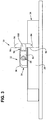
- FIGS. 1-4 preferably has a feature that is not shown in those figures, but which is shown in FIG. 5 of an alternative embodiment.
- the structure of the fence has a curved recess 80 on the inside portion of the slot 40 that is sized to enable the enlarged end portion 70 to be inserted into the cavity 52.
- the structure of the fence 24 shown in FIGS. 5-7 is otherwise substantially similar to that shown in the embodiment of FIGS. 1-4 .
- the hand pad 54 preferably has downwardly extending guide plates that are configured to have their inside surfaces positioned closely adjacent to the side walls 34 to guide the support unit when the support unit 22 is pushed along the length of the fence 24.
- These guide plates may be integrally formed with the hand pad 54 or otherwise securely attached to the hand pad 54.
- the width of the hand pad 54 extends beyond the left side wall 34 and the width of the arm 56 is relatively narrow, but has a wide bottom portion that has an end surface 86 that is configured to engage the outer surface of the left fence side wall 34 to provide additional strength and stability to the arm during use.
- the left and right surfaces 88 of the hand pad 54 are planar and the inside surface of the arm 56 is in close proximity to the left side surface 88 which provides stability against side forces.
- the top surface 90 of the hand pad 54 has a generally curved configuration that is shaped to ergonomically conform to the generally similarly curved configuration of a user's palm jwhen the user pushes the support unit 22 along the fence 24.
- the arm 56 has a stem portion 96 and a pair of transverse nose portions extending from the bottom of said stem portion, with each of the nose portions having an upper surface 96.
- the arm 56 has a thin auxiliary fence 100 that fits within a recess 102 that is hinged at its bottom end portion 104 that can be pivoted out 9 into a transverse position for cutting thin work pieces.
- the outer end has a narrow recess 106 that enables a user to easily use his or her fingernail or other tool or the like to contact the outer end and pivot it downwardly into operating position.
- the arm can be positioned so that the upper surface 96 of one of the nose pieces 94 can engage a work piece 26 so that it pulls the work piece 26 through a cutting zone.
- the arm can be placed so that the bottom surface of the nose can engage the top of the cutting zone and push it through.
- the identical reference numbers are used for this embodiment where they have a substantially similar configuration, with prime designations being given where the feature has been slightly modified.
- the embodiment shown in FIGS. 5 and 6 have a preferably corrugated rubber layer 112 that extends from the top surface 96 of the nose portions 94 completely around the bottom of the stem portion 92' and is provided to enable the nose portions to prevent slippage of the nose portion 94 if it is placed in the position shown in FIG. 2 , for example, and to also prevent the nose portions from work pieces that can be easily scratched.
- the guide plate 82' is flush with the left surface 88 of the hand pad 54 to provide stability for the arm 56' which has a thicker stem portion 92 that is substantially the same as the width of the nose portions 94.
- the auxiliary fence 100' is also configured to fit within a recess having an enlarged curved portion 108 to enable a user to reach in and engage an elongated recess 110 so that it can be pulled out into operating position. While not shown, suitable structure of the auxiliary fence 100' is provided in the opening of the arm 56' so that the auxiliary fence cannot be completely removed.
Landscapes
- Life Sciences & Earth Sciences (AREA)
- Engineering & Computer Science (AREA)
- Mechanical Engineering (AREA)
- Wood Science & Technology (AREA)
- Forests & Forestry (AREA)
- Sawing (AREA)
Claims (14)
- Système de butée destiné à être utilisé sur une scie électrique qui présente une surface supérieure plate et une zone de coupe définie par une lame de scie s'étendant à travers une ouverture dans la surface supérieure, ledit système de butée étant configuré pour guider et déplacer un matériau d'objet à travers la zone de coupe, ladite butée comprenant :une butée allongée configurée pour être fixée sur la surface supérieure plate au niveau de diverses positions par rapport à la lame de scie, ladite butée allongée comprenant au moins une portion de paroi latérale plate contre laquelle le matériau de l'objet peut être positionné et déplacé pendant que le matériau est déplacé à travers la zone de coupe ;une unité de support configurée pour resposer sur ladite butée et entrer en contact avec le matériau de l'objet afin de déplacer celui-ci à travers la zone de coupe, ladite unité comprenant un garde-main de forme ergonomique, ladite unité de support étant rapportée de façon amovible à ladite butée allongée et mobile le long de celle-ci, et un bras mobile rapporté audit garde-main de forme ergonomique qui est réalisér pour s'étendre vers le bas jusqu'à une hauteur étroitement adjacente à la surface supérieure, dans lequel ledit bras mobile est configuré pour avoir une portion de tige et une portion de nez, ladite portion de nez comprenant une première portion de nez transversale et une seconde portion de nez transversale s'étendant chacune vers l'extérieur depuis une première extrémité de ladite portion de tige, ledit bras mobile ayant une liaison de pivotement au niveau d'une seconde extrémité de ladite portion de tige, dans lequel ladite liaison de pivotement définit un axe de pivotement, caractérisé en ce que ladite première portion de nez comporte une première surface de traction et une première surface de poussée, dans lequel ladite surface de traction est configurée pour être en contact avec l'objet pendant l'opération de coupe et ladite seconde portion de nez est configurée pour ne pas être en contact avec l'objet pendant l'opération de coupe.
- Système de butée selon la revendication 1, dans lequel ladite liaison de pivotement a un diamètre relativement important pour limiter le mouvement dudit bras mobile par rapport audit garde-main de forme ergonomique en rotation autour de ladite liaison de pivotement.
- Système de butée selon la revendication 2, dans lequel ledit garde-main de forme ergonomique et ledit bras mobile ont des surfaces plates attenantes adjacentes et perpendiculaires à ladite liaison de pivotement pour assister ladite liaison de pivotement en limitant le mouvement dudit bras mobile en rotation autour de ladite liaison de pivotement.
- Système de butée selon la revendication 2, dans lequel ledit bras de forme ergonomique a une longueur qui est au moins aussi longue que la hauteur de ladite butée allongée.
- Système de butée selon la revendication 1, dans lequel ledit bras mobile a une portion de butée auxiliaire relativement fine qui est peut être rallongée depuis ladite première extrémité de ladite portion de tige.
- Système de butée selon la revendication 5, dans lequel ladite fine portion de butée auxiliaire est configurée pour s'adapter dans une ouverture dans ladite portion de tige et être rallongée de manière coulissante vers l'extérieur de celle-ci.
- Système de butée selon la revendication 5, dans lequel ladite fine portion de butée auxiliaire est configurée pour s'adapter dans un évidement dans ladite portion de tige et avoir une seconde liaison pour faire pivoter ladite fine portion de butée auxiliaire vers l'extérieur de celle-ci.
- Système de butée selon la revendication 1, dans lequel au moins une desdites deux portions de nez transversales comporte un matériau en caoutchouc ou comparable au caoutchouc sur au moins une surface de celle-ci qui peut entrer en contact avec une pièce pendant la coupe.
- Système de butée selon la revendication 1,
dans lequel ladite butée allongée a des portions de paroi latérale en regard contre lesquelles le matériau de l'objet peut être positionné et une portion supérieure plate, ladite portion supérieure plate ayant une fente allongée dans une surface supérieure de celle-ci avec une première largeur prédéterminée, une cavité centrale sous ladite fente allongée avec un épaulement supérieur généralement horizontal étant disposée sur chaque côté de la fente, ladite unité de support ayant une extension inférieure allongée avec une portion terminale élargie, ladite extension inférieure allongée ayant une dimension extérieure légèrement inférieure à la largeur de ladite fente, ladite portion terminale élargie ayant une surface supérieure configurée pour être disposée adjacente auxdits épaulements supérieurs généralement horizontaux pour limiter le mouvement vers le haut de ladite unité de support. - Système de butée selon la revendication 9, dans lequel ladite extension inférieure allongée est un boulon.
- Système de butée selon la revendication 9, dans lequel ladite unité de support a une paire d'extensions de guidage dirigées vers le bas configurées pour venir en prise avec lesdites portions de paroi latérale en regard pour faciliter le mouvement de ladite unité de support le long de ladite butée allongée.
- Système de butée selon la revendication 11, dans lequel ledit garde-main de forme ergonomique comprend une surface supérieure de ladite unité de support, ledit garde-main de forme ergonomique ayant une courbure convexe qui est configurée pour correspondre généralement à la forme d'une paume d'une main de l'opérateur.
- Système de butée selon la revendication 1, dans lequel ladite butée allongée est une extrusion constitué de métal.
- Système de butée selon la revendication 13, dans lequel ledit métal est l'aluminium.
Applications Claiming Priority (2)
| Application Number | Priority Date | Filing Date | Title |
|---|---|---|---|
| US12/854,291 US8495937B2 (en) | 2010-08-11 | 2010-08-11 | Fence system for a power saw |
| PCT/US2011/047073 WO2012021510A1 (fr) | 2010-08-11 | 2011-08-09 | Système de barrière de protection pour scie électrique |
Publications (2)
| Publication Number | Publication Date |
|---|---|
| EP2603364A1 EP2603364A1 (fr) | 2013-06-19 |
| EP2603364B1 true EP2603364B1 (fr) | 2016-06-08 |
Family
ID=44513185
Family Applications (1)
| Application Number | Title | Priority Date | Filing Date |
|---|---|---|---|
| EP11743943.0A Not-in-force EP2603364B1 (fr) | 2010-08-11 | 2011-08-09 | Système de guidage pour scie électrique |
Country Status (4)
| Country | Link |
|---|---|
| US (1) | US8495937B2 (fr) |
| EP (1) | EP2603364B1 (fr) |
| CN (1) | CN103108731B (fr) |
| WO (1) | WO2012021510A1 (fr) |
Families Citing this family (12)
| Publication number | Priority date | Publication date | Assignee | Title |
|---|---|---|---|---|
| DE102010041927A1 (de) * | 2010-10-04 | 2012-04-05 | Robert Bosch Gmbh | Werkstückführungsvorrichtung |
| US9199390B2 (en) * | 2013-03-15 | 2015-12-01 | Micro Jig, Inc. | Push block for a woodworking apparatus |
| CN104511655B (zh) * | 2013-09-30 | 2017-04-12 | 力山工业股份有限公司 | 具有辅助定位装置的锯切机靠板 |
| US10384366B2 (en) * | 2014-09-29 | 2019-08-20 | Lowe's Companies, Inc. | Push-sticks for saws and storage systems thereof |
| USD773553S1 (en) | 2015-02-18 | 2016-12-06 | Stewart-Macdonald Manufacturing Company | Stringed instrument work station |
| KR102099212B1 (ko) * | 2018-11-16 | 2020-04-16 | 주식회사 나무의 선물 | 나무젓가락 제작장치 |
| USD1008777S1 (en) | 2021-09-08 | 2023-12-26 | Woodpeckers, Llc | Fence stop |
| US12390950B2 (en) | 2021-09-08 | 2025-08-19 | Woodpeckers, Llc | Fence stop system for a saw and method thereof |
| US11345057B1 (en) * | 2021-09-08 | 2022-05-31 | Woodpecker, Llc | Fence stop system for a saw and method thereof |
| CN113843862A (zh) * | 2021-10-09 | 2021-12-28 | 丰县双兴源木业有限公司 | 一种木板的切割装置 |
| US12427691B1 (en) | 2025-04-25 | 2025-09-30 | Henry Wang | Pushblock with compressible heel |
| US12570023B1 (en) * | 2025-04-25 | 2026-03-10 | Henry Wang | Pushblock with center tunnel |
Family Cites Families (30)
| Publication number | Priority date | Publication date | Assignee | Title |
|---|---|---|---|---|
| GB185254A (en) | 1921-06-20 | 1922-09-07 | William Lawes Cole | Improvements in and relating to saw benches |
| US2410467A (en) * | 1945-05-11 | 1946-11-05 | Valentine Patrick | Circular saw device |
| US2696852A (en) * | 1953-06-01 | 1954-12-14 | Hollis C Dunton | Stock feeder for circular saws |
| US2739625A (en) * | 1953-08-14 | 1956-03-27 | Charles H Peters | Saw table rip fence with pusher element |
| US2788032A (en) * | 1955-05-05 | 1957-04-09 | Lee Patrick | Anti-kickback work feeding pusher saw attachment |
| US2985202A (en) * | 1960-04-12 | 1961-05-23 | Alfred J Wilson | Circular saw safety device |
| JPS525355Y2 (fr) * | 1974-12-04 | 1977-02-03 | ||
| US4485711A (en) * | 1982-09-02 | 1984-12-04 | Shopsmith, Inc. | Adjustable straddle block |
| US4603612A (en) * | 1984-12-17 | 1986-08-05 | Atkins Richard R | Safety attachment for a table saw |
| US4745834A (en) * | 1986-10-08 | 1988-05-24 | Neumann Arthur M | Cross cutting guide fence and gauge means for radial arm saws |
| US5038486A (en) * | 1989-08-04 | 1991-08-13 | The J.D.S. Company, Inc. | Miter gauge |
| US5018562A (en) | 1989-12-21 | 1991-05-28 | Adams Phillip A | Power tool fence system |
| US5205198A (en) * | 1991-10-31 | 1993-04-27 | Foray Brian B | Work-holding apparatus for table power tools |
| US5275074A (en) * | 1992-08-25 | 1994-01-04 | Taylor Christopher L | Miter slider |
| US5341711A (en) * | 1993-02-24 | 1994-08-30 | Stay Jr Francis E | Fingersaver |
| US5662019A (en) * | 1995-05-03 | 1997-09-02 | Denman; Paul M. | Safety device for woodworking tools |
| US5779407A (en) * | 1996-02-01 | 1998-07-14 | Lee Valley Tools Ltd. | Router table fence system |
| US5692425A (en) * | 1996-02-12 | 1997-12-02 | Sterling; Michael | Protective device for saw operators |
| CN100506451C (zh) * | 1998-02-13 | 2009-07-01 | 布莱克和戴克公司 | 锯机 |
| US6164176A (en) * | 1998-10-29 | 2000-12-26 | Larsson; Bruce O. | Woodworking accessory for making tapered cuts on a workpiece |
| CA2332090C (fr) * | 2001-01-24 | 2008-06-03 | 679128 Alberta Ltd. | Guide de banc de scie |
| DE10107495A1 (de) | 2001-02-15 | 2002-08-22 | Wolfcraft Gmbh | Sägetisch |
| US7040206B2 (en) * | 2001-06-01 | 2006-05-09 | Micro Jig, Inc. | Straddle safety pusher system |
| CN2495431Y (zh) * | 2001-09-20 | 2002-06-19 | 圣杰机器工业股份有限公司 | 一种具有改良工作台的圆锯机 |
| US6481477B1 (en) * | 2002-01-03 | 2002-11-19 | Credo Tool Company | Fence assembly for a router table |
| US7017464B2 (en) * | 2003-07-11 | 2006-03-28 | Marcel Coderre | Woodworking tension board |
| US7930960B2 (en) * | 2005-05-06 | 2011-04-26 | Allen Ip, Incorporated | Universal machinery fence system |
| US20060266182A1 (en) * | 2005-05-12 | 2006-11-30 | Shiraz Balolia | Fence extension for power saws |
| DE102005024111B3 (de) | 2005-05-25 | 2006-08-10 | Georg Aigner | Anschlaglineal für Tischkreissägen |
| DE102008050475B4 (de) | 2008-10-04 | 2012-10-25 | Scheppach Fabrikation Von Holzbearbeitungsmaschinen Gmbh | Parallelanschlag |
-
2010
- 2010-08-11 US US12/854,291 patent/US8495937B2/en not_active Expired - Fee Related
-
2011
- 2011-08-09 CN CN201180044316.5A patent/CN103108731B/zh not_active Expired - Fee Related
- 2011-08-09 WO PCT/US2011/047073 patent/WO2012021510A1/fr not_active Ceased
- 2011-08-09 EP EP11743943.0A patent/EP2603364B1/fr not_active Not-in-force
Non-Patent Citations (1)
| Title |
|---|
| None * |
Also Published As
| Publication number | Publication date |
|---|---|
| CN103108731B (zh) | 2016-03-30 |
| US20120036974A1 (en) | 2012-02-16 |
| US8495937B2 (en) | 2013-07-30 |
| EP2603364A1 (fr) | 2013-06-19 |
| CN103108731A (zh) | 2013-05-15 |
| WO2012021510A1 (fr) | 2012-02-16 |
Similar Documents
| Publication | Publication Date | Title |
|---|---|---|
| US8495937B2 (en) | Fence system for a power saw | |
| US4001903A (en) | Workpiece manipulating devices | |
| US8549760B2 (en) | Adjustable locking shoe | |
| US9227337B2 (en) | Push block for a woodworking apparatus | |
| US9199390B2 (en) | Push block for a woodworking apparatus | |
| EP3348366A1 (fr) | Outil de coupe avec lame de coupe réglable | |
| US9027450B1 (en) | Work piece cutting apparatus | |
| US7530131B1 (en) | Multi-functional utility tool | |
| US7040206B2 (en) | Straddle safety pusher system | |
| US20200001492A1 (en) | Miter saw with improved carrying mode | |
| CA2697590A1 (fr) | Scie pour plancher lamellaire | |
| US20230294184A1 (en) | Track saw | |
| US7261025B2 (en) | Circular saw bench | |
| US20060201299A1 (en) | Combination table-mitter saw & assembly | |
| US4399728A (en) | Saw workpiece pushing device | |
| EP1614514B1 (fr) | Equerre à onglet pour une scie à table | |
| US7146890B1 (en) | Annular octagonal hand held pushing tool for use with cutting and abrasive tools | |
| JP6182590B2 (ja) | 手持ち式プレーナ | |
| WO2004067236A1 (fr) | Ensemble et combinaison de scie a onglet et a table | |
| US20100146795A1 (en) | Serrated Pipe Cutter and Serrated Blade Therefor | |
| US12508728B2 (en) | Knife and cutting guide for cutting fibrous or thick sheet materials | |
| US20180207734A1 (en) | Cutting tool | |
| US5634386A (en) | Wedge cutting jig device | |
| TW201311382A (zh) | 用於動力鋸的護板系統 | |
| US12623366B2 (en) | Cutting guide for cutting fibrous or thick sheet materials |
Legal Events
| Date | Code | Title | Description |
|---|---|---|---|
| PUAI | Public reference made under article 153(3) epc to a published international application that has entered the european phase |
Free format text: ORIGINAL CODE: 0009012 |
|
| 17P | Request for examination filed |
Effective date: 20130311 |
|
| AK | Designated contracting states |
Kind code of ref document: A1 Designated state(s): AL AT BE BG CH CY CZ DE DK EE ES FI FR GB GR HR HU IE IS IT LI LT LU LV MC MK MT NL NO PL PT RO RS SE SI SK SM TR |
|
| RIN1 | Information on inventor provided before grant (corrected) |
Inventor name: KOEGEL, JAN S. |
|
| DAX | Request for extension of the european patent (deleted) | ||
| GRAP | Despatch of communication of intention to grant a patent |
Free format text: ORIGINAL CODE: EPIDOSNIGR1 |
|
| INTG | Intention to grant announced |
Effective date: 20151112 |
|
| GRAP | Despatch of communication of intention to grant a patent |
Free format text: ORIGINAL CODE: EPIDOSNIGR1 |
|
| GRAS | Grant fee paid |
Free format text: ORIGINAL CODE: EPIDOSNIGR3 |
|
| INTG | Intention to grant announced |
Effective date: 20160406 |
|
| GRAA | (expected) grant |
Free format text: ORIGINAL CODE: 0009210 |
|
| AK | Designated contracting states |
Kind code of ref document: B1 Designated state(s): AL AT BE BG CH CY CZ DE DK EE ES FI FR GB GR HR HU IE IS IT LI LT LU LV MC MK MT NL NO PL PT RO RS SE SI SK SM TR |
|
| REG | Reference to a national code |
Ref country code: GB Ref legal event code: FG4D |
|
| REG | Reference to a national code |
Ref country code: CH Ref legal event code: EP |
|
| REG | Reference to a national code |
Ref country code: IE Ref legal event code: FG4D |
|
| REG | Reference to a national code |
Ref country code: AT Ref legal event code: REF Ref document number: 804876 Country of ref document: AT Kind code of ref document: T Effective date: 20160715 |
|
| REG | Reference to a national code |
Ref country code: DE Ref legal event code: R096 Ref document number: 602011027271 Country of ref document: DE |
|
| REG | Reference to a national code |
Ref country code: LT Ref legal event code: MG4D |
|
| REG | Reference to a national code |
Ref country code: NL Ref legal event code: MP Effective date: 20160608 |
|
| PG25 | Lapsed in a contracting state [announced via postgrant information from national office to epo] |
Ref country code: FI Free format text: LAPSE BECAUSE OF FAILURE TO SUBMIT A TRANSLATION OF THE DESCRIPTION OR TO PAY THE FEE WITHIN THE PRESCRIBED TIME-LIMIT Effective date: 20160608 Ref country code: LT Free format text: LAPSE BECAUSE OF FAILURE TO SUBMIT A TRANSLATION OF THE DESCRIPTION OR TO PAY THE FEE WITHIN THE PRESCRIBED TIME-LIMIT Effective date: 20160608 Ref country code: NO Free format text: LAPSE BECAUSE OF FAILURE TO SUBMIT A TRANSLATION OF THE DESCRIPTION OR TO PAY THE FEE WITHIN THE PRESCRIBED TIME-LIMIT Effective date: 20160908 |
|
| REG | Reference to a national code |
Ref country code: AT Ref legal event code: MK05 Ref document number: 804876 Country of ref document: AT Kind code of ref document: T Effective date: 20160608 |
|
| PG25 | Lapsed in a contracting state [announced via postgrant information from national office to epo] |
Ref country code: SE Free format text: LAPSE BECAUSE OF FAILURE TO SUBMIT A TRANSLATION OF THE DESCRIPTION OR TO PAY THE FEE WITHIN THE PRESCRIBED TIME-LIMIT Effective date: 20160608 Ref country code: HR Free format text: LAPSE BECAUSE OF FAILURE TO SUBMIT A TRANSLATION OF THE DESCRIPTION OR TO PAY THE FEE WITHIN THE PRESCRIBED TIME-LIMIT Effective date: 20160608 Ref country code: RS Free format text: LAPSE BECAUSE OF FAILURE TO SUBMIT A TRANSLATION OF THE DESCRIPTION OR TO PAY THE FEE WITHIN THE PRESCRIBED TIME-LIMIT Effective date: 20160608 Ref country code: LV Free format text: LAPSE BECAUSE OF FAILURE TO SUBMIT A TRANSLATION OF THE DESCRIPTION OR TO PAY THE FEE WITHIN THE PRESCRIBED TIME-LIMIT Effective date: 20160608 Ref country code: GR Free format text: LAPSE BECAUSE OF FAILURE TO SUBMIT A TRANSLATION OF THE DESCRIPTION OR TO PAY THE FEE WITHIN THE PRESCRIBED TIME-LIMIT Effective date: 20160909 Ref country code: ES Free format text: LAPSE BECAUSE OF FAILURE TO SUBMIT A TRANSLATION OF THE DESCRIPTION OR TO PAY THE FEE WITHIN THE PRESCRIBED TIME-LIMIT Effective date: 20160608 Ref country code: NL Free format text: LAPSE BECAUSE OF FAILURE TO SUBMIT A TRANSLATION OF THE DESCRIPTION OR TO PAY THE FEE WITHIN THE PRESCRIBED TIME-LIMIT Effective date: 20160608 |
|
| PG25 | Lapsed in a contracting state [announced via postgrant information from national office to epo] |
Ref country code: BE Free format text: LAPSE BECAUSE OF NON-PAYMENT OF DUE FEES Effective date: 20160831 |
|
| PG25 | Lapsed in a contracting state [announced via postgrant information from national office to epo] |
Ref country code: IS Free format text: LAPSE BECAUSE OF FAILURE TO SUBMIT A TRANSLATION OF THE DESCRIPTION OR TO PAY THE FEE WITHIN THE PRESCRIBED TIME-LIMIT Effective date: 20161008 Ref country code: SK Free format text: LAPSE BECAUSE OF FAILURE TO SUBMIT A TRANSLATION OF THE DESCRIPTION OR TO PAY THE FEE WITHIN THE PRESCRIBED TIME-LIMIT Effective date: 20160608 Ref country code: CZ Free format text: LAPSE BECAUSE OF FAILURE TO SUBMIT A TRANSLATION OF THE DESCRIPTION OR TO PAY THE FEE WITHIN THE PRESCRIBED TIME-LIMIT Effective date: 20160608 Ref country code: IT Free format text: LAPSE BECAUSE OF FAILURE TO SUBMIT A TRANSLATION OF THE DESCRIPTION OR TO PAY THE FEE WITHIN THE PRESCRIBED TIME-LIMIT Effective date: 20160608 Ref country code: EE Free format text: LAPSE BECAUSE OF FAILURE TO SUBMIT A TRANSLATION OF THE DESCRIPTION OR TO PAY THE FEE WITHIN THE PRESCRIBED TIME-LIMIT Effective date: 20160608 Ref country code: RO Free format text: LAPSE BECAUSE OF FAILURE TO SUBMIT A TRANSLATION OF THE DESCRIPTION OR TO PAY THE FEE WITHIN THE PRESCRIBED TIME-LIMIT Effective date: 20160608 |
|
| PG25 | Lapsed in a contracting state [announced via postgrant information from national office to epo] |
Ref country code: BE Free format text: LAPSE BECAUSE OF FAILURE TO SUBMIT A TRANSLATION OF THE DESCRIPTION OR TO PAY THE FEE WITHIN THE PRESCRIBED TIME-LIMIT Effective date: 20160608 Ref country code: AT Free format text: LAPSE BECAUSE OF FAILURE TO SUBMIT A TRANSLATION OF THE DESCRIPTION OR TO PAY THE FEE WITHIN THE PRESCRIBED TIME-LIMIT Effective date: 20160608 Ref country code: SM Free format text: LAPSE BECAUSE OF FAILURE TO SUBMIT A TRANSLATION OF THE DESCRIPTION OR TO PAY THE FEE WITHIN THE PRESCRIBED TIME-LIMIT Effective date: 20160608 Ref country code: PT Free format text: LAPSE BECAUSE OF FAILURE TO SUBMIT A TRANSLATION OF THE DESCRIPTION OR TO PAY THE FEE WITHIN THE PRESCRIBED TIME-LIMIT Effective date: 20161010 Ref country code: PL Free format text: LAPSE BECAUSE OF FAILURE TO SUBMIT A TRANSLATION OF THE DESCRIPTION OR TO PAY THE FEE WITHIN THE PRESCRIBED TIME-LIMIT Effective date: 20160608 |
|
| REG | Reference to a national code |
Ref country code: DE Ref legal event code: R097 Ref document number: 602011027271 Country of ref document: DE |
|
| PG25 | Lapsed in a contracting state [announced via postgrant information from national office to epo] |
Ref country code: MC Free format text: LAPSE BECAUSE OF FAILURE TO SUBMIT A TRANSLATION OF THE DESCRIPTION OR TO PAY THE FEE WITHIN THE PRESCRIBED TIME-LIMIT Effective date: 20160608 |
|
| REG | Reference to a national code |
Ref country code: CH Ref legal event code: PL |
|
| PLBE | No opposition filed within time limit |
Free format text: ORIGINAL CODE: 0009261 |
|
| STAA | Information on the status of an ep patent application or granted ep patent |
Free format text: STATUS: NO OPPOSITION FILED WITHIN TIME LIMIT |
|
| PG25 | Lapsed in a contracting state [announced via postgrant information from national office to epo] |
Ref country code: LI Free format text: LAPSE BECAUSE OF NON-PAYMENT OF DUE FEES Effective date: 20160831 Ref country code: CH Free format text: LAPSE BECAUSE OF NON-PAYMENT OF DUE FEES Effective date: 20160831 |
|
| 26N | No opposition filed |
Effective date: 20170309 |
|
| GBPC | Gb: european patent ceased through non-payment of renewal fee |
Effective date: 20160908 |
|
| REG | Reference to a national code |
Ref country code: FR Ref legal event code: ST Effective date: 20170428 |
|
| PG25 | Lapsed in a contracting state [announced via postgrant information from national office to epo] |
Ref country code: DK Free format text: LAPSE BECAUSE OF FAILURE TO SUBMIT A TRANSLATION OF THE DESCRIPTION OR TO PAY THE FEE WITHIN THE PRESCRIBED TIME-LIMIT Effective date: 20160608 Ref country code: SI Free format text: LAPSE BECAUSE OF FAILURE TO SUBMIT A TRANSLATION OF THE DESCRIPTION OR TO PAY THE FEE WITHIN THE PRESCRIBED TIME-LIMIT Effective date: 20160608 |
|
| REG | Reference to a national code |
Ref country code: IE Ref legal event code: MM4A |
|
| PG25 | Lapsed in a contracting state [announced via postgrant information from national office to epo] |
Ref country code: IE Free format text: LAPSE BECAUSE OF NON-PAYMENT OF DUE FEES Effective date: 20160809 Ref country code: FR Free format text: LAPSE BECAUSE OF NON-PAYMENT OF DUE FEES Effective date: 20160831 Ref country code: GB Free format text: LAPSE BECAUSE OF NON-PAYMENT OF DUE FEES Effective date: 20160908 |
|
| PG25 | Lapsed in a contracting state [announced via postgrant information from national office to epo] |
Ref country code: LU Free format text: LAPSE BECAUSE OF NON-PAYMENT OF DUE FEES Effective date: 20160809 |
|
| PG25 | Lapsed in a contracting state [announced via postgrant information from national office to epo] |
Ref country code: CY Free format text: LAPSE BECAUSE OF FAILURE TO SUBMIT A TRANSLATION OF THE DESCRIPTION OR TO PAY THE FEE WITHIN THE PRESCRIBED TIME-LIMIT Effective date: 20160608 Ref country code: HU Free format text: LAPSE BECAUSE OF FAILURE TO SUBMIT A TRANSLATION OF THE DESCRIPTION OR TO PAY THE FEE WITHIN THE PRESCRIBED TIME-LIMIT; INVALID AB INITIO Effective date: 20110809 |
|
| PG25 | Lapsed in a contracting state [announced via postgrant information from national office to epo] |
Ref country code: TR Free format text: LAPSE BECAUSE OF FAILURE TO SUBMIT A TRANSLATION OF THE DESCRIPTION OR TO PAY THE FEE WITHIN THE PRESCRIBED TIME-LIMIT Effective date: 20160608 Ref country code: MT Free format text: LAPSE BECAUSE OF NON-PAYMENT OF DUE FEES Effective date: 20160831 Ref country code: MK Free format text: LAPSE BECAUSE OF FAILURE TO SUBMIT A TRANSLATION OF THE DESCRIPTION OR TO PAY THE FEE WITHIN THE PRESCRIBED TIME-LIMIT Effective date: 20160608 |
|
| PG25 | Lapsed in a contracting state [announced via postgrant information from national office to epo] |
Ref country code: BG Free format text: LAPSE BECAUSE OF FAILURE TO SUBMIT A TRANSLATION OF THE DESCRIPTION OR TO PAY THE FEE WITHIN THE PRESCRIBED TIME-LIMIT Effective date: 20160608 |
|
| PG25 | Lapsed in a contracting state [announced via postgrant information from national office to epo] |
Ref country code: AL Free format text: LAPSE BECAUSE OF FAILURE TO SUBMIT A TRANSLATION OF THE DESCRIPTION OR TO PAY THE FEE WITHIN THE PRESCRIBED TIME-LIMIT Effective date: 20160608 |
|
| PGFP | Annual fee paid to national office [announced via postgrant information from national office to epo] |
Ref country code: DE Payment date: 20201021 Year of fee payment: 10 |
|
| REG | Reference to a national code |
Ref country code: DE Ref legal event code: R119 Ref document number: 602011027271 Country of ref document: DE |
|
| PG25 | Lapsed in a contracting state [announced via postgrant information from national office to epo] |
Ref country code: DE Free format text: LAPSE BECAUSE OF NON-PAYMENT OF DUE FEES Effective date: 20220301 |