EP2603653B1 - Schliesszylinder mit werkzeugloser neueingabemöglichkeit - Google Patents
Schliesszylinder mit werkzeugloser neueingabemöglichkeit Download PDFInfo
- Publication number
- EP2603653B1 EP2603653B1 EP11816848.3A EP11816848A EP2603653B1 EP 2603653 B1 EP2603653 B1 EP 2603653B1 EP 11816848 A EP11816848 A EP 11816848A EP 2603653 B1 EP2603653 B1 EP 2603653B1
- Authority
- EP
- European Patent Office
- Prior art keywords
- lock cylinder
- rack carrier
- cam follower
- plug assembly
- plug
- Prior art date
- Legal status (The legal status is an assumption and is not a legal conclusion. Google has not performed a legal analysis and makes no representation as to the accuracy of the status listed.)
- Not-in-force
Links
- 239000011800 void material Substances 0.000 claims description 6
- 238000000034 method Methods 0.000 description 6
- 230000007935 neutral effect Effects 0.000 description 4
- 230000014759 maintenance of location Effects 0.000 description 3
- 230000008030 elimination Effects 0.000 description 2
- 238000003379 elimination reaction Methods 0.000 description 2
- 230000000452 restraining effect Effects 0.000 description 2
- 230000000717 retained effect Effects 0.000 description 2
- 230000002457 bidirectional effect Effects 0.000 description 1
- 230000000295 complement effect Effects 0.000 description 1
- 238000005553 drilling Methods 0.000 description 1
- 238000003780 insertion Methods 0.000 description 1
- 230000037431 insertion Effects 0.000 description 1
Images




Classifications
-
- E—FIXED CONSTRUCTIONS
- E05—LOCKS; KEYS; WINDOW OR DOOR FITTINGS; SAFES
- E05B—LOCKS; ACCESSORIES THEREFOR; HANDCUFFS
- E05B29/00—Cylinder locks and other locks with plate tumblers which are set by pushing the key in
-
- E—FIXED CONSTRUCTIONS
- E05—LOCKS; KEYS; WINDOW OR DOOR FITTINGS; SAFES
- E05B—LOCKS; ACCESSORIES THEREFOR; HANDCUFFS
- E05B27/00—Cylinder locks or other locks with tumbler pins or balls that are set by pushing the key in
- E05B27/005—Cylinder locks or other locks with tumbler pins or balls that are set by pushing the key in with changeable combinations
-
- E—FIXED CONSTRUCTIONS
- E05—LOCKS; KEYS; WINDOW OR DOOR FITTINGS; SAFES
- E05B—LOCKS; ACCESSORIES THEREFOR; HANDCUFFS
- E05B27/00—Cylinder locks or other locks with tumbler pins or balls that are set by pushing the key in
- E05B27/02—Cylinder locks or other locks with tumbler pins or balls that are set by pushing the key in operated by the edge of the key
-
- Y—GENERAL TAGGING OF NEW TECHNOLOGICAL DEVELOPMENTS; GENERAL TAGGING OF CROSS-SECTIONAL TECHNOLOGIES SPANNING OVER SEVERAL SECTIONS OF THE IPC; TECHNICAL SUBJECTS COVERED BY FORMER USPC CROSS-REFERENCE ART COLLECTIONS [XRACs] AND DIGESTS
- Y10—TECHNICAL SUBJECTS COVERED BY FORMER USPC
- Y10T—TECHNICAL SUBJECTS COVERED BY FORMER US CLASSIFICATION
- Y10T70/00—Locks
- Y10T70/70—Operating mechanism
- Y10T70/7441—Key
- Y10T70/7446—Multiple keys
- Y10T70/7463—Master- and change-key
-
- Y—GENERAL TAGGING OF NEW TECHNOLOGICAL DEVELOPMENTS; GENERAL TAGGING OF CROSS-SECTIONAL TECHNOLOGIES SPANNING OVER SEVERAL SECTIONS OF THE IPC; TECHNICAL SUBJECTS COVERED BY FORMER USPC CROSS-REFERENCE ART COLLECTIONS [XRACs] AND DIGESTS
- Y10—TECHNICAL SUBJECTS COVERED BY FORMER USPC
- Y10T—TECHNICAL SUBJECTS COVERED BY FORMER US CLASSIFICATION
- Y10T70/00—Locks
- Y10T70/70—Operating mechanism
- Y10T70/7441—Key
- Y10T70/7446—Multiple keys
- Y10T70/7463—Master- and change-key
- Y10T70/7469—Change-key shutout
-
- Y—GENERAL TAGGING OF NEW TECHNOLOGICAL DEVELOPMENTS; GENERAL TAGGING OF CROSS-SECTIONAL TECHNOLOGIES SPANNING OVER SEVERAL SECTIONS OF THE IPC; TECHNICAL SUBJECTS COVERED BY FORMER USPC CROSS-REFERENCE ART COLLECTIONS [XRACs] AND DIGESTS
- Y10—TECHNICAL SUBJECTS COVERED BY FORMER USPC
- Y10T—TECHNICAL SUBJECTS COVERED BY FORMER US CLASSIFICATION
- Y10T70/00—Locks
- Y10T70/70—Operating mechanism
- Y10T70/7441—Key
- Y10T70/7486—Single key
- Y10T70/7508—Tumbler type
- Y10T70/7559—Cylinder type
- Y10T70/7588—Rotary plug
- Y10T70/7593—Sliding tumblers
- Y10T70/7599—Transverse of plug
-
- Y—GENERAL TAGGING OF NEW TECHNOLOGICAL DEVELOPMENTS; GENERAL TAGGING OF CROSS-SECTIONAL TECHNOLOGIES SPANNING OVER SEVERAL SECTIONS OF THE IPC; TECHNICAL SUBJECTS COVERED BY FORMER USPC CROSS-REFERENCE ART COLLECTIONS [XRACs] AND DIGESTS
- Y10—TECHNICAL SUBJECTS COVERED BY FORMER USPC
- Y10T—TECHNICAL SUBJECTS COVERED BY FORMER US CLASSIFICATION
- Y10T70/00—Locks
- Y10T70/70—Operating mechanism
- Y10T70/7441—Key
- Y10T70/7486—Single key
- Y10T70/7508—Tumbler type
- Y10T70/7559—Cylinder type
- Y10T70/7588—Rotary plug
- Y10T70/7593—Sliding tumblers
- Y10T70/7599—Transverse of plug
- Y10T70/7605—Pin tumblers
-
- Y—GENERAL TAGGING OF NEW TECHNOLOGICAL DEVELOPMENTS; GENERAL TAGGING OF CROSS-SECTIONAL TECHNOLOGIES SPANNING OVER SEVERAL SECTIONS OF THE IPC; TECHNICAL SUBJECTS COVERED BY FORMER USPC CROSS-REFERENCE ART COLLECTIONS [XRACs] AND DIGESTS
- Y10—TECHNICAL SUBJECTS COVERED BY FORMER USPC
- Y10T—TECHNICAL SUBJECTS COVERED BY FORMER US CLASSIFICATION
- Y10T70/00—Locks
- Y10T70/70—Operating mechanism
- Y10T70/7441—Key
- Y10T70/7486—Single key
- Y10T70/7508—Tumbler type
- Y10T70/7559—Cylinder type
- Y10T70/7588—Rotary plug
- Y10T70/7593—Sliding tumblers
- Y10T70/7599—Transverse of plug
- Y10T70/7616—Including sidebar
-
- Y—GENERAL TAGGING OF NEW TECHNOLOGICAL DEVELOPMENTS; GENERAL TAGGING OF CROSS-SECTIONAL TECHNOLOGIES SPANNING OVER SEVERAL SECTIONS OF THE IPC; TECHNICAL SUBJECTS COVERED BY FORMER USPC CROSS-REFERENCE ART COLLECTIONS [XRACs] AND DIGESTS
- Y10—TECHNICAL SUBJECTS COVERED BY FORMER USPC
- Y10T—TECHNICAL SUBJECTS COVERED BY FORMER US CLASSIFICATION
- Y10T70/00—Locks
- Y10T70/70—Operating mechanism
- Y10T70/7441—Key
- Y10T70/7729—Permutation
- Y10T70/7734—Automatically key set combinations
-
- Y—GENERAL TAGGING OF NEW TECHNOLOGICAL DEVELOPMENTS; GENERAL TAGGING OF CROSS-SECTIONAL TECHNOLOGIES SPANNING OVER SEVERAL SECTIONS OF THE IPC; TECHNICAL SUBJECTS COVERED BY FORMER USPC CROSS-REFERENCE ART COLLECTIONS [XRACs] AND DIGESTS
- Y10—TECHNICAL SUBJECTS COVERED BY FORMER USPC
- Y10T—TECHNICAL SUBJECTS COVERED BY FORMER US CLASSIFICATION
- Y10T70/00—Locks
- Y10T70/70—Operating mechanism
- Y10T70/7441—Key
- Y10T70/7729—Permutation
- Y10T70/774—Adjustable tumblers
-
- Y—GENERAL TAGGING OF NEW TECHNOLOGICAL DEVELOPMENTS; GENERAL TAGGING OF CROSS-SECTIONAL TECHNOLOGIES SPANNING OVER SEVERAL SECTIONS OF THE IPC; TECHNICAL SUBJECTS COVERED BY FORMER USPC CROSS-REFERENCE ART COLLECTIONS [XRACs] AND DIGESTS
- Y10—TECHNICAL SUBJECTS COVERED BY FORMER USPC
- Y10T—TECHNICAL SUBJECTS COVERED BY FORMER US CLASSIFICATION
- Y10T70/00—Locks
- Y10T70/80—Parts, attachments, accessories and adjuncts
- Y10T70/8432—For key-operated mechanism
- Y10T70/8459—Housings
- Y10T70/8486—Cylindrical
Definitions
- the present invention relates to a lock cylinder, and, more particularly, to a tool-less rekeyable lock cylinder.
- a rekeyable lock cylinder that includes a cylinder body with a plug body and carrier sub-assembly disposed therein.
- the plug body includes a plurality of spring-loaded pins and the carrier assembly includes a plurality of racks for engaging the pins to operate the lock cylinder.
- a tool is inserted into a tool-receiving aperture on the plug body face to move the carrier in a longitudinal direction from an operating position to a rekeying position. In the rekeying position, the racks are disengaged from the pins and a second valid key can replace the first valid key.
- the present invention provides an alternative tool-less rekeyable lock cylinder, which facilitates the rekeying of a lock cylinder without the need for lock disassembly or tools.
- the invention in one form thereof, is directed to a rekeyable lock cylinder having a longitudinal axis.
- the rekeyable lock cylinder includes a plug assembly and a lock cylinder.
- the plug assembly includes a plug body, a plurality of key followers, a plurality of racks, and a rack carrier.
- the plug body has a keyway configured to receive a key.
- the plurality of key followers is moveably disposed in the plug body.
- the plurality of racks is movably disposed in the rack carrier.
- the plug body has a proximal end and a distal end.
- the rack carrier is longitudinally moveable relative to the plug body between the proximal end and the distal end.
- the rack carrier has a cam follower that extends outwardly from the rack carrier.
- the lock cylinder body includes a cylinder wall having an interior surface defining an interior void in which the plug assembly is rotatably disposed, and has a cam track configured on the cylinder wall at the interior surface to guide the cam follower of the plug assembly.
- the cam track has a ramp portion configured to longitudinally displace the cam follower and the rack carrier as the plug assembly is rotated about the longitudinal axis relative to the lock cylinder body to facilitate selective disengagement of the plurality of racks from the plurality of key followers.
- Lock cylinder 10 configured in according to an embodiment of the present invention.
- Lock cylinder 10 includes a lock cylinder body 12, a plug assembly 14 and a retainer 16.
- Lock cylinder 10 has a longitudinal axis 18 that extends through the central elongate portion of lock cylinder 10
- lock cylinder body 12 is formed as a generally cylindrical body having an interior void 20, a front end 22, a back end 24, and a cylinder wall 26 having an interior surface 28. Interior surface 28 defines the interior void 20.
- Plug assembly 14 is rotatably disposed in the interior void 20 of lock cylinder body 12.
- Retainer 16 retains plug assembly 14 in lock cylinder body 12, and may be in the form of a snap ring.
- Longitudinal axis 18 extends through the interior void 20 from front end 22 to back end 24, and defines a corresponding rotational axis 18 for plug assembly 14.
- Cylinder wall 26 includes an interior, locking bar groove 30.
- a generally V-notch locking bar groove 30 extends longitudinally along a portion of lock cylinder body 12 from the front end 22 toward the back end 24 in a direction parallel to longitudinal axis 18.
- plug assembly 14 includes plug body 32, a plurality of key followers 34, a plurality of biasing springs 36, and a carrier sub-assembly 38.
- Carrier sub-assembly 38 includes a rack carrier 40, a plurality of racks 42, biasing member 44, a locking bar 46, and locking bar return springs 48.
- Plug body 32 includes a plug face 50, an intermediate portion 52 and a drive portion 54.
- Plug body 32 has a proximal end 32-1 and a distal end 32-2.
- a keyway 56 extends from plug face 50 into intermediate portion 52, with keyway 56 being configured to receive a key 58 for operating lock cylinder 10.
- a pair of channels 60 extends radially outwardly for receiving anti-drilling ball bearings 62 ( Figs. 2 , 6A and 6B ).
- Drive portion 54 includes an annular wall 64 with a pair of opposed projections 66 extending radially inwardly to drive a spindle or torque blade (neither shown).
- Drive portion 54 further includes a pair of slots 68 formed in its perimeter for receiving retainer 16 to retain plug body 32 in lock cylinder body 12.
- Intermediate portion 52 includes a main portion 70 formed as a cylinder section, a first planar surface 72 and a second planar surface 74 ( Figs. 2 , 6A and 6B ).
- the first planar surface 72 further includes a plurality of bullet-shaped, rack-engaging features 78.
- Each of the first planar surface 72 and the second planar surface 74 extends generally parallel to longitudinal axis 18, with the second planar surface 74 being offset 90 degrees from, e.g., perpendicular to, the first planar surface 72.
- the second planar surface 74 defines a recess 80 for receiving a spring retaining cap 82 ( Figs. 2-5 ).
- Spring-retaining cap 82 illustrated in Fig. 2 , includes a curvilinear portion 84.
- the thickness of the curvilinear portion 84 is set to allow the curvilinear portion 84 to fit in recess 80 with the upper surface 88 flush with intermediate portion 52 of plug body 32, as illustrated in Figs. 3-5 .
- a plurality of spring alignment tips 92 extend from downwardly from curvilinear portion 84 to engage the plurality of biasing springs 36.
- a pair of cap retaining tips may extend from downwardly from curvilinear portion 84 to engage corresponding alignment openings (not shown) formed in plug body 32.
- Intermediate portion 52 further includes a plurality of guide channels 100 configured to receive and guide the respective plurality of key followers 34.
- Guide channels 100 extend transversely to the longitudinal axis 18 of lock cylinder body 12 and plug body 32, and parallel to first planar surface 72, in direction D1.
- the plurality of key followers 34 are individually biased toward keyway 56 in direction D1 by a corresponding number of the plurality of biasing springs 36.
- Each key follower of the plurality of key followers 34 is located to extend across keyway 56.
- the plurality of guide channels 100 are configured to conform to the shape of the plurality of key followers 34 to guide the bidirectional movement of the plurality of key followers 34 in guide channels 100 in the direction D1, e.g., parallel to first planar surface 72, while restraining movement of the plurality of key followers 34 in guide channels 100 in a direction transverse to the direction D1, e.g., perpendicular to first planar surface 72, such as in a direction D2 transverse to keyway 56.
- restraining refers to allowing standard engineering clearance tolerances in a respective pin/channel combination without permitting transverse motion of key followers 34 between two transverse spaced positions, e.g. in transverse direction D2, in the respective guide channels 100.
- Guide channels 100 extend from the second planar surface 74 partially through plug body 32, with the sidewalls of guide channels 100 open to the first planar surface 72.
- each guide channel of the plurality of guide channels 100 has a sidewall opening 102, with the sidewall openings 102 collectively defining retention supports 102-1, 102-2, 102-3, 102-4, 102-5, 102-6.
- each guide channel of the plurality of guide channels 100 is formed as a cylinder having sidewall opening 102 in the form of an axial sidewall slot.
- each of the plurality of key followers 34 is in the form a cup-shaped pin.
- Each of the plurality of key followers 34 is generally cylindrical and has a central longitudinal depression 104 for receiving an end portion of a respective biasing spring of the plurality of biasing springs 36.
- Each biasing spring of the plurality of the plurality of biasing springs 36 may have a non-constant diameter to aid in reception in the respective depression 104.
- Each of the plurality of key followers 34 also has an engagement protrusion 106 in the form of a single gear tooth that is configured and positioned to extend into a respective sidewall opening 102 in plug body 32.
- the single gear tooth forming engagement protrusion 106 may include beveled sides to facilitate smooth engagement with, and disengagement from, the respective rack of the plurality of racks 42 during the rekeying process.
- rack carrier 40 of carrier sub-assembly 38 is longitudinally moveable relative to plug body 32 between the proximal end 32-1 of plug body 32 and the distal end 32-2 of plug body 32, i.e., between a proximal position 40-1 and a distal position 40-2 of rack carrier 40.
- Biasing member 44 e.g., a coil return spring, is engaged with rack carrier 40 to bias rack carrier 40 toward the proximal end 32-1 of plug body 32.
- biasing member 44 is engaged with rack carrier 40 to continually tend to bias rack carrier 40 toward the proximal end 32-1 of plug body 32 to the proximal position 40-1 for rack carrier 40.
- rack carrier 40 is positioned adjacent to first planar surface 72, and is configured for sliding engagement along first planar surface 72 in a direction parallel to longitudinal axis 18.
- the proximal position 40-1 is associated with the proximal end 32-1 of plug body 32 where each of the plurality of racks 42 is engaged with a respective key follower of the plurality of key followers 34.
- the distal position 40-2 is associated with the distal end 32-2 of plug body 32 wherein the plurality of racks 42 is disengaged from the plurality of key followers 34.
- Rack carrier 40 includes a body 108 in the form of a cylinder section that is complementary to the main portion 70 of plug body 32, such that rack carrier 40 and the main portion 70 combine to form a cylinder that fits inside lock cylinder body 12.
- the body 108 of rack carrier 40 includes a curved surface 110 and a flat surface 112.
- the curved surface 110 includes a locking bar recess 114.
- Locking bar recess 114 further includes a pair of return spring-receiving bores 116 ( Fig. 2 ) for receiving locking bar return springs 48.
- the flat surface 112 of rack carrier 40 includes a plurality of parallel rack-receiving slots 118.
- Each of the plurality of rack-receiving slots 118 is configured to respectively slidably receiving a corresponding rack of the plurality of racks 42.
- Locking bar recess 114 extends inwardly from the curved surface 110 to intersect with each of the plurality of parallel rack-receiving slots 118.
- Locking bar recess 114 is configured to slidably receive locking bar 46, which is spring biased toward locking bar groove 30 of lock cylinder body 12. When lock cylinder 10 is assembled, locking bar 46 is disposed within lock cylinder body 12.
- Each of the plurality of racks 42 is movably disposed in a respective guide slot of the plurality of rack-receiving slots 118.
- Each rack of the plurality of racks 42 has at least one engagement groove 120 (see Fig. 2 ), e.g., formed by a pair of teeth, to selectively receive the engagement protrusion 106, e.g., in the form of gear tooth, of a respective key follower of the plurality of key followers 34, with the engagement protrusion 106 extending into the sidewall opening 102 between a respective pair of retention supports.
- the engagement protrusion 106 of a respective key follower of the plurality of key followers 34 may extend into and through the sidewall opening 102 to facilitate engagement with a respective engagement groove 120 of a respective rack 42.
- Each of the plurality of racks 42 further includes a locking bar engaging groove 122, and includes a semi-circular recess 124 for engaging the bullet-shaped, rack-engaging features 78 on first planar surface 72, as illustrated in Fig. 2 .
- Locking bar 46 is sized and configured to slidably fit in locking bar recess 114 in rack carrier 40.
- Locking bar 46 is formed as an elongate member having a tapered triangular side edge 126 that is configured to be received by locking bar groove 30 of cylinder wall 26. Opposite the triangular side edge 126, locking bar 46 includes a longitudinally extending gear tooth 128 configured to be selectively received in locking bar engaging grooves 122 of the plurality of racks 42 when locking bar engaging grooves 122 of the plurality of racks 42 are in longitudinal alignment relative to longitudinal axis 18, as is the case when a proper key 58 is inserted into keyway 56.
- Lock cylinder body 12 is configured to prevent a rotation of plug assembly 14 relative to lock cylinder body 12 when no key, or an invalid key, is inserted into keyway 56.
- locking bar engaging groove 122 of the plurality of racks 42 are not in longitudinal alignment relative to longitudinal axis 18, and thus locking bar 46 is retained in locking bar groove 30 of lock cylinder body 12 by one or more of the plurality of racks 42, and thus prevents rotation of plug assembly 14 relative to lock cylinder body 12.
- Lock cylinder body 12 is configured to prevent a rotation of plug assembly 14 relative to lock cylinder body 12 when an invalid key is inserted into keyway 56.
- rack carrier 40 further includes having a cam follower 130 that extends outwardly from the curved surface 110 of rack carrier 40. More particularly, as shown in Figs. 7, 8A and 8B , cam follower 130 is in the form of a pin that extends outwardly from an arc-shaped base 132. In the present embodiment, cam follower 130 is formed integral with arc-shaped base 132.
- Rack carrier 40 has a recessed opening 134 extending inwardly into rack carrier 40 from the exterior curved surface 110. Cam follower 130 and arc-shaped base 132 are inserted into the recessed opening 134.
- a spring 136 is interposed between rack carrier 40 and cam follower 130 to engage the arc-shaped base 132 to bias cam follower 130 outwardly from the exterior curved surface 110 away from the longitudinal axis 18.
- Spring 136 is formed in a shape to reduce the interior space needed to accommodate spring 136 when in spring 136 is in a compressed state.
- spring 136 is a coil spring having a pyramidal profile.
- spring 136 may be a leaf spring having a curved profile.
- a cam track 138 is configured on the annular cylinder wall 26 of lock cylinder body 12 at the interior surface 28 to guide cam follower 130 of plug assembly 14.
- the term "configured on” is intended to encompass a cam track machined into or built up from the cylinder wall 26.
- Cam track 138 has at least one a ramp portion (diverging ramp portions 140 being shown in the present embodiment) configured to longitudinally displace cam follower 130 and rack carrier 40 (see Figs.
- a respective ramp portion 140-1 or 140-2 of cam track 138 is configured to displace rack carrier 40 from proximal position 40-1 toward the distal position 40-2 as plug assembly 14 is rotated about the longitudinal axis 18 relative to lock cylinder body 12.
- cam track 138 has an annular track portion 142, a V-shaped portion 144, an apex 146 of the V-shaped portion 144 corresponding to a home position HP, a first detent feature 148-1, a second detent feature 148-2, a first return path 150-1, and a second return path 150-2.
- the apex 146 of the V-shaped portion 144 corresponds to the home position HP for plug assembly 14 relative to lock cylinder body 12 of lock cylinder 10.
- each of the first detent feature 148-1 and the second detent feature 148-2 defines a respective rekeying position RP for lock cylinder 10.
- the home position HP corresponds to the apex 146 of the V-shaped portion 144, but in addition the home position HP defines the home orientation of plug assembly 14 relative to lock cylinder body 12, wherein keyway 56 is substantially vertical with respect to lock cylinder body 12 in the orientation as shown in Figs. 1-3 and 6A .
- the V-shaped portion 144 defines the pair of diverging ramp portions 140, individually identified as a first ramp portion 140-1 and a second ramp portion 140-2.
- the V-shaped portion may extend through the cylinder wall 26 and form a triangle cutout, as shown for example in Figs. 1 , 2 and 11 .
- the home position HP is located at the apex 146 of the V-shaped portion 144, with the V-shaped portion 144 extending distally from the home position HP to the annular track portion 142. Stated differently, the home position HP is located at a base of the respective ramp portions 140-1, 140-2.
- Each of the first ramp portion 140-1 and the second ramp portion 140-2 of the pair of diverging ramp portions 140 of cam track 138 is configured to displace rack carrier 40 toward the distal position 40-2 as plug assembly 14 is rotated about the longitudinal axis 18 relative to lock cylinder body 12.
- biasing member 44 engaged with rack carrier 40 biases rack carrier 40 toward the proximal end 32-1 of plug body 32 to the proximal position 40-1, i.e., biases cam follower 130 toward the home position HP and into the apex 146 of the V-shaped portion 144.
- cam follower 130 of plug assembly 14 being positioned at the apex 146 of the V-shaped portion 144
- rotating plug assembly 14 in a clockwise direction 154 will result in cam follower 130 engaging and traveling along the first ramp portion 140-1 against the biasing force exerted by biasing member 44.
- cam follower 130 of plug assembly 14 being positioned at the apex 146 of the V-shaped portion 144 (home position HP)
- rotating plug assembly 14 in a counterclockwise direction 152 will result in cam follower 130 engaging and traveling along the second ramp portion 140-2 against the biasing force exerted by biasing member 44.
- a rotation of plug assembly 14 from the home position HP to a respective rekeying position RP causes cam follower 130 to move along one of the diverging ramp portions 140 to in turn move rack carrier 40 from the proximal position 40-1 toward the distal position 40-2 to disengage the plurality of racks 42 from the plurality of key followers 34 to facilitate the rekeying of the rekeyable lock cylinder 10, wherein each of the respective rekeying positions RP is defined in the annular track portion 142 by a respective detent feature 148-1, 148-2.
- the annular track portion 142 defines a distal extent of movement of rack carrier 40 associated with the distal position 40-2, and thus defines the distal position 40-2 of rack carrier 40.
- cam track 138 is configured such that cam follower 130 of plug assembly 14 reaches the annular track portion 142 after a rotation of plug assembly 14 relative to the home position HP in a rotational range of 20 degrees to 70 degrees either in the counterclockwise direction 152 or the clockwise direction 154 relative to the home position HP.
- cam follower 130 of plug assembly 14 reaches the annular track portion 142 after a rotation of plug assembly 14 relative to the home position HP of about 20 to 30 degrees, either in the counterclockwise direction 152 or the clockwise direction 154 relative to the home position HP, at which time the plurality of racks 42 is disengaged from the plurality of key followers 34 (see also Fig. 5 ).
- the annular track portion 142 includes a first annular track segment 142-1 and a second annular track segment 142-2. Each respective annular track segment 142-1, 142-2 terminates in a respective return path, i.e., first return path 150-1 or second return path 150-2.
- the respective first return path 150-1 or second return path 150-2 is angularly offset from the respective one of the pair of diverging ramp portions 140, and more particularly, in the present embodiment is angularly offset by 90 degrees from the home position HP at 0 degrees.
- the first return path 150-1 may be located at the 90 degree position in the counterclockwise direction 152 from the home position HP
- the second return path 150-2 may be located at the 90 degree position in the clockwise direction 154 from the home position HP.
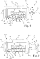
- Each respective return path 150-1, 150-2 facilitates a return of rack carrier 40 to the proximal position 40-1 (see Fig. 4 ) to reengage the plurality of racks 42 with the plurality of key followers 34, with the return being effected by biasing member 44 that is engaged with rack carrier 40 that continually tends to bias rack carrier 40 toward the proximal end 32-1 of plug body 32 to the proximal position 40-1.
- plug assembly 14 is rotatable in either the counterclockwise direction 152 or the clockwise direction 154 with rack carrier 40 remaining in the proximal position 40-1 until cam follower 130 reengages one of the diverging ramps of the V-shaped portion 144.
- Return path 150-1 is configured with a respective beveled side wall portion 156-1
- return path 150-2 is configured with a respective beveled side wall portion 156-2, to engage and depress cam follower 130 upon further rotation of plug assembly 14 relative to lock cylinder body 12 such that cam follower 130 leaves cam track 138, with rack carrier 40 in the proximal position 40-1, to travel along a neutral path 158, depicted by the horizontal dashed line in Fig. 11 .
- the neutral path 158 corresponds to the state of plug assembly 14 with rack carrier 40 in the proximal position 40-1.
- Cam follower 130 traveling along the neutral path 158, reengages cam track 138 when cam follower 130 reaches the apex 146 of the V-shaped portion 144 (home position HP) as plug assembly 14 is rotated relative to lock cylinder body 12.
- the present invention facilitates rekeying of lock cylinder 10 by a partial rotation of plug assembly 14 relative to lock cylinder body 12 in either of the counterclockwise direction 152 or clockwise direction 154, relative to the home position HP.
- rekeying may be limited to a rotation of plug assembly 14 in the counterclockwise direction 152 by elimination of the second ramp portion 140-1.
- rekeying may be limited to a rotation of plug assembly 14 in the clockwise direction 154 by elimination of the first ramp portion 140-2.
- the key followers 34 are biased to the bottom of guide channels 100 and, based on the cut of the valid key to be inserted into keyway 56, racks 42 are disposed at various positions in rack-receiving slots 118 of rack carrier 40 with racks 42 engaged with the key followers 34.
- locking bar 46 extends from rack carrier 40 to engage locking bar groove 30 in lock cylinder body 12 to prevent plug assembly 14 from rotating in lock cylinder body 12.
- bullet-shaped, rack-engaging features 78 are misaligned with the semi-circular recess 124 in racks 42 and therefore interfere with movement of racks 42 parallel to the longitudinal axis 18 of lock cylinder 10, preventing lock cylinder 10 from being rekeyed.
- the bullet-shaped, rack-engaging features 78 are aligned with the semi-circular recess 124 in racks 42, as illustrated in Fig. 2 , allowing racks 42, and rack carrier 40, to move parallel to the longitudinal axis 18 of lock cylinder 10.
- the valid key 58 is inserted into keyway 56, and plug assembly 14 is rotated approximately 20 to 60 degrees such that cam follower 130 travels along the respective ramp portion 140-1, 140-2 to the annular track portion 142, and may be retained by a respective detent feature 148-1, 148-2 in the annular track portion 142.
- rack carrier 40 is moved from the proximal position 40-1 to the distal position 40-2, thereby disengage racks 42 from the key followers 34.
- the semi-circular recesses 124 of the plurality of racks 42 are respectively engaged with the bullet-shaped, rack-engaging features 78 of plug body 32, which retains the longitudinal alignment of locking bar engaging grooves 122 of the plurality of racks 42 relative to locking bar 46 (see also Figs. 2 and 6A ).
- the valid key 58 is removed and replaced with a new key to which lock cylinder 10 is to be rekeyed.
- each of the plurality of key followers 34 is thus vertically positioned relative to the lift profile of the new key.
- the new key is rotated such that cam follower 130 returns to the neutral path 158, thereby returning rack carrier 40 to the proximal position 40-1, and in turn reengaging each of the plurality of key followers 34 with a respective rack of the plurality of racks 42.
- lock cylinder 10 is keyed to the new key and the previous valid key is no longer able to operate lock cylinder 10.
Landscapes
- Physics & Mathematics (AREA)
- Electromagnetism (AREA)
- Infusion, Injection, And Reservoir Apparatuses (AREA)
- Lock And Its Accessories (AREA)
- Fittings On The Vehicle Exterior For Carrying Loads, And Devices For Holding Or Mounting Articles (AREA)
- Manufacturing Of Electrical Connectors (AREA)
Claims (15)
- Schließzylinder (10) mit Neueingabemöglichkeit und einer longitudinalen Achse, umfassend:eine Steckanordnung (14) mit einem Steckkörper (32), eine Mehrzahl an Schlüsselfolgern (34), eine Mehrzahl an Stegen (42), und einem Steg-Träger (40), wobei der Steckkörper (32) einen Schlüsselkanal (56) aufweist, die hergerichtet ist, um einen Schlüssel (58) aufzunehmen, wobei die Mehrzahl an Schlüsselfolgern (34) beweglich im Steckkörper (32) angeordnet sind, wobei die Mehrzahl an Stegen (42) beweglich im Steg-Träger (40) angeordnet ist, wobei der Steckkörper (32) ein proximales Ende (32-1) und ein distales Ende (32-2) aufweist, wobei der Steg-Träger (40) bezüglich des Steckkörpers (32) zwischen dem proximalen Ende (32-1) und dem distalen Ende (32-2) longitudinal beweglich ist, wobei der Steg-Träger (40) einen Nockenfolger (130) aufweist, der sich vom Steg-Träger (40) nach außen erstreckt; undeinen Schließzylinderkörper (12) mit einer Zylinderwand (26), die eine innere Oberfläche (28) aufweist, welche einen inneren Hohlraum (20) festlegt, in welchem die Steckanordnung (14) rotierbar angeordnet ist, und einer Nockenspur (138), die auf der Zylinderwand (26) an der inneren Oberfläche (28) eingerichtet ist, um den Nockenfolger (130) der Steckanordnung (14) zu führen, wobei die Nockenspur (138) einen Rampenabschnitt (140) aufweist, der dazu hergerichtet ist, den Nockenfolger (130) und den Steg-Träger (40) longitudinal zu verschieben, während die Steckanordnung (14) um die longitudinale Achse bezüglich des Schließzylinderkörpers (12) rotiert wird, um ein selektives Absetzen der Mehrzahl an Stegen (42) von der Mehrzahl an Schlüsselfolgern (34) zu ermöglichen.
- Schließzylinder mit Neueingabemöglichkeit nach Anspruch 1, dadurch gekennzeichnet, dass dieser einen Schließriegel (46) umfasst, der innerhalb des Schließzylinderkörpers (12) angeordnet ist, und wobei jeder Steg der Mehrzahl an Stegen mindestens eine Schließriegelnut (30) aufweist, um den Schließriegel (46) selektiv aufzunehmen, und wobei der Schließriegel (46) und der Schließzylinderkörper (12) hergerichtet sind, um eine Rotation der Steckanordnung (14) bezüglich des Schließzylinderkörpers (12) zu verhindern, wenn ein ungültiger Schlüssel in den Schlüsselkanal (56) eingesetzt wird, und/oder
wobei der Steg-Träger (40) eine äußere Oberfläche (110) und eine versenkte Öffnung (134) aufweist, die sich in den Steg-Träger von der äußeren Oberfläche (110) erstreckt, wobei der Nockenfolger (130) in die versenkte Öffnung (134) eingesetzt ist, und ferner eine Feder (136) umfasst, die zwischen dem Steg-Träger (40) und dem Nockenfolger (130) positioniert ist, um den Nockenfolger (130) von der äußeren Oberfläche (110) nach außen weg von der longitudinalen Achse vorzuspannen, und/oder
der Schließzylinder (10) mit Neueingabemöglichkeit ferner ein Vorspannelement (44) umfasst, welches an dem Steg-Träger (40) angreift, um den Steg-Träger in Richtung des proximalen Endes der Steckanordnung (32) vorzuspannen. - Schließzylinder (10) mit Neueingabemöglichkeit nach einem der vorhergehenden Ansprüche, dadurch gekennzeichnet, dass der Steg-Träger (40) eine proximale Position (40-1) und eine distale Position (40-2) aufweist, wobei die proximale Position dem proximalen Ende des Steckkörpers (32) zugeordnet ist, wo die Mehrzahl an Stegen (42) an der Mehrzahl an Schlüsselfolgern (34) angreift, und wobei die distale Position dem distalen Ende des Steckkörpers (32) zugeordnet ist, wo die Mehrzahl an Stegen (42) von der Mehrzahl an Schlüsselfolgern (34) losgelöst ist.
- Schließzylinder (10) mit Neueingabemöglichkeit nach Anspruch 3, dadurch gekennzeichnet, dass der Rampenabschnitt (140) der Nockenspur (138) dazu hergerichtet ist, den Steg-Träger (40) in Richtung der distalen Position zu verschieben, während die Steckanordnung (14) um die longitudinale Achse bezüglich des Schließzylinderkörpers (12) rotiert wird.
- Schließzylinder (10) mit Neueingabemöglichkeit nach Anspruch 3, dadurch gekennzeichnet, dass die Nockenspur (138) eine Ausgangsposition (HP) und einen ringförmigen Spurabschnitt (142) aufweist, wobei sich der Rampenabschnitt (140) distal von der Ausgangsposition (HP) zum ringförmigen Spurabschnitt (142) erstreckt, wobei der ringförmige Spurabschnitt (142) einen distalen Bewegungsspielraum des Steg-Trägers (40) bezüglich des Steckkörpers (32) entsprechend der distalen Position (40-2) des Steg-Trägers festlegt, wobei der Nockenfolger (130) der Steckanordnung (14) den ringförmigen Spurabschnitt (142) nach einer Rotation der Steckanordnung (14) bezüglich der Ausgangsposition (HP) in einem Winkelbereich von 20 Grad bis 70 Grad bezüglich der Ausgangsposition (HP) erreicht.
- Schließzylinder (10) mit Neueingabemöglichkeit nach Anspruch 5, dadurch gekennzeichnet, dass die Ausgangsposition (HP) an der Basis des Rampenabschnitts (140) angeordnet ist, und eine Neueingabeposition (RP) auf dem ringförmigen Spurabschnitt durch einen Arretierungsabschnitt festlegt ist.
- Schließzylinder (10) mit Neueingabemöglichkeit nach Anspruch 5, dadurch gekennzeichnet, dass dieser ein Vorspannelement (44) umfasst, welches mit dem Steg-Träger (40) in Eingriff steht, um den Steg-Träger (40) in Richtung des proximalen Endes des Steckkörpers (32) vorzuspannen, und wobei die Nockenspur (138) einen Rücklaufpfad umfasst, welcher vom Rampenabschnitt (140) winkelversetzt ist, um den ringförmigen Spurabschnitt zu begrenzen, wobei, sobald der Nockenfolger (130) in den Rücklaufpfad eintritt, der Steg-Träger (40) vom Vorspannelement (44) von der distalen Position (40-2) zur proximalen Position (40-1) bewegt wird, um die Mehrzahl an Stegen (42) mit der Mehrzahl an Schlüsselfolgern (34) wieder in Eingriff zu bringen.
- Schließzylinder (10) mit Neueingabemöglichkeit nach Anspruch 7, dadurch gekennzeichnet, dass der Steg-Träger (40) eine äußere Oberfläche (110) und eine versenkte Öffnung (134) aufweist, die sich in den Steg-Träger (40) von der äußeren Oberfläche (110) aus erstreckt, wobei der Nockenfolger (130) in die versenkte Öffnung (134) eingesetzt wird, und ferner eine Vorspannfeder (136) umfasst, die den Nockenfolger (130) von der äußeren Oberfläche (110) aus nach außen hin vorspannt.
- Schließzylinder (10) mit Neueingabemöglichkeit nach Anspruch 8, dadurch gekennzeichnet, dass der Rücklaufpfad (150-1, 150-2) mit einem abgeschrägten Seitenwandabschnitt (156-1, 156-2) ausgebildet ist, um mit dem Nockenfolger (130) ineinander zu greifen und diesen bei einer weiteren Rotation der Steckanordnung (14) relativ zum Schließzylinderkörper (12) herunterzudrücken, so dass der Nockenfolger (130) die Nockenspur (138) mit dem Steg-Träger (40) in der proximalen Position (40-1) verlässt, wobei der Nockenfolger wieder in die Nockenspur (138) eingreift, wenn der Nockenfolger (130) die Ausgangsposition (HP) erreicht, während der Steckeinsatz (14) bezüglich des Schließzylinderkörpers (12) rotiert wird, und/oder
wobei der Rücklaufpfad (150-1, 150-2) mit einem abgeschrägten Seitenwandabschnitt (156-1, 156-2) ausgebildet ist, um an dem Nockenfolger (130) anzugreifen und diesen bei einer weiteren Rotation der Steckanordnung (14) bezüglich des Schließzylinderkörpers (12) herunterzudrücken, so dass, nachdem der Steg-Träger (40) in die proximale Position (40-1) zurückgekehrt ist, die Steckanordnung (14) rotierbar ist, wobei der Steg-Träger (40) in der proximalen Position (40-1) verbleibt, bis der Nockenfolger wieder mit dem Rampenabschnitt (140) ineinander greift. - Schließzylinder (10) mit Neueingabemöglichkeit nach Anspruch 3, dadurch gekennzeichnet, dass die Nockenspur (138) einen ringförmigen Spurabschnitt (142), einen V-förmigen Abschnitt (144) und eine Ausgangsposition (HP) aufweist, wobei der V-förmige Abschnitt (144) ein Paar divergierender Rampenabschnitte (140-1, 140-2) festlegt, wobei der Rampenabschnitt einen Rampenabschnitt des Paares divergierender Rampenabschnitte darstellt, wobei die Ausgangsposition (HP) an einem Scheitelpunkt des V-förmigen Abschnitts (144) angeordnet ist, wobei sich der V-förmige Abschnitt distal von der Ausgangsposition (HP) zum ringförmigen Spurabschnitt (142) erstreckt, wobei das Paar divergierender Rampenabschnitte (140-1, 140-2) der Nockenspur (138) hergerichtet ist, um den Steg-Träger (40) in Richtung der distalen Position (40-2) zu verschieben, während die Steckanordnung (14) um die longitudinale Achse bezüglich des Schließzylinderkörpers (12) rotiert wird.
- Schließzylinder (10) mit Neueingabemöglichkeit nach Anspruch 10, dadurch gekennzeichnet, dass der ringförmige Spurabschnitt (142) einen distalen Bewegungsspielraum des Steg-Trägers (40) entsprechend der distalen Position (40-2) festlegt, wobei der Nockenfolger (130) der Steckanordnung (14) den ringförmigen Spurabschnitt (142) nach einer Rotation der Steckanordnung (14) bezüglich der Ausgangsposition (HP) in einem Winkelbereich von 20 Grad bis 70 Grad entweder im Uhrzeigersinn oder gegen den Uhrzeigersinn bezüglich der Ausgangsposition (HP) erreicht.
- Schließzylinder (10) mit Neueingabemöglichkeit nach Anspruch 10, dadurch gekennzeichnet, dass das Paar divergierender Rampenabschnitte (140-1, 140-2) so angeordnet ist, dass eine Rotation der Steckanordnung (14) von der Ausgangsposition (HP) zu einer jeweiligen Neueingabeposition (RP) den Nockenfolger (130) veranlasst, sich entlang einer der divergierenden Rampenabschnitte zu bewegen, um im Gegenzug den Steg-Träger (40) von der proximalen Position (40-1) in Richtung der distalen Position (40-2) zu bewegen, um die Mehrzahl an Stegen (42) von der Mehrzahl an Schlüsselfolgern (34) loszulösen, um die Neueingabe des Schließzylinder (10) mit Neueingabemöglichkeit zu ermöglichen, wobei vorzugsweise jede der jeweiligen Neueingabepositionen (RP) im ringförmigen Spurabschnitt (142) durch ein jeweiliges Arretierungselement (148-1, 148-2) festgelegt ist.
- Schließzylinder (10) mit Neueingabemöglichkeit nach Anspruch 10, dadurch gekennzeichnet, dass dieser ein Vorspannelement (44) umfasst, das mit dem Steg-Träger (40) in Eingriff steht, um den Steg-Träger in Richtung des proximalen Endes des Steckkörpers (32) zur proximalen Position (40-1) vorzuspannen, und wobei der ringförmige Spurabschnitt (142) ein erstes ringförmiges Spursegment (142-1) und ein zweites ringförmiges Spursegment (142-2) umfasst, wobei jedes ringförmige Spursegment in einem entsprechenden Rücklaufpfad (150-1, 150-2) endet, der winkelversetzt zu einem des Paars divergierender Rampenabschnitte (140) ist, wobei jeder dieser Rücklaufpfade einen Rücklauf des Steg-Trägers (40) zur proximalen Position (40-1) ermöglicht, um die Mehrzahl an Stegen (42) mit der Mehrzahl an Schlüsselfolgern (34) wieder in Eingriff zu bringen.
- Schließzylinder (10) mit Neueingabemöglichkeit nach Anspruch 13, dadurch gekennzeichnet, dass der Steg-Träger (40) eine äußere Oberfläche (110) und eine versenkte Öffnung (134) aufweist, die sich in den Steg-Träger (40) von der äußeren Oberfläche (110) erstreckt, wobei der Nockenfolger (130) in die versenkte Öffnung (134) eingesetzt ist, und ferner eine Vorspannfeder (136) umfasst, die den Nockenfolger (130) von der äußeren Oberfläche (110) aus nach außen hin vorspannt.
- Schließzylinder (10) mit Neueingabemöglichkeit nach Anspruch 14, dadurch gekennzeichnet, dass jeder entsprechende Rücklaufpfad (150-1, 150-2) mit einem abgeschrägten Seitenwandabschnitt (156-1, 156-2) ausgebildet ist, um mit dem Nockenfolger (130) ineinander zu greifen und diesen bei einer weiteren Rotation der Steckanordnung (14) bezüglich des Schließzylinderkörpers (12) herunterzudrücken, so dass der Nockenfolger (130) die Nockenspur (138) mit dem Steg-Träger (40) in der proximalen Position (40-1) verlässt, wobei der Nockenfolger (130) wieder in die Nockenspur (138) eingreift, wenn der Nockenfolger (130) die Ausgangsposition (HP), während der Steckeinsatz (14) bezüglich des Schließzylinderkörpers (12) rotiert wird, erreicht und/oder
wobei jeder Rücklaufpfad (150-1, 150-2) mit einem abgeschrägten Seitenwandabschnitt (156-1, 156-2) ausgebildet ist, um an dem Nockenfolger (130) anzugreifen und diesen herunterzudrücken bei einer weiteren Rotation des Steckeinsatzes (14), so dass nachdem der Steg-Träger (40) zur proximalen Position (40-1) zurückgelaufen ist, der Steckeinsatz (14) entweder in einer Rotationsrichtung im Uhrzeigersinn oder in einer Rotationsrichtung entgegen dem Uhrzeigersinn rotierbar ist, wobei der Steg-Träger (40) in der proximalen Position (40-1) verweilt, bis der Nockenfolger (130) wieder mit einer der divergierenden Rampenabschnitte (140-1, 140-2) des V-förmigen Abschnitts (144) ineinander greift.
Applications Claiming Priority (2)
| Application Number | Priority Date | Filing Date | Title |
|---|---|---|---|
| US12/852,716 US8099988B1 (en) | 2010-08-09 | 2010-08-09 | Tool-less rekeyable lock cylinder |
| PCT/US2011/046681 WO2012021384A1 (en) | 2010-08-09 | 2011-08-05 | Tool-less rekeyable lock cylinder |
Publications (3)
| Publication Number | Publication Date |
|---|---|
| EP2603653A1 EP2603653A1 (de) | 2013-06-19 |
| EP2603653A4 EP2603653A4 (de) | 2016-08-17 |
| EP2603653B1 true EP2603653B1 (de) | 2018-03-28 |
Family
ID=45476726
Family Applications (1)
| Application Number | Title | Priority Date | Filing Date |
|---|---|---|---|
| EP11816848.3A Not-in-force EP2603653B1 (de) | 2010-08-09 | 2011-08-05 | Schliesszylinder mit werkzeugloser neueingabemöglichkeit |
Country Status (9)
| Country | Link |
|---|---|
| US (1) | US8099988B1 (de) |
| EP (1) | EP2603653B1 (de) |
| KR (1) | KR101386771B1 (de) |
| CN (1) | CN103210163B (de) |
| AR (1) | AR082589A1 (de) |
| AU (1) | AU2011289709B2 (de) |
| MX (1) | MX2013001499A (de) |
| PH (1) | PH12013500248B1 (de) |
| WO (1) | WO2012021384A1 (de) |
Families Citing this family (21)
| Publication number | Priority date | Publication date | Assignee | Title |
|---|---|---|---|---|
| US8316676B2 (en) * | 2008-08-29 | 2012-11-27 | Tong Lung Metal Industry Co., Ltd. | Re-keyable cylinder lock |
| US9234370B2 (en) * | 2011-02-21 | 2016-01-12 | Moshe Dolev | Key blank, key and cylinder lock with reduced costs |
| KR20130058350A (ko) * | 2011-11-25 | 2013-06-04 | 삼성전자주식회사 | 자동차 램프용 발광소자 모듈 |
| CN102720399B (zh) * | 2012-05-31 | 2014-10-22 | 浙江汇力锁业有限公司 | 新型防盗锁具 |
| US9169667B1 (en) | 2012-06-01 | 2015-10-27 | Louis A. O'Neill | Rekeying tool for a lock |
| US9127479B2 (en) | 2012-08-06 | 2015-09-08 | Kwikset Corporation | Rekeyable lock system |
| ITBO20120662A1 (it) | 2012-12-10 | 2014-06-11 | Filippo Bastianini | Serratura con ingegno a dischi riprogrammabile meccanicamente e chiave per la stessa |
| US9512638B2 (en) * | 2014-02-07 | 2016-12-06 | Schlage Lock Company Llc | Leaf spring lock cylinder |
| US9624696B2 (en) | 2014-06-04 | 2017-04-18 | Schlage Lock Company Llc | Lock plug including modular cartridges |
| US10612271B2 (en) | 2015-06-16 | 2020-04-07 | Spectrum Brands, Inc. | Rekeyable lock cylinder with enhanced torque resistance |
| CN109642437B (zh) * | 2016-09-01 | 2021-03-26 | 乌尔巴纳普斯有限公司 | 用于控制具有筒形插头的锁的钥匙和用于验证该钥匙的锁 |
| US11220840B1 (en) | 2018-07-31 | 2022-01-11 | Spectrum Brands, Inc. | Rekeyable lock with small increments |
| US12104404B2 (en) * | 2018-07-31 | 2024-10-01 | Assa Abloy Americas Residential Inc. | Rekeyable lock with small increments |
| TWI815940B (zh) | 2018-07-31 | 2023-09-21 | 美商品譜公司 | 具小增量之可重新換配鑰匙之鎖 |
| PL3623549T3 (pl) * | 2018-09-13 | 2022-02-28 | Talleres De Escoriaza, S.A.U. | Układ zamka z kluczem i wkładką bębenkową |
| US11319726B2 (en) | 2018-10-22 | 2022-05-03 | Spectrum Brands, Inc. | Tool-less rekeyable lock cylinder |
| US12421762B2 (en) | 2023-01-10 | 2025-09-23 | Assa Abloy Americas Residential Inc. | Rekeyable lock cylinder |
| TWI860901B (zh) * | 2023-11-24 | 2024-11-01 | 台灣福興工業股份有限公司 | 可更換鑰匙之鎖具 |
| US12492576B2 (en) | 2023-02-10 | 2025-12-09 | Taiwan Fu Hsing Industrial Co., Ltd. | Lockset |
| CA3227726A1 (en) | 2023-02-10 | 2025-04-29 | Taiwan Fu Hsing Industrial Co., Ltd. | Rekeyable lock |
| TWI864585B (zh) | 2023-02-10 | 2024-12-01 | 台灣福興工業股份有限公司 | 基於匹配多元鎖匙截面形狀之鎖心裝置、其鎖珠槽配置方法,及其對應之鎖匙 |
Family Cites Families (145)
| Publication number | Priority date | Publication date | Assignee | Title |
|---|---|---|---|---|
| US1565556A (en) | 1921-10-27 | 1925-12-15 | Jules A Fremon | Pin-tumbler lock |
| US1610224A (en) | 1924-01-04 | 1926-12-07 | Ace Lock Company | Lock |
| US1845867A (en) | 1929-12-13 | 1932-02-16 | Ellingson Elling | Master-key lock |
| US1965889A (en) | 1933-11-03 | 1934-07-10 | Briggs & Stratton Corp | Lock |
| US2194469A (en) | 1935-04-04 | 1940-03-26 | Jules A Fremon | Pin tumbler lock |
| US2232017A (en) | 1935-12-28 | 1941-02-18 | Yale & Towne Mfg Co | Lock |
| US2139842A (en) | 1937-02-13 | 1938-12-13 | Arthur W Miller | Lock |
| US2391832A (en) | 1943-02-05 | 1945-12-25 | Yale & Towne Mfg Co | Removable core cylinder |
| US2370862A (en) | 1943-08-04 | 1945-03-06 | Yale & Towne Mfg Co | Removable core cylinder |
| US2895323A (en) | 1954-04-05 | 1959-07-21 | Kennedy Ernest Norbert | Change key lock |
| US2977786A (en) | 1959-08-03 | 1961-04-04 | Schlage Lock Co | Pin tumbler cylinder lock |
| FR1290046A (fr) | 1961-02-24 | 1962-04-06 | Viro S P A | Serrure à double cylindre |
| US3190093A (en) | 1963-02-07 | 1965-06-22 | Schlage Lock Co | Pin tumbler cylinder and key system |
| US3149486A (en) | 1963-04-22 | 1964-09-22 | Russell | Collapsing cylinder bottom pin |
| US3183692A (en) | 1963-08-28 | 1965-05-18 | Yale & Towne Inc | Construction lock cylinder |
| US3261189A (en) | 1963-12-10 | 1966-07-19 | Best Frank Ellison | Single shear line lock |
| US3320781A (en) | 1964-08-28 | 1967-05-23 | Lewis J Hill | Key operated locks |
| US3293892A (en) | 1964-10-09 | 1966-12-27 | Independent Lock Co | Lock adapter |
| US3431757A (en) | 1966-09-05 | 1969-03-11 | Hideo Hori | Multiple key lock having change key mechanism |
| CH502495A (de) | 1968-11-30 | 1971-01-31 | Voss Kg J | Zylinderschloss |
| US3589153A (en) | 1970-02-16 | 1971-06-29 | Lewis J Hill | Key operated lock |
| US3693384A (en) | 1970-08-25 | 1972-09-26 | Joseph M Genakis | Step cam disc cylinder lock |
| CH532705A (it) | 1970-10-15 | 1973-01-15 | Motta Benito Di | Serratura a cilindro con spine diametrali registrabili |
| US3667262A (en) | 1971-01-11 | 1972-06-06 | Lewis J Hill | Key operated lock |
| CH537509A (fr) | 1971-02-24 | 1973-05-31 | Parlier Roger | Serrure à clé |
| US3735612A (en) | 1971-06-28 | 1973-05-29 | A Popovici | Double spring bolt re-keyable padlock |
| US3728880A (en) | 1972-02-10 | 1973-04-24 | Fort Lock Corp | Rekeyable axial pin tumbler lock |
| US3754422A (en) | 1972-06-26 | 1973-08-28 | American Locker Co | Cylinder lock and u-shaped key and method of forming same |
| CH576576A5 (de) | 1974-02-14 | 1976-06-15 | Rossetti Charles | |
| US3910083A (en) | 1974-03-01 | 1975-10-07 | Glen E Burlingame | Combination changing cylinder lock |
| CH577617A5 (de) | 1974-09-26 | 1976-07-15 | Bauer Kaba Ag | |
| US3999413A (en) | 1975-01-31 | 1976-12-28 | Raymond James W | Lock assembly |
| US3990282A (en) | 1975-06-24 | 1976-11-09 | Sorum Lorang N | Tumbler type lock |
| US4015458A (en) | 1975-11-21 | 1977-04-05 | Leonard Mercurio | Wafer type tumbler lock construction having individual side bar tumbler inhibiting means |
| US4142391A (en) | 1976-08-18 | 1979-03-06 | Paig Robert M | Re-keying locking kit and method thereof |
| GB1554877A (en) | 1976-09-22 | 1979-10-31 | Raymond J W | Lock assembly |
| US4069694A (en) | 1976-09-27 | 1978-01-24 | James W. Raymond | Resettable lock assembly for hotels, and the like |
| US4094175A (en) | 1976-12-20 | 1978-06-13 | Julius Pechner | Internal tumbler lock key change system |
| US4195504A (en) | 1978-08-10 | 1980-04-01 | Best Lock Corporation | Mortise lock adaptation to key-removable cores |
| DE2922431C2 (de) | 1979-06-01 | 1984-07-19 | Kiekert GmbH & Co KG, 5628 Heiligenhaus | Schließzylinder für Kraftfahrzeugtürverschlüsse |
| SE422480B (sv) | 1979-07-10 | 1982-03-08 | Gkn Stenman Ab | Cylinderlas nyckel till detta samt sett att tillverka nyckeln |
| US4377940A (en) | 1980-09-30 | 1983-03-29 | Richard Hucknall | Impression-resistant lock |
| US4372139A (en) | 1980-10-20 | 1983-02-08 | Laake Dennis L | Self-contained re-keyable lock |
| US4376382A (en) | 1980-12-01 | 1983-03-15 | James W. Raymond | Resettable lock assembly |
| US4404824A (en) | 1981-02-05 | 1983-09-20 | Lori Corporation | Side-bar lock |
| US4380163A (en) | 1981-09-08 | 1983-04-19 | Reder Kenneth J | Tamper-resistant lock |
| US4412437A (en) | 1981-12-07 | 1983-11-01 | Innovative Research Corporation | Rekeyable lock method and apparatus |
| US4440009A (en) | 1981-12-07 | 1984-04-03 | Innovative Research Corporation | Rekeyable lock method and apparatus |
| US5050412A (en) | 1985-05-21 | 1991-09-24 | Costruzioni Italiane Serrature Affini C.I.S.A. S.P.A. | Flat key cylinder lock with anti-burglar features |
| US4741188A (en) | 1985-07-16 | 1988-05-03 | Smith Jerry R | Rekeyable master and user lock system with high security features |
| IT1208841B (it) | 1985-12-19 | 1989-07-10 | Rielda Serrature Srl | Serratura a cilindro con chiave intercambiabile |
| US4723427A (en) | 1986-03-21 | 1988-02-09 | Medeco Security Locks Inc. | Symmetrical side bar lock and key therefor |
| US4712402A (en) | 1986-06-16 | 1987-12-15 | Monahan Brian J | Integrally and sequentially re-keyable lock apparatus and method |
| US4747281A (en) | 1986-07-02 | 1988-05-31 | Monahan Brian J | Randomly and integrally re-keyable lock apparatus and method |
| US4712401A (en) | 1986-07-02 | 1987-12-15 | Monahan Brian J | Randomly and integrally re-keyable lock apparatus and method |
| US4732023A (en) | 1986-08-15 | 1988-03-22 | Shen Chao C | Modifiable cylinder |
| US4689978A (en) | 1986-10-27 | 1987-09-01 | Drummond Robert L | Side bar wafer lock, an improved spring retainer for said lock, and a method of using said spring retainer in said lock |
| US4729231A (en) | 1986-12-29 | 1988-03-08 | Wu Tsay D | Changeable key type lock barrel |
| CA1303373C (en) | 1987-04-17 | 1992-06-16 | Frank Joseph Martin | Re-keyable pin tumbler drawer lock and pin tumbler cabinet door lock |
| US4765163A (en) | 1987-04-20 | 1988-08-23 | Yale Security Inc. | Front-loaded knob assembly |
| US4836002A (en) | 1987-07-01 | 1989-06-06 | Monahan Brian J | Programmable lock apparatus and method |
| US4850210A (en) | 1987-09-21 | 1989-07-25 | Richard S. Adler | Lock adjustable to operate with different keys |
| US5325690A (en) | 1987-09-21 | 1994-07-05 | Richard S. Adler | Lock adjustable to operate with different keys |
| US4794772A (en) | 1988-03-10 | 1989-01-03 | K.X.L. Manufacturing, Inc. | Axial wafer tumbler lock and key |
| US4909053A (en) | 1988-05-17 | 1990-03-20 | Liberty Telephone Communications, Inc. | High security door locking device |
| US4912953A (en) | 1988-09-29 | 1990-04-03 | National Lock Corporation | Re-keyable cylinder lock |
| RU2093653C1 (ru) | 1988-10-14 | 1997-10-20 | Давид Исаакович Шафиркин | Блокирующее кодовое устройство |
| US4966021A (en) | 1988-11-04 | 1990-10-30 | Masco Building Products Corp. | Reprogrammable lock and keys therefor |
| GB2228523B (en) * | 1989-02-23 | 1993-04-14 | Land Rover Uk Ltd | A locking mechanism |
| US4942749A (en) | 1989-06-26 | 1990-07-24 | Jacob Rabinow | Interchangeable key lock with rolling tumblers |
| US5000019A (en) | 1989-08-07 | 1991-03-19 | Foster Merle L | Cylinder lock and method for using same |
| US4996856A (en) | 1990-04-16 | 1991-03-05 | Lin Peir Kuen | Structure of cylinder lock |
| US5038589A (en) | 1990-05-22 | 1991-08-13 | Frank J. Martin Company | Rekeyable cam lock |
| US5044180A (en) | 1990-05-25 | 1991-09-03 | Master Lock Company | Rekeyable shrouded lock |
| US5010753A (en) | 1990-07-06 | 1991-04-30 | Lori Corporation | Interchangeable core lock |
| US5076081A (en) | 1990-07-06 | 1991-12-31 | Lori Corporation | Key for interchangable core lock |
| US5507162A (en) | 1990-10-11 | 1996-04-16 | Intellikey Corp. | Eurocylinder-type assembly for electronic lock and key system |
| US5044185A (en) | 1990-11-07 | 1991-09-03 | Green James R | Bypass key system and methods |
| US5088305A (en) | 1991-03-18 | 1992-02-18 | Fort Lock Corporation | Snap-in self holding disc tumbler construction |
| US5121619A (en) | 1991-07-31 | 1992-06-16 | Frank J. Martin Company | Speed release mechanism for cylinder and plug assembly for use with cabinet locks |
| DE4126160A1 (de) | 1991-08-07 | 1993-02-11 | Winkhaus Fa August | Schliesszylinder, insbesondere fuer einsteckschloesser |
| US5209088A (en) | 1991-08-08 | 1993-05-11 | Rimma Vaks | Changeable code lock |
| US5174136A (en) | 1991-10-04 | 1992-12-29 | Thwing Randy L | Dual function padlock with removable cylinder mechanism |
| US5211044A (en) | 1992-01-14 | 1993-05-18 | Kim Kwon W | Universal lock and key |
| US5233850A (en) | 1992-02-03 | 1993-08-10 | Marc Schroeder | Rekeyable lock system |
| SE502017C2 (sv) | 1992-07-06 | 1995-07-17 | Widen And Sandh Key Partners A | Cylinderlås-nyckelkombination, nyckel för sådan kombination, nyckelämne för framställning av dylik nyckel samt cylinderlås för ingående i kombinationen |
| US5291767A (en) | 1992-07-23 | 1994-03-08 | Best Lock Corporation | Protective lock cylinder mounting assembly |
| CA2109872C (en) | 1993-01-27 | 2004-07-27 | Ernst Keller | Web for a built-in double lock cylinder |
| US5431034A (en) | 1993-09-23 | 1995-07-11 | Tong-Lung Metal Industry Co., Ltd. | Cylinder lock with removable and replaceable key plug |
| JP3411358B2 (ja) | 1993-12-28 | 2003-05-26 | 株式会社アルファ | 可変コード型シリンダ錠 |
| CZ289889B6 (cs) | 1994-03-04 | 2002-04-17 | Ernst Keller | Uzavírací zařízení |
| US5428978A (en) | 1994-03-29 | 1995-07-04 | Alpha Corporation | Cylinder lock device resistible against unauthorized unlocking |
| DE4420372A1 (de) | 1994-06-10 | 1995-12-14 | Ymos Ag Ind Produkte | Schließsystem, insbesondere für Kraftfahrzeuge und Gebäudeausrüstungen |
| US5540071A (en) | 1995-02-16 | 1996-07-30 | Huf-North America Automotive Parts Manufacturing Corp. | Lock cylinder with a body having integral spring retainer |
| US5718136A (en) | 1995-08-31 | 1998-02-17 | Kaba High Security Locks Corporation | Lost key lock-out cylinder |
| US6564601B2 (en) | 1995-09-29 | 2003-05-20 | Hyatt Jr Richard G | Electromechanical cylinder plug |
| US5704234A (en) | 1995-10-11 | 1998-01-06 | Strattec Security Corporation | Cylinder lock incorporating a slam resistance pad |
| DE19544840A1 (de) | 1995-12-01 | 1997-06-05 | Valeo Deutschland Gmbh & Co | Zylinderschloß mit Zylinderkern und Zuhaltungen |
| DK0866906T3 (da) | 1995-12-11 | 1999-08-09 | Berchtold Ag Sea Schliess Syst | Låseindretning med en cylinderlås og en flad nøgle |
| AUPN890196A0 (en) | 1996-03-25 | 1996-04-18 | Australian Lock Company Pty Ltd | Removable plug lock |
| US5765417A (en) | 1996-04-03 | 1998-06-16 | U-Shin Ltd. | Free wheel lock cylinder |
| US5752400A (en) | 1996-10-07 | 1998-05-19 | Kim; Kwon W | Universal lock and key |
| IT1291177B1 (it) | 1997-03-10 | 1998-12-29 | Rielda Srl | Serratura a cilindro programmabile, provvista di chiavi maestre. |
| US5921123A (en) | 1997-04-18 | 1999-07-13 | Abus August Bremicker Soehne Ag | Rekeyable padlock |
| US5884512A (en) | 1997-12-04 | 1999-03-23 | Wayne; Kenneth | Multi-use lock housing and cylinder |
| US5979200A (en) | 1997-12-12 | 1999-11-09 | Compx International, Inc. | Axial pin tumbler removable core lock |
| IL124637A (en) | 1998-05-25 | 2001-07-24 | Mul T Lock Security Prod Ltd | Socket lock |
| US5921122A (en) | 1998-05-27 | 1999-07-13 | Taiwan Fu Hsing Industry Co. Ltd. | Device for preventing falling of upper pin tumblers of a lock during change of a lock core in the lock |
| US6079240A (en) | 1998-07-24 | 2000-06-27 | Arrow Lock Manufacturing Company | Modular removable core cylinder assembly |
| US6523382B1 (en) * | 1998-09-08 | 2003-02-25 | Strattec Security Corporation | Free wheeling lock assembly |
| US6134928A (en) | 1998-09-10 | 2000-10-24 | Kang; Samuel | Method and apparatus for decoding lock cylinders |
| US6047577A (en) | 1998-10-09 | 2000-04-11 | Klimas; Frank | Abnormal use indicator for door lock |
| US6029484A (en) | 1998-12-07 | 2000-02-29 | Jetton; James E. | Secure door handle |
| US5970760A (en) | 1999-01-11 | 1999-10-26 | Shen; Mu-Lin | Lock core-changeable type auxiliary lock with improved pull-resistant structure |
| US6295850B1 (en) | 1999-04-09 | 2001-10-02 | Loctec Corporation | Key-operated cylinder lock with removable plate tumbler container |
| US6142717A (en) | 1999-05-18 | 2000-11-07 | Staiger; William A. | Method and apparatus for re-keying a lock |
| CZ301779B6 (cs) | 2000-01-24 | 2010-06-23 | Otocný zamykací válecek, klíc a stavebnicový systém | |
| JP2001234648A (ja) | 2000-02-24 | 2001-08-31 | Nikkoo:Kk | シリンダー錠 |
| JP3709146B2 (ja) | 2000-03-09 | 2005-10-19 | 株式会社アルファ | シリンダ錠 |
| US6516643B1 (en) | 2000-06-09 | 2003-02-11 | Michael Cohnitz Olshausen | Pop-up, precision lock-cylinder that reveals at once, with visual and tactile cues, who else with a key has sought or gained entry |
| US6425274B1 (en) | 2000-07-31 | 2002-07-30 | Abus Usa | Rekeyable padlock with a lock cylinder having an enlarged viewing slot |
| US6532782B2 (en) | 2001-04-17 | 2003-03-18 | Ming-Hsiang Chiu | Detachable lock core |
| US6523378B2 (en) | 2001-05-09 | 2003-02-25 | Lambert Kuo | Push-lock |
| US6978647B2 (en) | 2001-07-02 | 2005-12-27 | Master Lock Company | Pick-resistant wafer tumbler lock with sidebars |
| US6776017B2 (en) | 2001-11-08 | 2004-08-17 | Ez Change Lock Company, Llc | Adaptable radial tumbler lock |
| CA2473531A1 (en) | 2002-01-03 | 2003-07-17 | Strattec Security Corporation | Vehicular lock apparatus and method |
| US7634930B2 (en) | 2002-01-03 | 2009-12-22 | Strattec Security Corporation | Lock apparatus and method |
| US6860131B2 (en) | 2002-09-26 | 2005-03-01 | Newfrey Llc | Rekeying a lock assembly |
| US6959569B2 (en) | 2002-09-26 | 2005-11-01 | Newfrey Llc | Re-keyable lock assembly |
| US6862909B2 (en) | 2002-09-26 | 2005-03-08 | Newfrey Llc | Devices, methods, and systems for keying a lock assembly |
| US7114357B2 (en) | 2002-09-26 | 2006-10-03 | Newfrey, Llc | Keying system and method |
| JP3776078B2 (ja) | 2002-10-15 | 2006-05-17 | タキゲン製造株式会社 | サイドバー方式の可変コード型シリンダー錠 |
| CA2517887C (en) * | 2003-03-04 | 2011-09-13 | Newfrey Llc | Rekeyable lock cylinder assembly with adjustable pin lengths |
| US20050132766A1 (en) | 2003-12-22 | 2005-06-23 | Milo Thomas K. | Lock assembly |
| US7475578B2 (en) | 2004-03-30 | 2009-01-13 | Nobilus, Llc | Door locking system conversion adapter |
| US7007528B2 (en) | 2004-04-01 | 2006-03-07 | Newfrey Llc | Re-keyable lock cylinder |
| US8881567B2 (en) * | 2005-10-21 | 2014-11-11 | Kwikset Corporation | Reset fixture for rekeyable lock assembly |
| US7428836B2 (en) | 2006-01-17 | 2008-09-30 | Zhen-Lin Yang | Door lock having reinforced strength |
| TW200842231A (en) * | 2007-04-24 | 2008-11-01 | Tong Lung Metal Ind Co Ltd | Lock apparatus capable of repeatedly setting key and method thereof |
| TW200900569A (en) * | 2007-06-25 | 2009-01-01 | Taiwan Fu Hsing Ind Co Ltd | A lock core capable of swiftly changing keys and the key changing method thereof |
| TW200844314A (en) * | 2007-05-11 | 2008-11-16 | Taiwan Fu Hsing Ind Co Ltd | Lock cylinder fitting to different keys and method for fitting a lock cylinder with different keys |
| WO2008156664A2 (en) | 2007-06-13 | 2008-12-24 | Schlage Lock Company | Programmable lock cylinder assembly |
| TWI345602B (en) * | 2007-06-15 | 2011-07-21 | Taiwan Fu Hsing Ind Co Ltd | Rekeyable lock cylinder structure ,plug assembly thereof,plug body of plug assembly,sliding block of plug assembly ,structured lower pins of pin groups and cylinder body |
| TWI340784B (en) * | 2007-09-26 | 2011-04-21 | Taiwan Fu Hsing Ind Co Ltd | A method for a rekeyable lock cylinder |
| US8316676B2 (en) * | 2008-08-29 | 2012-11-27 | Tong Lung Metal Industry Co., Ltd. | Re-keyable cylinder lock |
-
2010
- 2010-08-09 US US12/852,716 patent/US8099988B1/en active Active
-
2011
- 2011-08-05 EP EP11816848.3A patent/EP2603653B1/de not_active Not-in-force
- 2011-08-05 PH PH1/2013/500248A patent/PH12013500248B1/en unknown
- 2011-08-05 CN CN201180046582.1A patent/CN103210163B/zh not_active Expired - Fee Related
- 2011-08-05 AR ARP110102868 patent/AR082589A1/es active IP Right Grant
- 2011-08-05 AU AU2011289709A patent/AU2011289709B2/en not_active Ceased
- 2011-08-05 KR KR1020137004543A patent/KR101386771B1/ko not_active Expired - Fee Related
- 2011-08-05 WO PCT/US2011/046681 patent/WO2012021384A1/en not_active Ceased
- 2011-08-05 MX MX2013001499A patent/MX2013001499A/es active IP Right Grant
Non-Patent Citations (1)
| Title |
|---|
| None * |
Also Published As
| Publication number | Publication date |
|---|---|
| EP2603653A1 (de) | 2013-06-19 |
| US20120031156A1 (en) | 2012-02-09 |
| AR082589A1 (es) | 2012-12-19 |
| US8099988B1 (en) | 2012-01-24 |
| PH12013500248B1 (en) | 2017-12-15 |
| AU2011289709A1 (en) | 2013-02-28 |
| CN103210163B (zh) | 2016-04-27 |
| KR101386771B1 (ko) | 2014-04-21 |
| KR20130041258A (ko) | 2013-04-24 |
| MX2013001499A (es) | 2013-06-05 |
| CN103210163A (zh) | 2013-07-17 |
| AU2011289709B2 (en) | 2015-06-25 |
| HK1187662A1 (zh) | 2014-04-11 |
| PH12013500248A1 (en) | 2013-03-11 |
| EP2603653A4 (de) | 2016-08-17 |
| WO2012021384A1 (en) | 2012-02-16 |
Similar Documents
| Publication | Publication Date | Title |
|---|---|---|
| EP2603653B1 (de) | Schliesszylinder mit werkzeugloser neueingabemöglichkeit | |
| AU2003272612B2 (en) | Rekeyable lock assembly and method of operation | |
| US8033150B2 (en) | Rekeyable lock cylinder | |
| US8347678B2 (en) | Rekeyable lock cylinder assembly | |
| AU2004219671B2 (en) | Devices, methods, and systems for keying a lock assembly | |
| US20140041429A1 (en) | Rekeyable lock assembly with blown cylinder protection | |
| HK1187662B (en) | Tool-less rekeyable lock cylinder | |
| HK1084995B (en) | Rekeyable lock assembly and method of operation |
Legal Events
| Date | Code | Title | Description |
|---|---|---|---|
| PUAI | Public reference made under article 153(3) epc to a published international application that has entered the european phase |
Free format text: ORIGINAL CODE: 0009012 |
|
| 17P | Request for examination filed |
Effective date: 20130308 |
|
| AK | Designated contracting states |
Kind code of ref document: A1 Designated state(s): AL AT BE BG CH CY CZ DE DK EE ES FI FR GB GR HR HU IE IS IT LI LT LU LV MC MK MT NL NO PL PT RO RS SE SI SK SM TR |
|
| RIN1 | Information on inventor provided before grant (corrected) |
Inventor name: WHEATLAND, GRAHAM, J. |
|
| DAX | Request for extension of the european patent (deleted) | ||
| RA4 | Supplementary search report drawn up and despatched (corrected) |
Effective date: 20160714 |
|
| RIC1 | Information provided on ipc code assigned before grant |
Ipc: E05B 27/04 20060101AFI20160708BHEP Ipc: E05B 29/04 20060101ALI20160708BHEP |
|
| GRAP | Despatch of communication of intention to grant a patent |
Free format text: ORIGINAL CODE: EPIDOSNIGR1 |
|
| STAA | Information on the status of an ep patent application or granted ep patent |
Free format text: STATUS: GRANT OF PATENT IS INTENDED |
|
| INTG | Intention to grant announced |
Effective date: 20170725 |
|
| GRAS | Grant fee paid |
Free format text: ORIGINAL CODE: EPIDOSNIGR3 |
|
| GRAJ | Information related to disapproval of communication of intention to grant by the applicant or resumption of examination proceedings by the epo deleted |
Free format text: ORIGINAL CODE: EPIDOSDIGR1 |
|
| GRAL | Information related to payment of fee for publishing/printing deleted |
Free format text: ORIGINAL CODE: EPIDOSDIGR3 |
|
| STAA | Information on the status of an ep patent application or granted ep patent |
Free format text: STATUS: REQUEST FOR EXAMINATION WAS MADE |
|
| RAP1 | Party data changed (applicant data changed or rights of an application transferred) |
Owner name: SPECTRUM BRANDS, INC. |
|
| GRAR | Information related to intention to grant a patent recorded |
Free format text: ORIGINAL CODE: EPIDOSNIGR71 |
|
| INTC | Intention to grant announced (deleted) | ||
| STAA | Information on the status of an ep patent application or granted ep patent |
Free format text: STATUS: GRANT OF PATENT IS INTENDED |
|
| INTG | Intention to grant announced |
Effective date: 20180117 |
|
| GRAA | (expected) grant |
Free format text: ORIGINAL CODE: 0009210 |
|
| STAA | Information on the status of an ep patent application or granted ep patent |
Free format text: STATUS: THE PATENT HAS BEEN GRANTED |
|
| AK | Designated contracting states |
Kind code of ref document: B1 Designated state(s): AL AT BE BG CH CY CZ DE DK EE ES FI FR GB GR HR HU IE IS IT LI LT LU LV MC MK MT NL NO PL PT RO RS SE SI SK SM TR |
|
| REG | Reference to a national code |
Ref country code: GB Ref legal event code: FG4D |
|
| REG | Reference to a national code |
Ref country code: CH Ref legal event code: EP |
|
| REG | Reference to a national code |
Ref country code: AT Ref legal event code: REF Ref document number: 983595 Country of ref document: AT Kind code of ref document: T Effective date: 20180415 |
|
| REG | Reference to a national code |
Ref country code: IE Ref legal event code: FG4D |
|
| REG | Reference to a national code |
Ref country code: DE Ref legal event code: R096 Ref document number: 602011046978 Country of ref document: DE |
|
| PG25 | Lapsed in a contracting state [announced via postgrant information from national office to epo] |
Ref country code: NO Free format text: LAPSE BECAUSE OF FAILURE TO SUBMIT A TRANSLATION OF THE DESCRIPTION OR TO PAY THE FEE WITHIN THE PRESCRIBED TIME-LIMIT Effective date: 20180628 Ref country code: LT Free format text: LAPSE BECAUSE OF FAILURE TO SUBMIT A TRANSLATION OF THE DESCRIPTION OR TO PAY THE FEE WITHIN THE PRESCRIBED TIME-LIMIT Effective date: 20180328 Ref country code: HR Free format text: LAPSE BECAUSE OF FAILURE TO SUBMIT A TRANSLATION OF THE DESCRIPTION OR TO PAY THE FEE WITHIN THE PRESCRIBED TIME-LIMIT Effective date: 20180328 Ref country code: FI Free format text: LAPSE BECAUSE OF FAILURE TO SUBMIT A TRANSLATION OF THE DESCRIPTION OR TO PAY THE FEE WITHIN THE PRESCRIBED TIME-LIMIT Effective date: 20180328 |
|
| REG | Reference to a national code |
Ref country code: NL Ref legal event code: MP Effective date: 20180328 |
|
| REG | Reference to a national code |
Ref country code: LT Ref legal event code: MG4D |
|
| PG25 | Lapsed in a contracting state [announced via postgrant information from national office to epo] |
Ref country code: BG Free format text: LAPSE BECAUSE OF FAILURE TO SUBMIT A TRANSLATION OF THE DESCRIPTION OR TO PAY THE FEE WITHIN THE PRESCRIBED TIME-LIMIT Effective date: 20180628 Ref country code: GR Free format text: LAPSE BECAUSE OF FAILURE TO SUBMIT A TRANSLATION OF THE DESCRIPTION OR TO PAY THE FEE WITHIN THE PRESCRIBED TIME-LIMIT Effective date: 20180629 Ref country code: SE Free format text: LAPSE BECAUSE OF FAILURE TO SUBMIT A TRANSLATION OF THE DESCRIPTION OR TO PAY THE FEE WITHIN THE PRESCRIBED TIME-LIMIT Effective date: 20180328 Ref country code: LV Free format text: LAPSE BECAUSE OF FAILURE TO SUBMIT A TRANSLATION OF THE DESCRIPTION OR TO PAY THE FEE WITHIN THE PRESCRIBED TIME-LIMIT Effective date: 20180328 Ref country code: RS Free format text: LAPSE BECAUSE OF FAILURE TO SUBMIT A TRANSLATION OF THE DESCRIPTION OR TO PAY THE FEE WITHIN THE PRESCRIBED TIME-LIMIT Effective date: 20180328 |
|
| PG25 | Lapsed in a contracting state [announced via postgrant information from national office to epo] |
Ref country code: EE Free format text: LAPSE BECAUSE OF FAILURE TO SUBMIT A TRANSLATION OF THE DESCRIPTION OR TO PAY THE FEE WITHIN THE PRESCRIBED TIME-LIMIT Effective date: 20180328 Ref country code: PL Free format text: LAPSE BECAUSE OF FAILURE TO SUBMIT A TRANSLATION OF THE DESCRIPTION OR TO PAY THE FEE WITHIN THE PRESCRIBED TIME-LIMIT Effective date: 20180328 Ref country code: AL Free format text: LAPSE BECAUSE OF FAILURE TO SUBMIT A TRANSLATION OF THE DESCRIPTION OR TO PAY THE FEE WITHIN THE PRESCRIBED TIME-LIMIT Effective date: 20180328 Ref country code: ES Free format text: LAPSE BECAUSE OF FAILURE TO SUBMIT A TRANSLATION OF THE DESCRIPTION OR TO PAY THE FEE WITHIN THE PRESCRIBED TIME-LIMIT Effective date: 20180328 Ref country code: IT Free format text: LAPSE BECAUSE OF FAILURE TO SUBMIT A TRANSLATION OF THE DESCRIPTION OR TO PAY THE FEE WITHIN THE PRESCRIBED TIME-LIMIT Effective date: 20180328 Ref country code: RO Free format text: LAPSE BECAUSE OF FAILURE TO SUBMIT A TRANSLATION OF THE DESCRIPTION OR TO PAY THE FEE WITHIN THE PRESCRIBED TIME-LIMIT Effective date: 20180328 Ref country code: NL Free format text: LAPSE BECAUSE OF FAILURE TO SUBMIT A TRANSLATION OF THE DESCRIPTION OR TO PAY THE FEE WITHIN THE PRESCRIBED TIME-LIMIT Effective date: 20180328 |
|
| PG25 | Lapsed in a contracting state [announced via postgrant information from national office to epo] |
Ref country code: CZ Free format text: LAPSE BECAUSE OF FAILURE TO SUBMIT A TRANSLATION OF THE DESCRIPTION OR TO PAY THE FEE WITHIN THE PRESCRIBED TIME-LIMIT Effective date: 20180328 Ref country code: SM Free format text: LAPSE BECAUSE OF FAILURE TO SUBMIT A TRANSLATION OF THE DESCRIPTION OR TO PAY THE FEE WITHIN THE PRESCRIBED TIME-LIMIT Effective date: 20180328 Ref country code: SK Free format text: LAPSE BECAUSE OF FAILURE TO SUBMIT A TRANSLATION OF THE DESCRIPTION OR TO PAY THE FEE WITHIN THE PRESCRIBED TIME-LIMIT Effective date: 20180328 |
|
| REG | Reference to a national code |
Ref country code: AT Ref legal event code: MK05 Ref document number: 983595 Country of ref document: AT Kind code of ref document: T Effective date: 20180328 |
|
| PG25 | Lapsed in a contracting state [announced via postgrant information from national office to epo] |
Ref country code: PT Free format text: LAPSE BECAUSE OF FAILURE TO SUBMIT A TRANSLATION OF THE DESCRIPTION OR TO PAY THE FEE WITHIN THE PRESCRIBED TIME-LIMIT Effective date: 20180730 |
|
| REG | Reference to a national code |
Ref country code: DE Ref legal event code: R097 Ref document number: 602011046978 Country of ref document: DE |
|
| PG25 | Lapsed in a contracting state [announced via postgrant information from national office to epo] |
Ref country code: AT Free format text: LAPSE BECAUSE OF FAILURE TO SUBMIT A TRANSLATION OF THE DESCRIPTION OR TO PAY THE FEE WITHIN THE PRESCRIBED TIME-LIMIT Effective date: 20180328 Ref country code: DK Free format text: LAPSE BECAUSE OF FAILURE TO SUBMIT A TRANSLATION OF THE DESCRIPTION OR TO PAY THE FEE WITHIN THE PRESCRIBED TIME-LIMIT Effective date: 20180328 |
|
| PLBE | No opposition filed within time limit |
Free format text: ORIGINAL CODE: 0009261 |
|
| STAA | Information on the status of an ep patent application or granted ep patent |
Free format text: STATUS: NO OPPOSITION FILED WITHIN TIME LIMIT |
|
| REG | Reference to a national code |
Ref country code: DE Ref legal event code: R119 Ref document number: 602011046978 Country of ref document: DE |
|
| 26N | No opposition filed |
Effective date: 20190103 |
|
| PG25 | Lapsed in a contracting state [announced via postgrant information from national office to epo] |
Ref country code: MC Free format text: LAPSE BECAUSE OF FAILURE TO SUBMIT A TRANSLATION OF THE DESCRIPTION OR TO PAY THE FEE WITHIN THE PRESCRIBED TIME-LIMIT Effective date: 20180328 |
|
| REG | Reference to a national code |
Ref country code: CH Ref legal event code: PL |
|
| GBPC | Gb: european patent ceased through non-payment of renewal fee |
Effective date: 20180805 |
|
| PG25 | Lapsed in a contracting state [announced via postgrant information from national office to epo] |
Ref country code: CH Free format text: LAPSE BECAUSE OF NON-PAYMENT OF DUE FEES Effective date: 20180831 Ref country code: LU Free format text: LAPSE BECAUSE OF NON-PAYMENT OF DUE FEES Effective date: 20180805 Ref country code: LI Free format text: LAPSE BECAUSE OF NON-PAYMENT OF DUE FEES Effective date: 20180831 |
|
| REG | Reference to a national code |
Ref country code: BE Ref legal event code: MM Effective date: 20180831 |
|
| REG | Reference to a national code |
Ref country code: IE Ref legal event code: MM4A |
|
| PG25 | Lapsed in a contracting state [announced via postgrant information from national office to epo] |
Ref country code: SI Free format text: LAPSE BECAUSE OF FAILURE TO SUBMIT A TRANSLATION OF THE DESCRIPTION OR TO PAY THE FEE WITHIN THE PRESCRIBED TIME-LIMIT Effective date: 20180328 |
|
| PG25 | Lapsed in a contracting state [announced via postgrant information from national office to epo] |
Ref country code: DE Free format text: LAPSE BECAUSE OF NON-PAYMENT OF DUE FEES Effective date: 20190301 Ref country code: IE Free format text: LAPSE BECAUSE OF NON-PAYMENT OF DUE FEES Effective date: 20180805 |
|
| PG25 | Lapsed in a contracting state [announced via postgrant information from national office to epo] |
Ref country code: FR Free format text: LAPSE BECAUSE OF NON-PAYMENT OF DUE FEES Effective date: 20180831 Ref country code: BE Free format text: LAPSE BECAUSE OF NON-PAYMENT OF DUE FEES Effective date: 20180831 |
|
| PG25 | Lapsed in a contracting state [announced via postgrant information from national office to epo] |
Ref country code: GB Free format text: LAPSE BECAUSE OF NON-PAYMENT OF DUE FEES Effective date: 20180805 |
|
| PG25 | Lapsed in a contracting state [announced via postgrant information from national office to epo] |
Ref country code: MT Free format text: LAPSE BECAUSE OF NON-PAYMENT OF DUE FEES Effective date: 20180805 |
|
| PG25 | Lapsed in a contracting state [announced via postgrant information from national office to epo] |
Ref country code: TR Free format text: LAPSE BECAUSE OF FAILURE TO SUBMIT A TRANSLATION OF THE DESCRIPTION OR TO PAY THE FEE WITHIN THE PRESCRIBED TIME-LIMIT Effective date: 20180328 |
|
| PG25 | Lapsed in a contracting state [announced via postgrant information from national office to epo] |
Ref country code: HU Free format text: LAPSE BECAUSE OF FAILURE TO SUBMIT A TRANSLATION OF THE DESCRIPTION OR TO PAY THE FEE WITHIN THE PRESCRIBED TIME-LIMIT; INVALID AB INITIO Effective date: 20110805 |
|
| PG25 | Lapsed in a contracting state [announced via postgrant information from national office to epo] |
Ref country code: CY Free format text: LAPSE BECAUSE OF FAILURE TO SUBMIT A TRANSLATION OF THE DESCRIPTION OR TO PAY THE FEE WITHIN THE PRESCRIBED TIME-LIMIT Effective date: 20180328 Ref country code: MK Free format text: LAPSE BECAUSE OF NON-PAYMENT OF DUE FEES Effective date: 20180328 |
|
| PG25 | Lapsed in a contracting state [announced via postgrant information from national office to epo] |
Ref country code: IS Free format text: LAPSE BECAUSE OF FAILURE TO SUBMIT A TRANSLATION OF THE DESCRIPTION OR TO PAY THE FEE WITHIN THE PRESCRIBED TIME-LIMIT Effective date: 20180728 |