EP2604000B1 - Architecture de distribution de charge pour le traitement d'un trafic ip tunnélisé - Google Patents
Architecture de distribution de charge pour le traitement d'un trafic ip tunnélisé Download PDFInfo
- Publication number
- EP2604000B1 EP2604000B1 EP10744535.5A EP10744535A EP2604000B1 EP 2604000 B1 EP2604000 B1 EP 2604000B1 EP 10744535 A EP10744535 A EP 10744535A EP 2604000 B1 EP2604000 B1 EP 2604000B1
- Authority
- EP
- European Patent Office
- Prior art keywords
- ethernet
- tunnelled
- packet
- traffic
- ethernet based
- Prior art date
- Legal status (The legal status is an assumption and is not a legal conclusion. Google has not performed a legal analysis and makes no representation as to the accuracy of the status listed.)
- Active
Links
Images



Classifications
-
- H—ELECTRICITY
- H04—ELECTRIC COMMUNICATION TECHNIQUE
- H04L—TRANSMISSION OF DIGITAL INFORMATION, e.g. TELEGRAPHIC COMMUNICATION
- H04L45/00—Routing or path finding of packets in data switching networks
- H04L45/70—Routing based on monitoring results
-
- H—ELECTRICITY
- H04—ELECTRIC COMMUNICATION TECHNIQUE
- H04L—TRANSMISSION OF DIGITAL INFORMATION, e.g. TELEGRAPHIC COMMUNICATION
- H04L12/00—Data switching networks
- H04L12/28—Data switching networks characterised by path configuration, e.g. LAN [Local Area Networks] or WAN [Wide Area Networks]
- H04L12/46—Interconnection of networks
- H04L12/4633—Interconnection of networks using encapsulation techniques, e.g. tunneling
-
- H—ELECTRICITY
- H04—ELECTRIC COMMUNICATION TECHNIQUE
- H04L—TRANSMISSION OF DIGITAL INFORMATION, e.g. TELEGRAPHIC COMMUNICATION
- H04L43/00—Arrangements for monitoring or testing data switching networks
- H04L43/02—Capturing of monitoring data
- H04L43/028—Capturing of monitoring data by filtering
-
- H—ELECTRICITY
- H04—ELECTRIC COMMUNICATION TECHNIQUE
- H04L—TRANSMISSION OF DIGITAL INFORMATION, e.g. TELEGRAPHIC COMMUNICATION
- H04L43/00—Arrangements for monitoring or testing data switching networks
- H04L43/12—Network monitoring probes
-
- H—ELECTRICITY
- H04—ELECTRIC COMMUNICATION TECHNIQUE
- H04L—TRANSMISSION OF DIGITAL INFORMATION, e.g. TELEGRAPHIC COMMUNICATION
- H04L47/00—Traffic control in data switching networks
- H04L47/10—Flow control; Congestion control
- H04L47/12—Avoiding congestion; Recovering from congestion
- H04L47/125—Avoiding congestion; Recovering from congestion by balancing the load, e.g. traffic engineering
-
- H—ELECTRICITY
- H04—ELECTRIC COMMUNICATION TECHNIQUE
- H04L—TRANSMISSION OF DIGITAL INFORMATION, e.g. TELEGRAPHIC COMMUNICATION
- H04L47/00—Traffic control in data switching networks
- H04L47/10—Flow control; Congestion control
- H04L47/32—Flow control; Congestion control by discarding or delaying data units, e.g. packets or frames
-
- H—ELECTRICITY
- H04—ELECTRIC COMMUNICATION TECHNIQUE
- H04L—TRANSMISSION OF DIGITAL INFORMATION, e.g. TELEGRAPHIC COMMUNICATION
- H04L63/00—Network architectures or network communication protocols for network security
- H04L63/14—Network architectures or network communication protocols for network security for detecting or protecting against malicious traffic
- H04L63/1408—Network architectures or network communication protocols for network security for detecting or protecting against malicious traffic by monitoring network traffic
-
- H—ELECTRICITY
- H04—ELECTRIC COMMUNICATION TECHNIQUE
- H04L—TRANSMISSION OF DIGITAL INFORMATION, e.g. TELEGRAPHIC COMMUNICATION
- H04L67/00—Network arrangements or protocols for supporting network services or applications
- H04L67/50—Network services
- H04L67/56—Provisioning of proxy services
- H04L67/563—Data redirection of data network streams
-
- H—ELECTRICITY
- H04—ELECTRIC COMMUNICATION TECHNIQUE
- H04L—TRANSMISSION OF DIGITAL INFORMATION, e.g. TELEGRAPHIC COMMUNICATION
- H04L63/00—Network architectures or network communication protocols for network security
- H04L63/02—Network architectures or network communication protocols for network security for separating internal from external traffic, e.g. firewalls
- H04L63/0209—Architectural arrangements, e.g. perimeter networks or demilitarized zones
- H04L63/0218—Distributed architectures, e.g. distributed firewalls
Definitions
- the invention generally relates the field of processing and monitoring tunnelled Internet Protocol (IP) traffic. More specifically, the invention relates to a technique for redirecting Ethernet based tunnelled IP traffic in an IP communications network for load distribution.
- IP Internet Protocol
- IP traffic monitoring systems include full-duplex taps which copy IP traffic and send the copied packets to one or more processors for analysis while the original traffic maintains intact.
- some single processors may not be capable of processing high bandwidth IP traffic streams in real time or near real time, as is necessary for many applications.
- some systems split high bandwidth IP streams among a plurality of processors based on each packet's address information.
- This information can include a packet's source or destination IP address, Transmission Control Protocol (TCP) or User Datagram Protocol (UDP) port values, or its Stream Control Transmission Protocol (SCTP) information.
- TCP Transmission Control Protocol
- UDP User Datagram Protocol
- SCTP Stream Control Transmission Protocol
- IP traffic monitoring systems rely upon each monitored packet being uniquely identifiable. In many cases, this is accomplished via each packet's IP and TCP, UDP, or SCTP address information.
- Tunnelling is a special form of encapsulation which ensures that user traffic is routed as per internal policies in the IP access network while the original packets are kept intact.
- GPRS General Packet Radio Service
- GTP General Packet Radio Service Tunnelling Protocol
- signalling message packets are tunnelled such that each packet includes the same outer IP address and/or TCP, UDP, or SCTP port information.
- processor selection is performed on the basis of the outer IP address (and/or TCP, UDP, or SCTP port information) the same processor would be selected for each packet, which would lead to an overload or at least to an extremely high load at the selected processor.
- the outer IP addresses and TCP, UDP, or SCTP header information are not usable to segregate traffic into multiple streams for splitting the traffic among a plurality of processors.
- a single network monitoring processor may be required to process all signalling message packets sent through the same tunnel. This may result in the processor being overwhelmed in current high speed networks.
- DPI Deep Packet Inspection
- non-header content typically the actual payload
- This is usually performed as the packet passes an inspection point, searching for protocol non-compliance, viruses, spam, intrusions or predefined criteria to decide what actions to take on the packet, including collecting statistical information.
- shallow packet inspection usually called Stateful Packet Inspection
- Commodity network elements such as network switches, routers or the like, are, however, limited for the inspection of Layer2/Layer3/Layer4 (Data Link Layer/Network Layer/Transport Layer) protocol parameters but not tunnel parameters.
- Layer2/Layer3/Layer4 Data Link Layer/Network Layer/Transport Layer
- US 2008/0031141 A1 proposes to distribute the packets among multiple processors within the monitoring device.
- the incoming packets arrive at a distributor function which selects the processor based on the header attributes of the inner user IP packet, typically based on the source and destination address.
- the limitation of this method is that it scales only as per the processors and memory can be put into one single node.
- US 2010/142371 A1 may be construed to disclose methods of balancing network packet traffic among multiple checking functionalities (CFs).
- a network has at least one client operatively connected to at least one source switch and multiple available CFs operatively connected to at least one destination switch. Each available CF has predetermined, but possibly different inspection capabilities.
- a source switch receiving packets from a client inspects each packet and can optionally choose an available CF having at least the minimum necessary inspection capabilities to inspect the particular packet, and tunnel the packet to the chosen CF.
- a parallel architecture for stateful intrusion detection in high traffic networks may be construed to disclose a parallel NIDS architecture.
- the load balancing mechanism of the proposed NIDS distributes the traffic among a configurable number of parallel sensors, so that each of them is reached by a manageable amount of traffic.
- the parallelism and traffic distribution do not alter the results of the traffic analysis that remains reliable and stateful.
- Shunting A Hardware/Software Architecture for. Flexible, High-Performance Network Intrusion Prevention
- J. Gonzalez, N. Weaver and V. Paxson Proceedings of the 14th ACM conference on Computer and communications security
- the architecture splits processing into a relatively simple, table-driven hardware device that processes the entire traffic stream inline, and a flexible analyzer (the IPS proper) that can run separately, communicating with the device either over a local bus or a dedicated Gbps Ethernet link.
- the present invention may be practiced in other embodiments that depart from these specific details.
- the exemplary embodiments are described in connection with Ethernet taps and Ethernet switches to illustrate the present invention, they are equally applicable to other kinds of tapping and switching techniques.
- the invention may be practiced in any network to which mobile and/or stationary users may attach.
- the present invention is applicable to, besides cellular networks, computer networks, Wireless Local Area Networks (WLANs), or similar wireless networks, but also to wireline networks such as, for example, the intranet of a company with some or many separated subsidiaries or the Internet.
- WLANs Wireless Local Area Networks
- the term node used hereinbelow may be any kind of network node capable of communicating over an IP communications network.
- the first and second nodes may be a GPRS Support Node (GSN) which supports the use of GPRS in the GSM core network or other core networks.
- the first node may be a Serving GPRS Support Node (SGSN) which is responsible for the delivery of data packets from and to mobile stations within its service area.
- the second node may be a Gateway GPRS Support Node (GGSN) which is responsible for the interworking between the GPRS network and external packet switched networks, like the Internet and X.25 networks.
- the functions explained herein below may be implemented using hardware circuitry, software means, or a combination thereof.
- the software means may be in conjunction with a programmed microprocessor or a general purpose computer, using an Application Specific Integrated Circuit (ASIC) and/or Digital Signal Processors (DSPs).
- ASIC Application Specific Integrated Circuit
- DSPs Digital Signal Processors
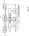
- FIG 1a a first system example for redirecting Ethernet based tunnelled IP traffic in an IP communications network is schematically illustrated.
- the system example comprises a first node 10 and a second node 20 which communicate with each over IP communications network.
- the first 10 and second nodes 20 may be implemented as a SGSN and a GGSN.
- the invention is not limited thereto.
- the system example further comprises a device 30 for redirecting the Ethernet based tunnelled IP traffic in the IP communications network.
- the system embodiment comprises an Ethernet switch 60 and a plurality of Processing Units PUs The Ethernet switch 60 and the plurality of PUs 50a, 50b, ..., 50z form a processing subsystem of the system embodiment.
- the Ethernet switch 60 may distribute the traffic to any number of PUs 50a, 50b, ..., 50z.
- the Ethernet switch 60 can distribute traffic among fifty to one hundred PUs 50a, 50b, ..., 50z (ports).
- two or more Ethernet switches 60 can be stacked such that e.g. one hundred to five hundred ports (PUs 50a, 50b, ..., 50z) can be effectively served.
- PUs 50a, 50b, ..., 50z may be served by the Ethernet switch 60.
- the traffic may only be distributed by the Ethernet switch 60 among only a small number of PUs 50a, 50b, ..., 50z, e.g. less than five PUs like four, three, two or even one PU.
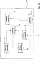
- the device 30 comprises a receiving component 32, a modifying component 34, a storage component 36, a selecting component 38, a restoring component 40 and a directing component 42.
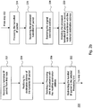
- FIG. 2a illustrates a first method example.
- the receiving component 32 of the device 30 receives an Ethernet based tunnelled IP packet transmitted from the first network node 10.
- the Ethernet based tunnelled IP packet includes a header and a payload, wherein the header contains an Ethernet destination Media Access Control (MAC) address.
- the Ethernet destination MAC address indicates that the Ethernet based tunnelled IP packet is addressed to the second node 20, i.e. the header of the Ethernet based tunnelled IP packet contains the address of the second node as the packet's address.
- the payload of the Ethernet based tunnelled IP packet contains an inner IP packet, i.e. the inner IP packet is encapsulated in the Ethernet based tunnelled IP packet.
- the inner IP packet includes an inner IP header and inner IP payload data.
- the modifying component 34 of the device 30 modifies the Ethernet destination MAC address contained in the header of the Ethernet based tunnelled IP packet on the basis of the inner IP header.
- the modification may be performed as follows: The modifying component 34 inspects the inner IP header of the inner IP packet and retrieves the destination address contained in the inner IP header.
- MAC learning is used by the modifying component to learn the MAC addresses of the plurality of PUs 50a, 50b, ..., 50z. After retrieving the destination address from the inner IP header and/or performing the MAC learning, the modifying component 34 rewrites the Ethernet destination MAC address of the Ethernet based tunnelled IP packet. For rewriting the Ethernet destination MAC address the modifying component 34 uses both the destination address retrieved from the inner IP header of the inner IP packet and one of the MAC addresses (of the PUs) learned during MAC learning.
- the modifying component may retrieve the original Ethernet destination MAC address from the header of the Ethernet based tunnelled IP packet and may store the original Ethernet destination MAC address in the storage component 36.
- the modifying component 34 may retrieve the Ethernet destination MAC address before or after retrieving the destination address from the inner IP header.
- the modifying component 34 may be adapted to concurrently retrieve the Ethernet destination MAC address from the header of the Ethernet based tunnelled IP packet and the destination address from the inner IP header of the inner IP packet.
- VLAN configuration As a further option (hereinbelow referred to as VLAN configuration), which may/may not be combined with the previous option, a Virtual Local Area Network (VLAN) configuration may be used.
- VLAN configuration each PU can be but into one VLAN so that the plurality of PUs 50a, 50b, ..., 50z is arranged in a plurality of VLANs independent from each other.
- a VLAN tag is signalled, from one PU to the device 30, so that the device 30 can locate the PU by also considering the VLAN tag.
- the header of the Ethernet based tunnelled IP packet further includes a VLAN tag and the PU is selected by not only considering the Ethernet destination address but by further considering the VLAN tag.
- the additional VLAN configuration in which each PU is put into one VLAN (statically configured in the Ethernet switch 60), the traffic between the Ethernet switch 60 and each PU can be isolated from each other because the VLANs (and thus the PUs) are independent from each other.
- the device 30, in accordance with this option has to modify not only the Ethernet destination MAC address, but also the VLAN tag associated with the corresponding PU.
- the selecting component 38 of the device 30 selects one of the PUs 50a, 50b, ..., 50z in accordance with the modified Ethernet destination MAC address.
- the second PU 50b is selected by the selecting component 38.
- the selecting component 38 of the device 30 selects one of the PUs 50a, 50b, ..., 50z in accordance with the modified Ethernet destination MAC address and the VLAN tag of the Ethernet based tunnelled IP packet.
- step 206 the selecting component of the device 30 selects the PU 50b from the plurality of PUs 50a, 50b, ..., 50z, because the PU 50b is indicated by the modified Ethernet destination MAC address.
- the selecting component 38 of the device 30 selects the PU 50b from the plurality of PUs 50a, 50b, ... 50z by not only considering the modified Ethernet destination MAC address, but by further considering the load of the plurality of PUs 50a, 50b, ... 50z.
- the selecting component 38 has knowledge about the respective load of each of the plurality of PUs 50a, 50b, ... 50z. This knowledge is obtained by the selecting component 38 such that each of the plurality of PUs 50a, 50b, ... 50z transmits a load indicator indicating its current load, i.e. the free capacity each PU currently has for packet processing.
- the selecting component 38 may deviate from the destination indicated by the modified Ethernet destination MAC address, because the PU (to which the packet is to be redirected in accordance with the modified Ethernet destination MAC address) does not have any or not sufficient capacities.
- the PU indicated by the modified Ethernet destination MAC address has sufficient capacities (i.e., the load is low enough for packet processing)
- the selecting component may select a different PU because the different PU has an even lower load or no load at all.
- the lowest reported load indicator may be used to select the PU for each new data session.
- Figure 2b illustrates a second method example.
- the steps 202, 204, 206 of figure 2b are equivalent to those of figure 2a .
- the second method example comprises the steps of the first method embodiment of figure 2a and further method steps 222 to 230.
- the Ethernet based tunnelled IP packet is redirected (in step 222), by the Ethernet switch 60, to the selected PU 50b.
- the selected PU 50b then, after receiving the redirected Ethernet based tunnelled IP packet, processes the Ethernet based tunnelled IP packet in step 224.
- a couple of different processing operations may be performed by the PU 50b. These processing operations include e.g. modifying, filtering or delaying the redirected Ethernet based tunnelled IP packet. Also a combination of different processing operations is possible, e.g. the PU 50b may, at first, filter the redirected Ethernet based tunnelled IP packet and may thereafter delay the filtered Ethernet based tunnelled IP packet.
- the PU 50b After processing the Ethernet based tunnelled IP packet in step 224, the PU 50b forwards the processed Ethernet based tunnelled IP packet to the Ethernet switch 60 which then itself forwards the processed Ethernet based tunnelled IP packet to the device 30, so that the device 30 receives the processed Ethernet based tunnelled IP packet in step 226.
- the restoring component 40 of the device 30 restores the original Ethernet destination MAC address in step 228.
- the restoring may be performed by retrieving the original Ethernet destination MAC address from the storage component 36 and by rewriting the original Ethernet destination MAC address in the header of the Ethernet based tunnelled IP packet based on the retrieved original Ethernet destination MAC address.
- the restoring component 40 of the device 30 does not only restore the original Ethernet destination MAC address, but also the VLAN tag of the Ethernet based tunnelled IP packet in step 228.
- the processed Ethernet based tunnelled IP packet is then finally directed (in step 230) by the directing component 42 of the device 30 to the second node 20 in accordance with the restored original Ethernet destination MAC address contained in the header of the Ethernet based tunnelled IP packet.
- the processed Ethernet based tunnelled IP packet is directed (in step 230) to the second node 20 by not only considering the restored original Ethernet destination MAC address contained in the header of the Ethernet based tunnelled IP packet, but also the VLAN tag contained in the header of the Ethernet based tunnelled IP packet.
- the original data flow between the first node 10 and the second node 20 is interrupted by the device 30 and routed through the processing subsystem.
- the invention splits the distribution and switching functions to achieve a scaleable processing architecture for Ethernet based tunnelled traffic, suitable for controlling purpose.
- the routing decision selection of the PU
- the routing decision selection of the PU
- the distribution of the traffic and thus the selection of the PU 50b is determined by the destination MAC address of the PU 50b.
- the actual switching is performed by the complementing Ethernet switch 60.
- the device 30 ensures that the packets of each data session select consistently the same PU, e.g. the selecting component 38 consistently selects the same second PU 50b for the packets of a first data session and the selecting component 38 consistently selects the same third PU 50c for the packets of a second data session.
- FIG 3a a system embodiment for redirecting Ethernet based tunnelled IP traffic in an IP communications network is schematically illustrated.
- components corresponding to those of figure 1a are provided with the same reference signs.
- system embodiment of figure 3a further comprises an Ethernet tap 70.
- Ethernet tap 70 any other device having similar functionality may be used, e.g. an Ethernet switch port mirroring device.
- Figure 3b shows a device 30 according to a device embodiment, which is configured differently than the first device example illustrated in figure 1b .
- the device 30 according to the device embodiment comprises a receiving component 32, a modifying component 34 and a selecting component 38.
- the device 30 according to the device embodiment does not necessarily have to comprise the storage component 36, the restoring component 40 and the directing component 42, but may comprise one or more of said components.
- FIG. 4a illustrates a first method embodiment.
- the Ethernet tap 70 receives an Ethernet based tunnelled IP packet transmitted from the first network node 10.
- the Ethernet based tunnelled IP packet includes a header and a payload, wherein the header contains an Ethernet destination MAC address (in the optional VLAN configuration, the header further contains a VLAN tag).
- the Ethernet destination MAC address indicates that the Ethernet tunnelled IP packet is addressed to the second node 20, i.e. the header of the Ethernet based tunnelled IP packet contains the address of the second node as the packet's address.
- the payload of the Ethernet based tunnelled IP packet contains an inner IP packet, i.e. the inner IP packet is encapsulated in the Ethernet based tunnelled IP packet.
- the inner IP packet includes an inner IP header and inner IP payload data.
- the Ethernet tap 70 copies the received Ethernet based tunnelled IP packet and forwards the copied Ethernet based tunnelled IP packet to the device 30.
- the Ethernet tap 70 forwards the unamended original Ethernet based tunnelled IP packet to the second node 20.
- the original traffic between the first node 10 and the second node 20 is left intact by the Ethernet tap 70, i.e. the original Ethernet based tunnelled IP packets received by the Ethernet tap 70 are forwarded to the second node 20 and the copied Ethernet based tunnelled IP packets are forwarded by the Ethernet tap 70 to the device 30.
- the receiving component 32 of the device 30 receives the copied Ethernet based tunnelled IP packet and forwards the packet to the modifying component 34 of the device 30.
- the modifying component 34 modifies the Ethernet destination MAC address contained in the header of the Ethernet based tunnelled IP packet on the basis of the inner IP header in step 406.
- the modification may be performed as follows:
- the modifying component 34 inspects the inner IP header of the inner IP packet and retrieves the destination address contained in the inner IP header.
- the modifying component 34 performs MAC learning and thus learns the MAC addresses of the plurality of PUs.
- the modifying component 34 After retrieving the destination address from the inner IP header, the modifying component 34 rewrites the Ethernet destination MAC address of the Ethernet based tunnelled IP packet based on the destination address retrieved from the inner IP header of the inner IP packet and the MAC address of one of the PUs.
- the Ethernet based tunnelled IP packet having the modified Ethernet destination address is then forwarded to the selecting component 38 of the device 30.
- the VLAN configuration can be used additionally and the VLAN tag has to be modified for addressing the appropriate PU in addition to the Ethernet destination MAC address.
- the selecting component 38 of the device 30 selects one (in the following exemplarily PU 50b is selected) of the PUs 50a, 50b, ..., 50z in accordance with the modified Ethernet destination MAC address.
- the selecting component 38 can either operate in static mode or in dynamic mode as set forth with respect to figures 1a , 1b , 2a and 2b above. Independent of whether the static or dynamic mode is used by the selecting component 38, one (the PU 50b) of the plurality of PUs 50a, 50b, ..., 50z is selected by the selecting component 38.
- the selecting component 38 of the device 30 selects one of the PUs 50a, 50b, ..., 50z in accordance with the modified Ethernet destination MAC address and the modified VLAN tag.
- Figure 4b illustrates a second method embodiment.
- the steps 402, 404, 406 and 408 of figure 4b are equivalent to those of figure 4a .
- the second method embodiment comprises steps 402 to 408 and the further steps 422 to 426.
- the selecting component 38 of the device 30 has selected the appropriate PU 50b either by using the static or dynamic mode in step 406, the Ethernet based tunnelled IP packet is redirected (in step 422), by the Ethernet switch 60, to the selected PU 50b.
- the selected PU 50b then, after receiving the Ethernet based tunnelled IP packet, monitors the Ethernet based tunnelled IP packet in step 424.
- a couple of different monitoring operations may be performed by the PU 50b. For example, the PU 50b collects statistical information related to the Ethernet based tunnelled IP packet.
- the PU 50b After monitoring the Ethernet based tunnelled IP packet in step 424, the PU 50b discards the monitored the Ethernet based tunnelled IP packet in step 426. Alternatively to discarding the Ethernet based tunnelled IP packet in step 426, the Ethernet based tunnelled IP packet may also be kept by the PU 50b e.g. for later monitoring operations.
- the original data flow between the first node 10 and the second node 20 is left intact by employing the Ethernet tap 70 to break-out the physical signal for monitoring purpose.
- the device 30 routes the duplicated (copied) frame to the appropriate PU 50b which eventually absorbs (discards) the traffic (no traffic is emitted back).
- the monitoring mode may be regarded as a subset of the controlling mode functionality where sending functions are disabled while the original traffic is left intact. Further, the user traffic is broken-out with the Ethernet tap 70 for monitoring purpose while the original traffic is left intact. The processing subsystem is then in listening mode only for maintaining various traffic statistics.
- FIG 5 summarizes the first system example of figure 1a , the first device example of figure 1b as well as the second method example of figure 2b (controlling mode).
- controlling mode the traffic originated from the first node 10 enters the device 30 through an input RX port.
- steps 202 to 206 (these steps are in the following summarized and referred to as R-FUNCTION)
- the device 30 performs the PU selection by rewriting the destination MAC address.
- the selected PU 50b then performs the controlling operation, e.g. the DPI task.
- the processed packets are directed back to the appropriate RX port of the device 30 (this step similar to step 226 is referred to as the M-FUNCTION).
- the packets received by the device 30 from the PU 50b are handled such that they are directed to the second node 20 in steps 228 and 230 (these steps are in the following summarized and referred to as T-FUNCTION, which may be regarded as a next-hop selection).
- the processed packets then leave the system through the TX ports towards the original destination, the second node 20.
- Figure 5 also illustrates a redirecting operation in the opposite direction, i.e. from the second node 20 to the first node 10. In the opposite redirecting operation all steps are equivalently performed in the opposite direction.
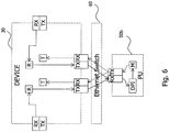
- FIG. 6 summarizes the system embodiment of figure 3a , the device embodiment of figure 3b as well as the second method embodiment of figure 4b (monitoring mode).
- the traffic originated from the first node 10 is duplicated by the external Ethernet tap 70 and the duplicated traffic enters the device 30 through an input RX port.
- steps 402, 406 and 408 (these steps are in the following summarized and referred to as R-FUNCTION), the device 30 performs the PU selection by rewriting the destination MAC address. Then, the packet is directed to the appropriate PU 50b. In the PU 50b, the packet is monitored for collecting statistical information about the traffic and is finally discarded.
- the T-FUNCTION and the M-FUNCTION as set forth above with respect to figure 5 may handle beacon frames.
- each PU can report its load and implicitly its status or health in periodic beacon frames to the device 30. These beacon frames may thus provide feedback between the PU and the device 30, which preferably must not be forwarded to the second node 20.
- the T-function advantageously filters the beacon frames used for load status update and may discard it. This may be used in both controlling and monitoring mode.
- the original packets are preferably not returned back to the device 30 and to the second node 20.
- the T-function will discard these packets.
- the T-function preferably forwards the returning packets to the second node 20.
- the R-FUNCTION ensures that the tunnelled IP packets (frames) sent by the nodes via the input (RX) ports are directed to the output (TX) ports of the processing subsystem.
- non-tunnelled frames may be directly passed to the T-FUNCTION to ensure transparency.
- the R-FUNCTION inspects the inner user IP header of the packet and rewrites the destination MAC address. The MAC addresses of the available PUs are automatically learnt using MAC learning.
- the R-FUNCTION may implement a stateful algorithm to ensure that subsequent packets of the same data session are directed to the same PU. In the dynamic mode, the lowest reported PU load indicator may be used to select the PU for each new data session. Overload protection is also feasible in that the excess traffic of new data sessions is directed immediately to the T-FUNCTION.
- the T-FUNCTION may be equivalent to the Address Resolution Protocol (ARP) mechanism (the MAC address resolution) which restores the destination MAC address of the original destination based on the outer destination IP address.
- ARP Address Resolution Protocol
- the T-FUNCTION ensures that the frames arriving back from the processing subsystem are directed to the appropriate outgoing (TX) port towards the nodes. It may also remove the beacon frames sent by the PUs and may update the list of available PUs for the R-FUNCTION.
- Each PU implements the M-FUNCTION, which ensures that the frame is returned to the appropriate port of the device 30. This purpose is achieved by swapping the source and destination MAC addresses of the packets before transmission back to the device 30. Furthermore, the M-FUNCTION may inject beacon frames periodically to inform the device 30 on the availability, the MAC address of the PU and on the processing load of the PU.
- Monitoring or controlling the tunnelled traffic has several benefits over the untunnelled traffic in 3GPP networks. For example, more factors can be incorporated for the decision. These include the bearer attributes, node location and several other parameters that are available from network signalling. This enables monitoring or controlling traffic for example at Gn, Iu, S1 interfaces of the 3GPP system.
- the introduction of the device 30 enables efficient scaling of the monitoring or controlling subsystem for tunnelled user traffic beyond the capabilities of hardware to be used in a single chassis. Further, the port density and stackable design of modern Ethernet switches enable the processing subsystem to be built from many low-speed, inexpensive components (PUs).
- PUs low-speed, inexpensive components
- the beacon based feedback mechanism ensures high-availability implementation of the processing subsystem and enables intelligent real-time overload protection at cost of reducing the data sessions to be inspected.
- the construction of the device 30 enables media conversion between few expensive inter-node links (e.g. 10Gbps Ethernet) and many inexpensive links (100/1000 Mbps Ethernet) of processing nodes. Furthermore, the one-to-one assignment of input and output ports ensures that there is no queuing and blocking within the device 30 and thus contribution to the latency and loss can be kept minimal.
- inter-node links e.g. 10Gbps Ethernet
- many inexpensive links 100/1000 Mbps Ethernet
Landscapes
- Engineering & Computer Science (AREA)
- Computer Networks & Wireless Communication (AREA)
- Signal Processing (AREA)
- Computer Security & Cryptography (AREA)
- Computer Hardware Design (AREA)
- Computing Systems (AREA)
- General Engineering & Computer Science (AREA)
- Data Exchanges In Wide-Area Networks (AREA)
Claims (12)
- Procédé de sélection d'une unité de traitement, PU, (50b) pour une analyse de trafic parmi une pluralité de PU (50a, 50b, ..., 50z), dans lequel un trafic de protocole Internet, IP, tunnellisé basé sur Ethernet comprenant un paquet IP tunnellisé basé sur Ethernet est transmis d'un premier noeud de réseau (10) par l'intermédiaire d'une prise Ethernet (70) à un deuxième noeud de réseau (20) d'un réseau de communication IP et le trafic IP tunnellisé basé sur Ethernet comprenant le paquet IP tunnellisé basé sur Ethernet doit être copié et le paquet IP tunnellisé basé sur Ethernet copié doit être redirigé dans le réseau de communication IP vers une PU sélectionnée (50b), et dans lequel la prise Ethernet (70) est reliée à la pluralité de PU (50a, 50b, ..., 50z) par l'intermédiaire d'un dispositif (30) et d'un commutateur Ethernet (60), le procédé comprenant les étapes de :- la copie (404), par la prise Ethernet, du trafic IP tunnellisé basé sur Ethernet comprenant le paquet IP tunnellisé basé sur Ethernet transmis du premier noeud de réseau (10), le transfert du paquet IP tunnellisé basé sur Ethernet copié au dispositif (30) et le transfert du paquet IP tunnellisé basé sur Ethernet d'origine non amendé au deuxième noeud (20) ;- la réception (402), par le dispositif (30) pour la sélection de la PU (50b) vers laquelle le trafic IP tunnellisé basé sur Ethernet doit être redirigé, du trafic IP tunnellisé basé sur Ethernet comprenant le paquet IP tunnellisé basé sur Ethernet copié du premier noeud de réseau (10), le paquet IP tunnellisé basé sur Ethernet comprenant un en-tête et une charge utile, l'en-tête contenant une adresse Ethernet de destination et la charge utile contenant un en-tête IP d'utilisateur interne d'un paquet IP d'utilisateur interne, dans lequel l'en-tête du paquet IP tunnellisé basé sur Ethernet comprend en outre une première étiquette de réseau local virtuel, VLAN ;- la réception, par le dispositif et en provenance de chacune de la pluralité de PU, d'une deuxième étiquette VLAN respective, dans lequel la pluralité de PU sont agencées dans une pluralité de VLAN indépendants l'un de l'autre de sorte que la deuxième étiquette VLAN indique une séparation logique de la pluralité de PU (50a, 50b, ..., 50z) en deux sous-ensembles ou plus de la pluralité de PU (50a, 50b, ..., 50z) ;- la modification (406), par le dispositif (30), de l'adresse Ethernet de destination et de la première étiquette VLAN contenues dans l'en-tête du paquet IP tunnellisé basé sur Ethernet copié sur la base de l'en-tête IP d'utilisateur interne, dans lequel la première étiquette VLAN modifiée est sélectionnée parmi un ensemble des deuxièmes étiquettes VLAN respectives associées à chaque PU ;- la sélection (408), par le dispositif (30), de la PU (50b) pour une analyse de trafic parmi la pluralité de PU (50a, 50b, ..., 50z), dans lequel le trafic IP tunnellisé basé sur Ethernet copié comprenant le paquet IP tunnellisé basé sur Ethernet doit être redirigé vers la PU sélectionnée en fonction de i) l'adresse Ethernet de destination modifiée et ii) la première étiquette VLAN modifiée ; et- la redirection (422), par le commutateur Ethernet (60), du trafic IP tunnellisé basé sur Ethernet copié comprenant le paquet IP tunnellisé basé sur Ethernet vers la PU sélectionnée (50b) en fonction de i) l'adresse Ethernet de destination modifiée et ii) la première étiquette VLAN modifiée, dans lequel le trafic entre le commutateur Ethernet et une première PU parmi la pluralité de PU est isolé du trafic entre le commutateur Ethernet et toute deuxième PU différente de la première PU.
- Procédé selon la revendication 1, dans lequel le procédé comprend en outre l'étape de la réception, par le dispositif (30), d'un ou plusieurs indicateurs de charge parmi la pluralité de PU (50a, 50b, ..., 50z), chaque indicateur de charge indiquant la charge de l'une de la pluralité de PU (50a, 50b, ..., 50z), et dans lequel la PU (50b) est sélectionnée en tenant compte de la charge de chacune de la pluralité de PU (50a, 50b, ..., 50z) tel que cela est indiqué par l'un ou plusieurs indicateurs de charge reçus.
- Procédé selon la revendication 2, dans lequel l'étape de la sélection (206, 408) comprend l'étape de la sélection, par le dispositif, de la PU ayant la plus faible charge parmi la pluralité de PU (50a, 50b, ..., 50z) sur la base de l'un ou plusieurs indicateurs de charge reçus ou la sélection, par le dispositif, d'aucune PU parmi la pluralité de PU (50a, 50b, ..., 50z) si l'un ou plusieurs indicateurs de charge reçus indiquent une surcharge dans la pluralité de PU (50a, 50b, ..., 50z).
- Procédé selon l'une quelconque des revendications 1 à 3, dans lequel le procédé comprend en outre les étapes de la surveillance (424) du paquet IP tunnellisé basé sur Ethernet dans la PU sélectionnée (50b) et, après l'étape de la surveillance (424), le rejet (426) du paquet IP tunnellisé basé sur Ethernet dans la PU sélectionnée (50b).
- Procédé selon la revendication 4, dans lequel l'étape de la surveillance (424) comprend l'étape de l'exécution d'une inspection profonde de paquet, DPI, sur le paquet IP tunnellisé basé sur Ethernet dans la PU sélectionnée (50b).
- Procédé selon l'une quelconque des revendications 1 à 3, le procédé comprenant en outre les étapes de :- le traitement (224) du paquet IP tunnellisé basé sur Ethernet dans la PU sélectionnée (50b) ;- la réception (226), par le dispositif (30), du paquet IP tunnellisé basé sur Ethernet traité ;- la restauration (228), par le dispositif (30), de l'adresse Ethernet de destination d'origine contenue dans le paquet IP tunnellisé basé sur Ethernet ; et- la direction (230), par le dispositif (30), du paquet IP tunnellisé basé sur Ethernet traité vers le deuxième noeud de réseau (20) en fonction de l'adresse Ethernet de destination d'origine restaurée.
- Procédé selon la revendication 6, dans lequel l'étape du traitement (224) comprend au moins l'un d'une modification, un filtrage et un retard du paquet IP tunnellisé basé sur Ethernet.
- Procédé selon l'une quelconque des revendications 1 à 7, dans lequel- le procédé comprend en outre l'étape de l'apprentissage automatique d'une pluralité d'adresses Ethernet de destination, dans lequel chaque adresse Ethernet de destination correspond à l'une de la pluralité de PU (50a, 50b, ..., 50z) ; et/ou- l'adresse Ethernet de destination est une adresse de commande d'accès au support, MAC.
- Produit de programme informatique comprenant des instructions qui, lorsqu'elles sont exécutées sur un processeur, amènent le processeur à exécuter toutes les étapes d'un procédé selon l'une quelconque des revendications 1 à 8.
- Produit de programme informatique selon la revendication 9, mémorisé sur un support d'enregistrement lisible par ordinateur.
- Système de redirection d'un trafic de protocole Internet, IP, tunnellisé basé sur Ethernet dans un réseau de communication IP, dans lequel le trafic IP tunnellisé basé sur Ethernet comprend un paquet IP tunnellisé basé sur Ethernet et est transmis d'un premier noeud de réseau (10) par l'intermédiaire d'une prise Ethernet (70) à un deuxième noeud de réseau (20) d'un réseau de communication IP et le trafic IP tunnellisé basé sur Ethernet comprenant le paquet IP tunnellisé basé sur Ethernet doit être copié et le paquet IP tunnellisé basé sur Ethernet copié doit être redirigé dans le réseau de communication IP vers une unité de traitement, PU, sélectionnée (50b), et dans lequel la prise Ethernet (70) est reliée à une pluralité de PU (50a, 50b, ..., 50z) par l'intermédiaire d'un dispositif (30) et d'un commutateur Ethernet (60), le système comprenant .- la pluralité de PU (50a, 50b, ..., 50z) pour une analyse de trafic ;- la prise Ethernet (70) étant apte à effectuer .-- la copie du trafic IP tunnellisé basé sur Ethernet reçu ;-- le transfert du paquet IP tunnellisé basé sur Ethernet copié au dispositif (30), et-- le transfert du paquet IP tunnellisé basé sur Ethernet d'origine non amendé au deuxième noeud (20) ;- le dispositif (30) comprenant :-- un composant de réception (32) apte à effectuer la réception de :--- le trafic IP tunnellisé basé sur Ethernet comprenant le paquet IP tunnellisé basé sur Ethernet copié transmis du premier noeud de réseau (10), le paquet IP tunnellisé basé sur Ethernet comprenant un en-tête et une charge utile, l'en-tête contenant une adresse Ethernet de destination et la charge utile contenant un en-tête IP d'utilisateur interne d'un paquet IP d'utilisateur interne, dans lequel l'en-tête du paquet IP tunnellisé basé sur Ethernet comprend en outre une première étiquette de réseau local virtuel, VLAN, et--- en provenance de chacune de la pluralité de PU, une deuxième étiquette VLAN respective, dans lequel la pluralité de PU sont agencées dans une pluralité de VLAN indépendants l'un de l'autre de sorte que la deuxième étiquette VLAN indique une séparation logique de la pluralité de PU (50a, 50b, ..., 50z) en deux sous-ensembles ou plus de la pluralité de PU (50a, 50b, ..., 50z) ;-- un composant de modification (34) apte à effectuer la modification de l'adresse Ethernet de destination et de la première étiquette VLAN contenues dans l'en-tête du paquet IP tunnellisé basé sur Ethernet copié sur la base de l'en-tête IP d'utilisateur interne par la sélection de la première étiquette VLAN modifiée parmi un ensemble des deuxièmes étiquettes VLAN respectives associées à chaque PU ; et-- un composant de sélection (38) apte à effectuer la sélection de la PU (50b) pour une analyse de trafic parmi la pluralité de PU (50a, 50b, ..., 50z), dans lequel le trafic IP tunnellisé basé sur Ethernet copié comprenant le paquet IP tunnellisé basé sur Ethernet doit être redirigé vers la PU sélectionnée (50b) en fonction de i) l'adresse Ethernet de destination modifiée et ii) la première étiquette VLAN modifiée ; et- le commutateur Ethernet (60) apte à effectuer la redirection du trafic IP tunnellisé basé sur Ethernet copié comprenant le paquet IP tunnellisé basé sur Ethernet vers la PU sélectionnée (50b) en fonction de i) l'adresse Ethernet de destination modifiée et ii) la première étiquette VLAN modifiée, dans lequel le trafic entre le commutateur Ethernet et une première PU parmi la pluralité de PU est isolé du trafic entre le commutateur Ethernet et toute deuxième PU différente de la première PU.
- Système selon la revendication 11, dans lequel le composant de modification (34) du dispositif (30) est en outre apte à effectuer la lecture de l'en-tête IP d'utilisateur interne du paquet IP d'utilisateur interne et la modification de l'adresse Ethernet de destination contenue dans l'en-tête du paquet IP tunnellisé basé sur Ethernet sur la base de l'en-tête IP d'utilisateur interne lue.
Applications Claiming Priority (1)
| Application Number | Priority Date | Filing Date | Title |
|---|---|---|---|
| PCT/EP2010/004999 WO2012019631A1 (fr) | 2010-08-13 | 2010-08-13 | Architecture de distribution de charge pour le traitement d'un trafic ip tunnélisé |
Publications (2)
| Publication Number | Publication Date |
|---|---|
| EP2604000A1 EP2604000A1 (fr) | 2013-06-19 |
| EP2604000B1 true EP2604000B1 (fr) | 2016-12-28 |
Family
ID=42732619
Family Applications (1)
| Application Number | Title | Priority Date | Filing Date |
|---|---|---|---|
| EP10744535.5A Active EP2604000B1 (fr) | 2010-08-13 | 2010-08-13 | Architecture de distribution de charge pour le traitement d'un trafic ip tunnélisé |
Country Status (3)
| Country | Link |
|---|---|
| US (2) | US9461912B2 (fr) |
| EP (1) | EP2604000B1 (fr) |
| WO (1) | WO2012019631A1 (fr) |
Cited By (1)
| Publication number | Priority date | Publication date | Assignee | Title |
|---|---|---|---|---|
| US20220174000A1 (en) * | 2020-12-01 | 2022-06-02 | Mellanox Technologies Tlv Ltd. | Routing with a fixed matchings switch |
Families Citing this family (30)
| Publication number | Priority date | Publication date | Assignee | Title |
|---|---|---|---|---|
| US20130215748A1 (en) * | 2012-02-21 | 2013-08-22 | Tektronix, Inc. | Intelligent and Scalable Network Monitoring Utilizing a Hierarchy of Devices |
| EP2928144B1 (fr) * | 2014-03-31 | 2016-11-02 | Sandvine Incorporated ULC | Système et procédé d'équilibrage de charge dans des réseaux informatiques |
| US9806998B2 (en) * | 2014-06-06 | 2017-10-31 | Extreme Networks, Inc. | Method of reducing traffic loss when bringing up a switch within a multi chassis switch cluster without using dedicated intra cluster links |
| WO2016089363A1 (fr) | 2014-12-02 | 2016-06-09 | Hewlett Packard Enterprise Development Lp | Acheminement d'insertion de services |
| US10198183B2 (en) * | 2015-02-06 | 2019-02-05 | Liqid Inc. | Tunneling of storage operations between storage nodes |
| WO2017091219A1 (fr) | 2015-11-25 | 2017-06-01 | Hewlett Packard Enterprise Development Lp | Réseau local virtuel de traitement |
| US10432531B2 (en) * | 2016-06-28 | 2019-10-01 | Paypal, Inc. | Tapping network data to perform load balancing |
| US9584381B1 (en) | 2016-10-10 | 2017-02-28 | Extrahop Networks, Inc. | Dynamic snapshot value by turn for continuous packet capture |
| US10476673B2 (en) | 2017-03-22 | 2019-11-12 | Extrahop Networks, Inc. | Managing session secrets for continuous packet capture systems |
| US20180324061A1 (en) * | 2017-05-03 | 2018-11-08 | Extrahop Networks, Inc. | Detecting network flow states for network traffic analysis |
| US9967292B1 (en) | 2017-10-25 | 2018-05-08 | Extrahop Networks, Inc. | Inline secret sharing |
| US10389574B1 (en) | 2018-02-07 | 2019-08-20 | Extrahop Networks, Inc. | Ranking alerts based on network monitoring |
| US10038611B1 (en) | 2018-02-08 | 2018-07-31 | Extrahop Networks, Inc. | Personalization of alerts based on network monitoring |
| US10270794B1 (en) | 2018-02-09 | 2019-04-23 | Extrahop Networks, Inc. | Detection of denial of service attacks |
| US10411978B1 (en) | 2018-08-09 | 2019-09-10 | Extrahop Networks, Inc. | Correlating causes and effects associated with network activity |
| US10594718B1 (en) | 2018-08-21 | 2020-03-17 | Extrahop Networks, Inc. | Managing incident response operations based on monitored network activity |
| US10965702B2 (en) | 2019-05-28 | 2021-03-30 | Extrahop Networks, Inc. | Detecting injection attacks using passive network monitoring |
| US11165814B2 (en) | 2019-07-29 | 2021-11-02 | Extrahop Networks, Inc. | Modifying triage information based on network monitoring |
| US10742530B1 (en) | 2019-08-05 | 2020-08-11 | Extrahop Networks, Inc. | Correlating network traffic that crosses opaque endpoints |
| US11388072B2 (en) | 2019-08-05 | 2022-07-12 | Extrahop Networks, Inc. | Correlating network traffic that crosses opaque endpoints |
| US10742677B1 (en) | 2019-09-04 | 2020-08-11 | Extrahop Networks, Inc. | Automatic determination of user roles and asset types based on network monitoring |
| US11165823B2 (en) | 2019-12-17 | 2021-11-02 | Extrahop Networks, Inc. | Automated preemptive polymorphic deception |
| US11463466B2 (en) | 2020-09-23 | 2022-10-04 | Extrahop Networks, Inc. | Monitoring encrypted network traffic |
| WO2022066910A1 (fr) | 2020-09-23 | 2022-03-31 | Extrahop Networks, Inc. | Surveillance de trafic réseau chiffré |
| CN112422444B (zh) * | 2020-10-09 | 2022-07-19 | 锐捷网络股份有限公司 | 一种报文跨卡转发的方法及装置 |
| US11349861B1 (en) | 2021-06-18 | 2022-05-31 | Extrahop Networks, Inc. | Identifying network entities based on beaconing activity |
| US11296967B1 (en) | 2021-09-23 | 2022-04-05 | Extrahop Networks, Inc. | Combining passive network analysis and active probing |
| US11843606B2 (en) | 2022-03-30 | 2023-12-12 | Extrahop Networks, Inc. | Detecting abnormal data access based on data similarity |
| US20260067250A1 (en) * | 2024-08-29 | 2026-03-05 | Arista Networks, Inc. | Exporting network flow information records using network storage |
| US12483384B1 (en) | 2025-04-16 | 2025-11-25 | Extrahop Networks, Inc. | Resynchronizing encrypted network traffic |
Family Cites Families (19)
| Publication number | Priority date | Publication date | Assignee | Title |
|---|---|---|---|---|
| US6999111B2 (en) | 2001-06-26 | 2006-02-14 | Eastman Kodak Company | Electronic camera and system for transmitting digital over a communication network |
| US7227867B1 (en) * | 2002-04-16 | 2007-06-05 | Juniper Networks, Inc. | Multi-protocol label switching in a network device |
| US7606229B1 (en) * | 2002-11-08 | 2009-10-20 | Cisco Technology, Inc. | Generic bridge packet tunneling |
| JP3880549B2 (ja) * | 2003-06-16 | 2007-02-14 | 松下電器産業株式会社 | 移動端末装置およびそのハンドオフ方法 |
| US7590725B1 (en) | 2003-07-01 | 2009-09-15 | Mcafee, Inc. | Network analyzer system, method and computer program product for multi-dimensional analysis of network tunnels |
| US20060203820A1 (en) * | 2004-01-16 | 2006-09-14 | Marc Coluccio | Method and system for communicating and isolating packetized data through a plurality of last-mile carriers to form a multi-node intranet |
| GB2414367B (en) * | 2004-05-20 | 2009-03-04 | Vodafone Plc | Data transmission |
| JP4401942B2 (ja) * | 2004-12-08 | 2010-01-20 | 株式会社日立コミュニケーションテクノロジー | パケット転送装置および通信ネットワーク |
| IN2005MU00878A (fr) | 2005-07-22 | 2009-06-29 | ||
| US7575171B2 (en) | 2005-09-01 | 2009-08-18 | Zvi Haim Lev | System and method for reliable content access using a cellular/wireless device with imaging capabilities |
| US8059646B2 (en) | 2006-07-11 | 2011-11-15 | Napo Enterprises, Llc | System and method for identifying music content in a P2P real time recommendation network |
| US9003056B2 (en) | 2006-07-11 | 2015-04-07 | Napo Enterprises, Llc | Maintaining a minimum level of real time media recommendations in the absence of online friends |
| US8179895B2 (en) | 2006-08-01 | 2012-05-15 | Tekelec | Methods, systems, and computer program products for monitoring tunneled internet protocol (IP) traffic on a high bandwidth IP network |
| US8248928B1 (en) * | 2007-10-09 | 2012-08-21 | Foundry Networks, Llc | Monitoring server load balancing |
| US20100008248A1 (en) * | 2008-07-08 | 2010-01-14 | Barry Constantine | Network tester for real-time measuring of tcp throughput |
| US7965636B2 (en) * | 2008-12-05 | 2011-06-21 | Hewlett-Packard Development Company, L.P. | Loadbalancing network traffic across multiple remote inspection devices |
| US8560583B2 (en) | 2010-04-01 | 2013-10-15 | Sony Computer Entertainment Inc. | Media fingerprinting for social networking |
| US9342817B2 (en) | 2011-07-07 | 2016-05-17 | Sony Interactive Entertainment LLC | Auto-creating groups for sharing photos |
| US10038650B2 (en) * | 2015-08-25 | 2018-07-31 | Futurewei Technologies, Inc. | System and method for tunnel stitching transport |
-
2010
- 2010-08-13 EP EP10744535.5A patent/EP2604000B1/fr active Active
- 2010-08-13 WO PCT/EP2010/004999 patent/WO2012019631A1/fr not_active Ceased
- 2010-08-13 US US13/811,318 patent/US9461912B2/en not_active Expired - Fee Related
-
2016
- 2016-08-30 US US15/250,994 patent/US10425328B2/en active Active
Non-Patent Citations (1)
| Title |
|---|
| MATTHIAS VALLENTIN ET AL: "The NIDS Cluster: Scalable, Stateful Network Intrusion Detection on Commodity Hardware", 5 September 2007, RECENT ADVANCES IN INTRUSION DETECTION; [LECTURE NOTES IN COMPUTER SCIENCE], SPRINGER BERLIN HEIDELBERG, BERLIN, HEIDELBERG, PAGE(S) 107 - 126, ISBN: 978-3-540-74319-4, XP019098105 * |
Cited By (2)
| Publication number | Priority date | Publication date | Assignee | Title |
|---|---|---|---|---|
| US20220174000A1 (en) * | 2020-12-01 | 2022-06-02 | Mellanox Technologies Tlv Ltd. | Routing with a fixed matchings switch |
| US12278755B2 (en) * | 2020-12-01 | 2025-04-15 | Mellanox Technologies, Ltd. | Routing with a fixed matchings switch |
Also Published As
| Publication number | Publication date |
|---|---|
| US9461912B2 (en) | 2016-10-04 |
| US20130212297A1 (en) | 2013-08-15 |
| US20160373350A1 (en) | 2016-12-22 |
| WO2012019631A1 (fr) | 2012-02-16 |
| EP2604000A1 (fr) | 2013-06-19 |
| US10425328B2 (en) | 2019-09-24 |
Similar Documents
| Publication | Publication Date | Title |
|---|---|---|
| EP2604000B1 (fr) | Architecture de distribution de charge pour le traitement d'un trafic ip tunnélisé | |
| US9998365B2 (en) | Network feedback in software-defined networks | |
| US11343182B2 (en) | System and method for dataplane-signaled packet capture in IPV6 environment | |
| Kruegel et al. | Stateful intrusion detection for high-speed network's | |
| US8553552B2 (en) | Stateless load balancer in a multi-node system for transparent processing with packet preservation | |
| US8458784B2 (en) | Data protection system selectively altering an end portion of packets based on incomplete determination of whether a packet is valid or invalid | |
| US8300532B1 (en) | Forwarding plane configuration for separation of services and forwarding in an integrated services router | |
| US7937761B1 (en) | Differential threat detection processing | |
| US9414136B2 (en) | Methods and apparatus to route fibre channel frames using reduced forwarding state on an FCoE-to-FC gateway | |
| US20120163391A1 (en) | Methods and apparatus for redundancy associated with a fibre channel over ethernet network | |
| US8472444B2 (en) | Method and apparatus for handling traffic in a data communication network | |
| US8605752B2 (en) | Communication apparatus, communication method, and computer program | |
| US10484199B2 (en) | Redundantly operable industrial communication system, method for operating the communication system, and radio transceiver station | |
| EP2823618A1 (fr) | Modification des communications de machine virtuelle | |
| US11252018B2 (en) | Service chaining with service path monitoring | |
| CN110557342A (zh) | 用于分析和减轻丢弃的分组的设备 | |
| JP5518754B2 (ja) | ネットワークノード | |
| CN104852855A (zh) | 拥塞控制方法、装置及设备 | |
| CN116527586B (zh) | 一种基于多链路负载均衡网络的串接代理系统 | |
| CN118555191B (zh) | 一种sf故障切换的方法和网络设备 | |
| JP2009206971A (ja) | 仮想lan用レイヤ2スイッチ装置、拡張ポーズフレーム、仮想lan輻輳防止方法およびプログラム | |
| KR20030018018A (ko) | 패킷 컨트롤 시스템과 방법 |
Legal Events
| Date | Code | Title | Description |
|---|---|---|---|
| PUAI | Public reference made under article 153(3) epc to a published international application that has entered the european phase |
Free format text: ORIGINAL CODE: 0009012 |
|
| 17P | Request for examination filed |
Effective date: 20130213 |
|
| AK | Designated contracting states |
Kind code of ref document: A1 Designated state(s): AL AT BE BG CH CY CZ DE DK EE ES FI FR GB GR HR HU IE IS IT LI LT LU LV MC MK MT NL NO PL PT RO SE SI SK SM TR |
|
| DAX | Request for extension of the european patent (deleted) | ||
| 17Q | First examination report despatched |
Effective date: 20150113 |
|
| REG | Reference to a national code |
Ref country code: DE Ref legal event code: R079 Ref document number: 602010039161 Country of ref document: DE Free format text: PREVIOUS MAIN CLASS: H04L0012260000 Ipc: H04L0029080000 |
|
| RIC1 | Information provided on ipc code assigned before grant |
Ipc: H04L 12/26 20060101ALI20160503BHEP Ipc: H04L 29/08 20060101AFI20160503BHEP Ipc: H04L 12/46 20060101ALI20160503BHEP Ipc: H04L 12/803 20130101ALI20160503BHEP Ipc: H04L 29/06 20060101ALI20160503BHEP Ipc: H04L 12/721 20130101ALI20160503BHEP |
|
| GRAP | Despatch of communication of intention to grant a patent |
Free format text: ORIGINAL CODE: EPIDOSNIGR1 |
|
| INTG | Intention to grant announced |
Effective date: 20160613 |
|
| GRAS | Grant fee paid |
Free format text: ORIGINAL CODE: EPIDOSNIGR3 |
|
| GRAA | (expected) grant |
Free format text: ORIGINAL CODE: 0009210 |
|
| AK | Designated contracting states |
Kind code of ref document: B1 Designated state(s): AL AT BE BG CH CY CZ DE DK EE ES FI FR GB GR HR HU IE IS IT LI LT LU LV MC MK MT NL NO PL PT RO SE SI SK SM TR |
|
| REG | Reference to a national code |
Ref country code: GB Ref legal event code: FG4D |
|
| REG | Reference to a national code |
Ref country code: CH Ref legal event code: EP |
|
| REG | Reference to a national code |
Ref country code: AT Ref legal event code: REF Ref document number: 858135 Country of ref document: AT Kind code of ref document: T Effective date: 20170115 |
|
| REG | Reference to a national code |
Ref country code: IE Ref legal event code: FG4D |
|
| REG | Reference to a national code |
Ref country code: DE Ref legal event code: R096 Ref document number: 602010039161 Country of ref document: DE |
|
| PG25 | Lapsed in a contracting state [announced via postgrant information from national office to epo] |
Ref country code: LV Free format text: LAPSE BECAUSE OF FAILURE TO SUBMIT A TRANSLATION OF THE DESCRIPTION OR TO PAY THE FEE WITHIN THE PRESCRIBED TIME-LIMIT Effective date: 20161228 |
|
| REG | Reference to a national code |
Ref country code: NL Ref legal event code: FP |
|
| REG | Reference to a national code |
Ref country code: LT Ref legal event code: MG4D |
|
| PG25 | Lapsed in a contracting state [announced via postgrant information from national office to epo] |
Ref country code: NO Free format text: LAPSE BECAUSE OF FAILURE TO SUBMIT A TRANSLATION OF THE DESCRIPTION OR TO PAY THE FEE WITHIN THE PRESCRIBED TIME-LIMIT Effective date: 20170328 Ref country code: LT Free format text: LAPSE BECAUSE OF FAILURE TO SUBMIT A TRANSLATION OF THE DESCRIPTION OR TO PAY THE FEE WITHIN THE PRESCRIBED TIME-LIMIT Effective date: 20161228 Ref country code: GR Free format text: LAPSE BECAUSE OF FAILURE TO SUBMIT A TRANSLATION OF THE DESCRIPTION OR TO PAY THE FEE WITHIN THE PRESCRIBED TIME-LIMIT Effective date: 20170329 Ref country code: SE Free format text: LAPSE BECAUSE OF FAILURE TO SUBMIT A TRANSLATION OF THE DESCRIPTION OR TO PAY THE FEE WITHIN THE PRESCRIBED TIME-LIMIT Effective date: 20161228 |
|
| REG | Reference to a national code |
Ref country code: AT Ref legal event code: MK05 Ref document number: 858135 Country of ref document: AT Kind code of ref document: T Effective date: 20161228 |
|
| PG25 | Lapsed in a contracting state [announced via postgrant information from national office to epo] |
Ref country code: HR Free format text: LAPSE BECAUSE OF FAILURE TO SUBMIT A TRANSLATION OF THE DESCRIPTION OR TO PAY THE FEE WITHIN THE PRESCRIBED TIME-LIMIT Effective date: 20161228 Ref country code: FI Free format text: LAPSE BECAUSE OF FAILURE TO SUBMIT A TRANSLATION OF THE DESCRIPTION OR TO PAY THE FEE WITHIN THE PRESCRIBED TIME-LIMIT Effective date: 20161228 |
|
| PG25 | Lapsed in a contracting state [announced via postgrant information from national office to epo] |
Ref country code: IS Free format text: LAPSE BECAUSE OF FAILURE TO SUBMIT A TRANSLATION OF THE DESCRIPTION OR TO PAY THE FEE WITHIN THE PRESCRIBED TIME-LIMIT Effective date: 20170428 Ref country code: CZ Free format text: LAPSE BECAUSE OF FAILURE TO SUBMIT A TRANSLATION OF THE DESCRIPTION OR TO PAY THE FEE WITHIN THE PRESCRIBED TIME-LIMIT Effective date: 20161228 Ref country code: SK Free format text: LAPSE BECAUSE OF FAILURE TO SUBMIT A TRANSLATION OF THE DESCRIPTION OR TO PAY THE FEE WITHIN THE PRESCRIBED TIME-LIMIT Effective date: 20161228 Ref country code: EE Free format text: LAPSE BECAUSE OF FAILURE TO SUBMIT A TRANSLATION OF THE DESCRIPTION OR TO PAY THE FEE WITHIN THE PRESCRIBED TIME-LIMIT Effective date: 20161228 Ref country code: RO Free format text: LAPSE BECAUSE OF FAILURE TO SUBMIT A TRANSLATION OF THE DESCRIPTION OR TO PAY THE FEE WITHIN THE PRESCRIBED TIME-LIMIT Effective date: 20161228 |
|
| PG25 | Lapsed in a contracting state [announced via postgrant information from national office to epo] |
Ref country code: SM Free format text: LAPSE BECAUSE OF FAILURE TO SUBMIT A TRANSLATION OF THE DESCRIPTION OR TO PAY THE FEE WITHIN THE PRESCRIBED TIME-LIMIT Effective date: 20161228 Ref country code: BE Free format text: LAPSE BECAUSE OF FAILURE TO SUBMIT A TRANSLATION OF THE DESCRIPTION OR TO PAY THE FEE WITHIN THE PRESCRIBED TIME-LIMIT Effective date: 20161228 Ref country code: IT Free format text: LAPSE BECAUSE OF FAILURE TO SUBMIT A TRANSLATION OF THE DESCRIPTION OR TO PAY THE FEE WITHIN THE PRESCRIBED TIME-LIMIT Effective date: 20161228 Ref country code: PT Free format text: LAPSE BECAUSE OF FAILURE TO SUBMIT A TRANSLATION OF THE DESCRIPTION OR TO PAY THE FEE WITHIN THE PRESCRIBED TIME-LIMIT Effective date: 20170428 Ref country code: AT Free format text: LAPSE BECAUSE OF FAILURE TO SUBMIT A TRANSLATION OF THE DESCRIPTION OR TO PAY THE FEE WITHIN THE PRESCRIBED TIME-LIMIT Effective date: 20161228 Ref country code: ES Free format text: LAPSE BECAUSE OF FAILURE TO SUBMIT A TRANSLATION OF THE DESCRIPTION OR TO PAY THE FEE WITHIN THE PRESCRIBED TIME-LIMIT Effective date: 20161228 Ref country code: BG Free format text: LAPSE BECAUSE OF FAILURE TO SUBMIT A TRANSLATION OF THE DESCRIPTION OR TO PAY THE FEE WITHIN THE PRESCRIBED TIME-LIMIT Effective date: 20170328 Ref country code: PL Free format text: LAPSE BECAUSE OF FAILURE TO SUBMIT A TRANSLATION OF THE DESCRIPTION OR TO PAY THE FEE WITHIN THE PRESCRIBED TIME-LIMIT Effective date: 20161228 |
|
| REG | Reference to a national code |
Ref country code: DE Ref legal event code: R097 Ref document number: 602010039161 Country of ref document: DE |
|
| PLBE | No opposition filed within time limit |
Free format text: ORIGINAL CODE: 0009261 |
|
| STAA | Information on the status of an ep patent application or granted ep patent |
Free format text: STATUS: NO OPPOSITION FILED WITHIN TIME LIMIT |
|
| PG25 | Lapsed in a contracting state [announced via postgrant information from national office to epo] |
Ref country code: DK Free format text: LAPSE BECAUSE OF FAILURE TO SUBMIT A TRANSLATION OF THE DESCRIPTION OR TO PAY THE FEE WITHIN THE PRESCRIBED TIME-LIMIT Effective date: 20161228 |
|
| 26N | No opposition filed |
Effective date: 20170929 |
|
| PG25 | Lapsed in a contracting state [announced via postgrant information from national office to epo] |
Ref country code: SI Free format text: LAPSE BECAUSE OF FAILURE TO SUBMIT A TRANSLATION OF THE DESCRIPTION OR TO PAY THE FEE WITHIN THE PRESCRIBED TIME-LIMIT Effective date: 20161228 |
|
| REG | Reference to a national code |
Ref country code: CH Ref legal event code: PL |
|
| PG25 | Lapsed in a contracting state [announced via postgrant information from national office to epo] |
Ref country code: MC Free format text: LAPSE BECAUSE OF FAILURE TO SUBMIT A TRANSLATION OF THE DESCRIPTION OR TO PAY THE FEE WITHIN THE PRESCRIBED TIME-LIMIT Effective date: 20161228 |
|
| PG25 | Lapsed in a contracting state [announced via postgrant information from national office to epo] |
Ref country code: CH Free format text: LAPSE BECAUSE OF NON-PAYMENT OF DUE FEES Effective date: 20170831 Ref country code: LI Free format text: LAPSE BECAUSE OF NON-PAYMENT OF DUE FEES Effective date: 20170831 |
|
| REG | Reference to a national code |
Ref country code: FR Ref legal event code: ST Effective date: 20180430 |
|
| REG | Reference to a national code |
Ref country code: IE Ref legal event code: MM4A |
|
| PG25 | Lapsed in a contracting state [announced via postgrant information from national office to epo] |
Ref country code: LU Free format text: LAPSE BECAUSE OF NON-PAYMENT OF DUE FEES Effective date: 20170813 |
|
| PG25 | Lapsed in a contracting state [announced via postgrant information from national office to epo] |
Ref country code: IE Free format text: LAPSE BECAUSE OF NON-PAYMENT OF DUE FEES Effective date: 20170813 |
|
| PG25 | Lapsed in a contracting state [announced via postgrant information from national office to epo] |
Ref country code: FR Free format text: LAPSE BECAUSE OF NON-PAYMENT OF DUE FEES Effective date: 20170831 |
|
| PG25 | Lapsed in a contracting state [announced via postgrant information from national office to epo] |
Ref country code: MT Free format text: LAPSE BECAUSE OF NON-PAYMENT OF DUE FEES Effective date: 20170813 |
|
| PG25 | Lapsed in a contracting state [announced via postgrant information from national office to epo] |
Ref country code: HU Free format text: LAPSE BECAUSE OF FAILURE TO SUBMIT A TRANSLATION OF THE DESCRIPTION OR TO PAY THE FEE WITHIN THE PRESCRIBED TIME-LIMIT; INVALID AB INITIO Effective date: 20100813 |
|
| PG25 | Lapsed in a contracting state [announced via postgrant information from national office to epo] |
Ref country code: CY Free format text: LAPSE BECAUSE OF NON-PAYMENT OF DUE FEES Effective date: 20161228 |
|
| PG25 | Lapsed in a contracting state [announced via postgrant information from national office to epo] |
Ref country code: MK Free format text: LAPSE BECAUSE OF FAILURE TO SUBMIT A TRANSLATION OF THE DESCRIPTION OR TO PAY THE FEE WITHIN THE PRESCRIBED TIME-LIMIT Effective date: 20161228 |
|
| PG25 | Lapsed in a contracting state [announced via postgrant information from national office to epo] |
Ref country code: TR Free format text: LAPSE BECAUSE OF FAILURE TO SUBMIT A TRANSLATION OF THE DESCRIPTION OR TO PAY THE FEE WITHIN THE PRESCRIBED TIME-LIMIT Effective date: 20161228 |
|
| PG25 | Lapsed in a contracting state [announced via postgrant information from national office to epo] |
Ref country code: AL Free format text: LAPSE BECAUSE OF FAILURE TO SUBMIT A TRANSLATION OF THE DESCRIPTION OR TO PAY THE FEE WITHIN THE PRESCRIBED TIME-LIMIT Effective date: 20161228 |
|
| PGFP | Annual fee paid to national office [announced via postgrant information from national office to epo] |
Ref country code: NL Payment date: 20210826 Year of fee payment: 12 |
|
| REG | Reference to a national code |
Ref country code: DE Ref legal event code: R079 Ref document number: 602010039161 Country of ref document: DE Free format text: PREVIOUS MAIN CLASS: H04L0029080000 Ipc: H04L0065000000 |
|
| PGFP | Annual fee paid to national office [announced via postgrant information from national office to epo] |
Ref country code: GB Payment date: 20210827 Year of fee payment: 12 |
|
| REG | Reference to a national code |
Ref country code: NL Ref legal event code: MM Effective date: 20220901 |
|
| GBPC | Gb: european patent ceased through non-payment of renewal fee |
Effective date: 20220813 |
|
| PG25 | Lapsed in a contracting state [announced via postgrant information from national office to epo] |
Ref country code: NL Free format text: LAPSE BECAUSE OF NON-PAYMENT OF DUE FEES Effective date: 20220901 |
|
| PG25 | Lapsed in a contracting state [announced via postgrant information from national office to epo] |
Ref country code: GB Free format text: LAPSE BECAUSE OF NON-PAYMENT OF DUE FEES Effective date: 20220813 |
|
| PGFP | Annual fee paid to national office [announced via postgrant information from national office to epo] |
Ref country code: DE Payment date: 20250827 Year of fee payment: 16 |